3. 1loTransactionI
SE1TION 502-323-400
TOtCH-TONE pulses. It is not necessary to wait
for the end of transmission of data from the test
ca .
3.~ The green (G) lamp shall then light for 3
seconds and go out as the yellow (Y) lamp
lig ts. Three TOUCH-TONE characters are
tra smitted as the (Y) lamp lights. After the (Y)
la plights and the three characters are transmitted,
de~ress the ERASE button and pause to listen for
thd transmission of two more TOUCH-TONE
ch4racters. Next, depress the ATTN button and
he4r two more characters transmitted. (If you do
no~ hear an interrupted tone, the set is working
prdperly.) You may hear a muted 3 second response
to e. The TTTLS will disconnect. Place the
ha dset on-hook. The yellow lamp may be
ex inguished by momentarily going off-hook.
3.1 Gooff-hook, dial the TTTLS using the handset
and then depress END button four times.
As this call is answered by the test line, the fourth
ins ruction lamp will be lighted. (On the standard
fac plate, this lamp is labeled "Follow Special
In tructions.") This tests the lamp and associated
cirluitry. Go on-hook to release test line. Go
off hookmomentarily to reset Transaction telephone
set and extinguish lamp. If no auxiliary manual
en ,ry pad is provided, proceed to 3.25.
A,4XILIARY MANUAL ENTRY PAD (PERSONAL
IDE~TIFICATION NUMBER [PIN])
3.,If the auxiliary manual entry pad is to be
used, it should be installed at this time.
!Imall the D-180687Kit of Parts (Fig. 6), which
in des:
1-5000A-50 dial
1-841934946 mounting plate
1-841935109key(push-to-lock,push-to-unlock)
4-840694194 screws
1-840713366 label
2-D-161488 connectors (provided with kit
of parts manufactured after 1st quarter
of 1976).
1) Remove faceplate by lifting at the midpoints
of the right and left edges. When faceplate
is bowed slightly, the locking tabs at top and
bottom will release.
Note: A 138B-type faceplate (ordered
separately, Table A) will also be required.
(2) Install 841934946mounting plate and 841935109
key (Fig. 7) as follows:
(a) Remove screw holding static arrester
spring (Fig. 7) and slide mounting plate
under the spring. Replace the screw holding
the spring and the associated lead. This
should secure right side of mounting plate.
Note: The static arrester spring is intended
to ground the faceplate and the chrome ring
for electrostatic protection.
(b) Secure left side of mounting plate with
(2) 840694194screws.
(cJ Insert 841935109key with trimmed portion
to right, the LED in the upper right,
and the two indexing or alignment holes over
tabs on the mounting plate to the left.
(d) Secure right side of key using the other
(2) 840694194screws provided.
(3) Install new 138B-type faceplate.
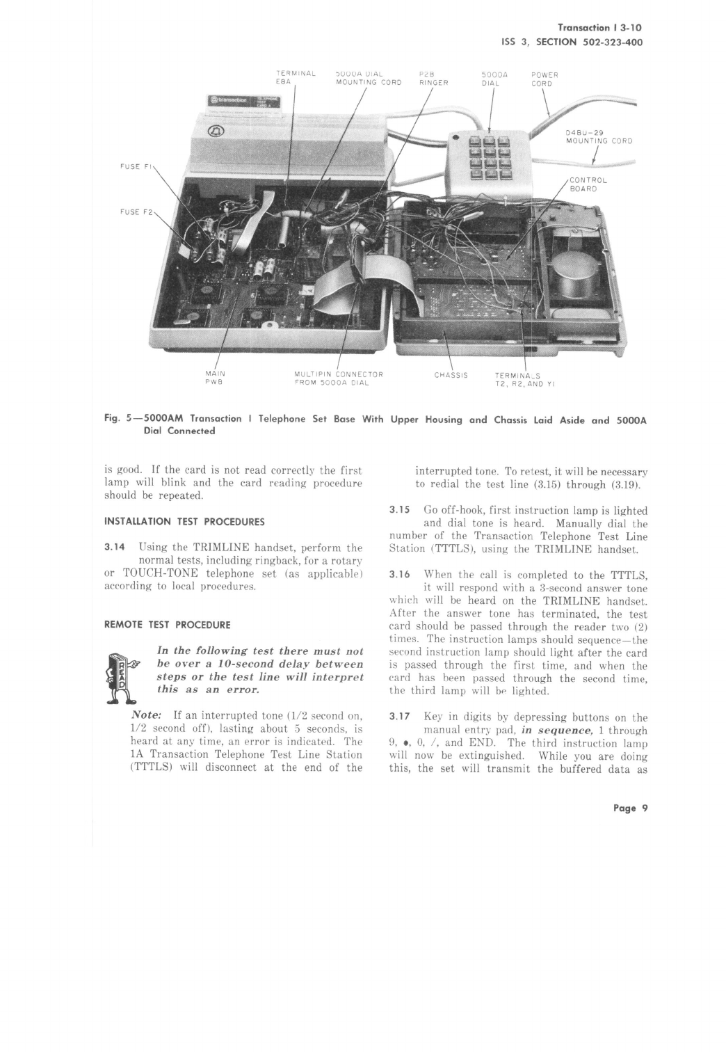
(4) Open the set (3.07); lay the upper housing
and chassis to the right (Fig. 5).
(5) Hold the lower housing up on its side and
feed the mounting cord of the dial through
the cord entrance hole in the base pan. Using
Fig. 5, make connections as follows:
(a) Plug multipin connector of mounting cord
into connector on flex :ribbon cable.
Note: Apolarizing keyin the female connector
assures proper mating of connectors.
(b) Connect 508 plug to 841935109key.
(c) Connect the black (BK) spade-tipped
mounting cord conductor to terminal E8A
on the main PWB.
Note: In early production sets there is no
terminal E8A. In this case, remove the black