Extel CB BUSPRO 2 User manual

Guide d’installation et d’utilisation
Installation and User Manual
Installatie- en gebruikersgids
Installations-und Bedienungsanleitung
Guía de instalación y de uso
Manual de instalação e utilização
Manuale d’uso e installazione
Οδηγός εγκατάστασης και χρήσης
HOTLINE
?
i
Connect 2
Connected videophone
Screen and intercom panel
REF. 720324
www.avidsen.com
v6
33
GARANTIE
ANSANS
ANS

EXTEL - CONNECT 2 - 720324
Fig. 1
1
2
1
Fig. 2
Fig. 3
5x 4 6x 4 7x 1
8x 1
1x 1 2x 1 3x 1 4x 1
1
2
1
1
2
1
3 4 765 98
1
2
123456
1
1
1
3
4
6
2
9
7
8
5
123456
1
1

EXTEL - CONNECT 2 - 720324
Fig. 4
Fig. 6
1 2 3 4 5
Fig. 5 50cm
160cm 150cm
115mm
90mm
ø6 mm
72mm

EXTEL - CONNECT - 720324
Fig. 7
1
2
1
123456
1
1
12 3456
1
Ø 2 x 0.75mm² Ø 2 x 1,5mm
2
550m 5 100m

EXTEL - CONNECT 2 - 720324 en - 1
CONTENTS
1SAFETY INSTRUCTIONS.....................................................................................p.2
2DESCRIPTION............................................................................................................p.2
3COMPONENT NAMES...........................................................................................p.2
a. Monitor
b. Intercom panel
4INSTALLATION ..........................................................................................................p.3
a. Installing the intercom panel
b. Installing the monitor
5WIRING ............................................................................................................p.3
a. Connecting the videophone
b. Connecting an electric strike plate or lock
c. Connecting a gate motor
6USER INSTRUCTIONS..................................................................................p.4
a. Videophone settings
b. General
c. Using the basic videophone functions
d. Settings
7CONNECTING YOUR EXTEL CONNECT 2 VIDEOPHONE
TO YOUR SMARTPHONE ....................................................................................p.6
a. Preparing the videophone
b. Pairing your doorkeeper with a smartphone for the first time
c. Pairing your doorkeeper with a smartphone when it is already connected
d. Interface functions
e. Settings accessible in the application
8TECHNICAL CHARACTERISTICS.................................................................. p.13
a. Monitor
b. Power supply
c. Intercom panel
9OPTIONS........................................................................................................ p.13
10 TECHNICAL SUPPORT - WARRANT ..................................................... p.14
11 SAFETY MEASURES ................................................................................. p.15
12 DECLARATION OF CONFORMITY............................................................p.16

EXTEL - CONNECT 2 - 720324
en - 2
1. SAFETY INSTRUCTIONS
Important!
•Please carefully read the user manual before installing or using this product.
• If you are installing this product for someone else, remember to leave the manual or a copy of it with the end
user.
Warning:
•The various items should only be disassembled by an authorised technician.
Safety precautions:
•To operate this system in complete safety, it is essential that the installers, users, and technicians follow all of the
safety procedures described in this manual.
•Specific warnings and warning symbols are given for items if necessary.
• The product must be set up according to the applicable standards in the country where it is installed (NF15-100 for
France).
2. DESCRIPTION (fig. 1)
1 Monitor 2 Wall bracket 3 Adapter plug 4 Intercom panel 5 Weather-proof shield
General
This videophone is composed of an interior response station with a screen and an exterior panel with an intercom and
camera, allowing the person inside to see and communicate with a visitor outside who rings the doorbell. The system
is easy to install, with only two wires needed for all functions: the doorbell, the video feed, the intercom, and the strike
plate and automated opening controls. For effective usage, please carefully read this instruction manual.
3. NOMENCLATURE
a. Monitor (fig. 2)
1. 7” (18 cm) colour screen.
2. Microphone.
3. Screen off: Viewing the camera from the intercom panel (surveillance mode).
Screen on: Navigation key (left or bottom arrow).
4. Call in progress: Answer the call. In surveillance mode: activate sound.
5. Screen off AND icon blinking: Access to images recorded during your absence.
Screen off AND icon off: Access to menu. In the menus: Confirmation key (OK).
6. Call in progress: Open electric strike plate. In the menus: Key to return to previous step.
7. Call in progress: Gate opening (dry contact). In the menus: Navigation key (right or top arrow).
8. Terminals to connect the two 15V adapter plug wires (adapter to be connected to equipment installed in compli-
ance with the applicable standards: NFC 15-100 for France).
Warning you must comply with polarity (red terminal: 15V and black ground terminal (GND))
9. Terminal for connecting the intercom panel.
b. Intercom panel (fig. 3)
1. CMOS camera lens.
2. IR LED for better visibility in the dark (light not visible to the naked eye).
3. Speaker: allows the person inside to be heard outside.
4. Light-up name holder (automatic name holder backlighting in response to light level). To change the label in the
name holder, carefully lift the plastic protector with a small screwdriver and slide out the label.
5. Microphone: allows the visitor to communicate with the person inside.
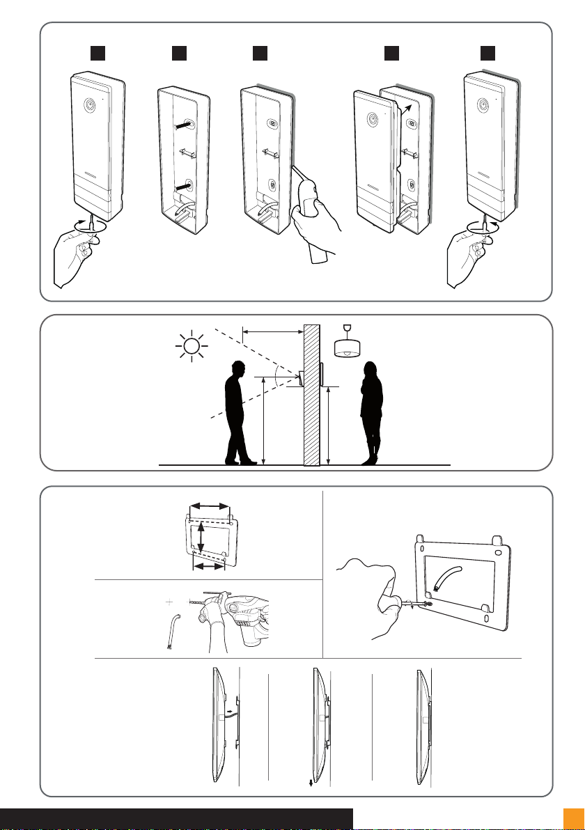
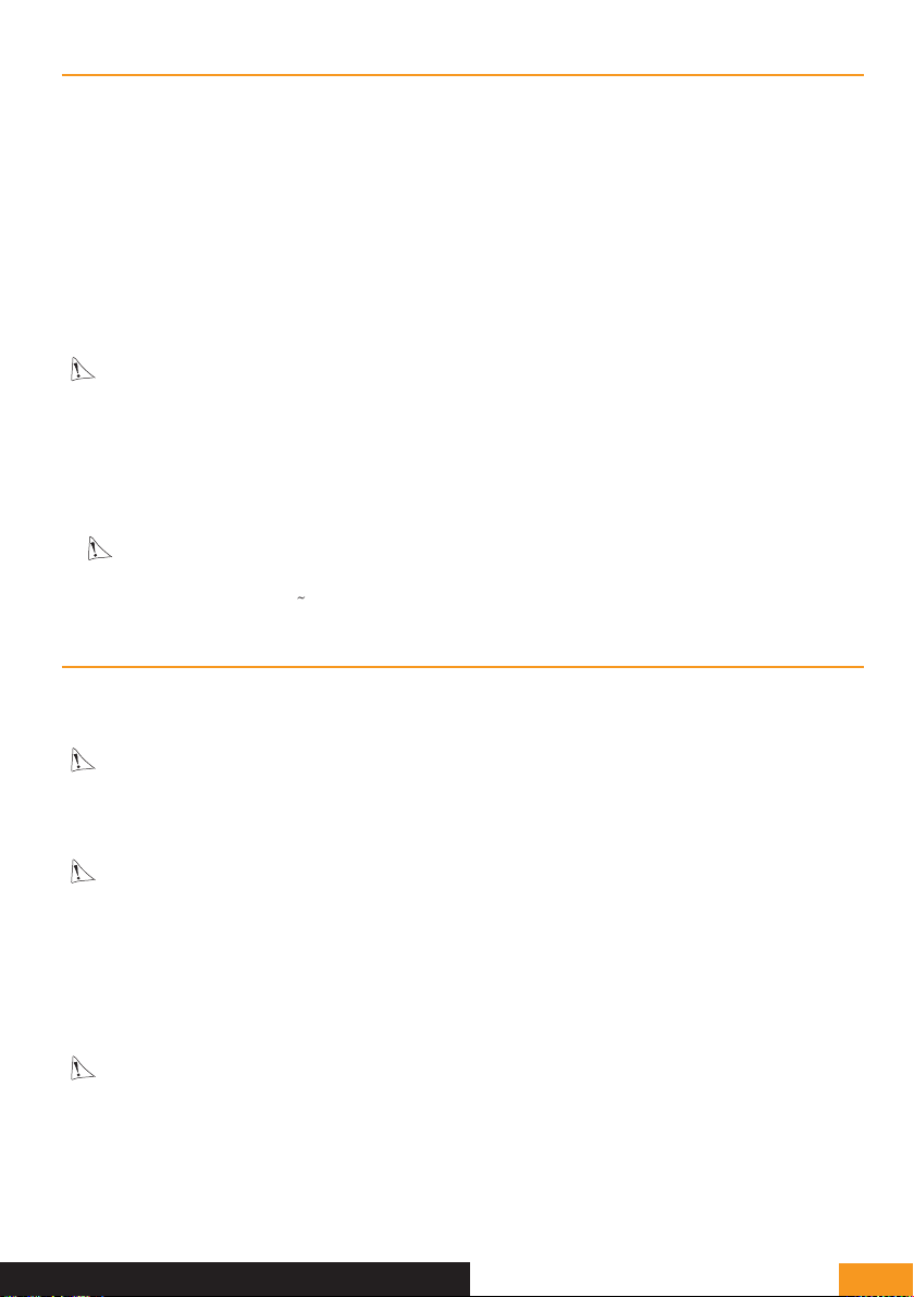
6. Screws for wall-mounting.
7. Call button: when a person presses this button, the doorbell rings inside. The screen and the camera are activated.
8. Dawn-to-dusk cell (controls the IR lighting and the name holder lighting in the dark).
9. Terminal to connect the wires from the monitor and the door openers.

EXTEL - CONNECT 2 - 720324 en - 3
4. INSTALLATION
Note: If you test your product before installing it, put the monitor on a flat surface and make sure not to test it with
the intercom panel and the monitor in the same room. If you do so, the videophone will emit a piercing sound (feed-
back effect).
a. Installing the intercom panel (fig. 4)
1. Remove the screw under the intercom panel (1)
2. Tilt the intercom panel forwards (2)
3. The lens of the panel must be placed at a height around 1.60 m (5).
4. Firmly attach the weather-proof shield with screws (2) and apply a silicon seal (3) between the shield and the
wall to prevent water from running between the two. *Do not use acetic acid-based silicone (vinegar odour).
5. After wiring, fit the intercom panel onto its weather-proof shield (4).
6. Re-install the attachment screw (5).
Important: Do not have the camera directly exposed to the sun or facing a reflective surface. At the same
time, remember to properly insert the intercom panel lug in the hole on the weather-proof shield.
Tip: it is recommended that the wires be passed through a sheath to protect them from impacts and weather.
b. Installing the monitor (fig. 5 and 6)
1. Attach the wall bracket so that the screen of the monitor will be around 1.60 m high.
2. Connect the wires coming from the intercom panel.
3. Insert the adapter wires in the back of the monitor (without plugging it into the wall socket).
Warning you must comply with the polarity (red and black terminals).
4. Install the monitor (1) on the wall bracket.
5. Plug the adapter into the 230 V wall socket.
5. WIRING
In order to avoid the risks of interference and malfunction, do not pass the wire for your videophone through the
same sheath as the electrical wires.
Warning: do not under any circumstances double wires to increase the wire size.
If there is a short circuit on the line, protection is triggered. Disconnect and reconnect the power supply after 10 s.
a. Connecting the videophone (fig. 7)
Important:
All the maximum wire lengths shown in the table (fig. 7) must be observed at the same time.
Wires to be used: • 2 x 0.75mm² wires up to 25 m long
• Two 1.5-mm2wires from 5 to 100 m long
1. Properly connect the wires according to the wiring diagram (fig. 7).
2. To connect the intercom panel, two wires are needed for all functions: the doorbell, the video feed, the intercom,
and the opening controls (strike plate and automated opening).
Important:
• For wiring, refer to the labelling on the back of the monitor and on the back of the intercom panel.
b. Connecting an electric strike plate or lock (fig. 7)
Connect it directly to terminals 3 and 4 on the back of the intercom panel (no polarity to comply with).
Note that this function is only valid if the screen is displaying the exterior video feed.

EXTEL - CONNECT 2 - 720324
en - 4
An indicator will appear to confirm.
Important: The electric strike plate or lock that you install must be equipped with a mechanical memory as for all
EXTEL models. For wiring, refer to the label on the back of the intercom panel.
c. Connecting a gate motor (fig. 7)
Directly connect the gate motor to terminals 3 and 4 on the back of the intercom panel. The intercom panel provides
a ‘dry’-contact connection, without an electric current, to connect to the button for your automated gate.
Note that this function is only valid if the screen is displaying the exterior video feed. An indicator will appear
to confirm.
6. USER MANUAL
The Extel Connect 2 videophone has 5 touch keys for: adjusting your settings, navigating through the different
menus, answering your visitors and letting them into your home.
The key functions differ from one screen to the next. To find out the keys’ functions on a given screen, refer to the
icons at the bottom of the screen immediately above the touch keys.
Also, if you wish, a navigation/selection wheel (fig. 2 #10) enables you to navigate through the menus and make the
necessary adjustments.
b. Videophone settings
When your monitor’s display is switched off, your Extel Connect 2 monitor will display the time if you swipe the touch
sensitive keys . If you touch these keys again, the main menu will appear.
25/11/2021
16 : 18
In the main menu:
• The doorbell selection and volume settings are accessible in the sub-menu
• The date and time settings in the sub-menu
• The Wifi and connectivity settings in the sub-menu
Managing and viewing images •
Management and complete erasure of the image memory and the dry-contact closure duration
•
To adjust the luminosity, contrast and colours of the image coming from the intercom panel:
• Go into surveillance mode (when the monitor display is switched off, press the key )
• The intercom panel video feed appears on the screen.
• Long press on the mechanical navigation wheel. The settings will appear on the screen.
• You can modify them and navigate from one to the other using the wheel or the touch keys.
• To come out of settings mode, press the ‘back’ key

EXTEL - CONNECT 2 - 720324 en - 5
b. General
To find out the keys’ functions on a given screen, refer to the icons at the bottom of the screen immediately above
the touch keys.
25/11/2021
16 : 18
Main touch key functions
1 • Screen off: Viewing the camera from the intercom panel (surveillance mode).
In the menus: Navigation key (left or bottom arrow)
2 • Call in progress: Gate opening (dry contact)
In the menus: Navigation key (right or top arrow)
3 • Screen off AND icon blinking: Access to images recorded during your absence
Screen off AND icon off: - First press: Access to the date and time
- Second press: Access to the menu
In the menus: Confirmation key (OK)
4 • Call in progress: Answer the call
In surveillance mode: activate sound
5 • Call in progress: Open the electric strike plate
In the menus: Key to return to previous step
c. Using the basic videophone functions
• When someone presses the button on the intercom panel, a sound goes off inside and the monitor turns on for
about 30 seconds. Once you have identified the visitor, press the key to communicate with them.
Note: One press of the key is enough to initiate communication with the intercom panel.
• When your conversation is finished, wait for the end of the timer (about 60 seconds) or press the or key
to turn off the monitor.
• To bring back the video feed: To bring back the video feed for an extra 60 seconds, press the key.
• Control of an electric strike plate: The strike plate or lock is opened when your press the button.
• Control of an automated gate: To control an automated gate, press the key.
Note that gate opening functions are only valid if the screen is displaying the exterior video feed.
• To activate the surveillance function, press the key.
d. Settings
• General:
• Setting the clock: To access the clock settings, go to the main menu and enter the sub-menu .
The clock will be visible on the standby screen and photos created by the videophone will be named according to
the date and time taken.
• Photo:
You can view your photos from the Photo menu .
- View them by going back into the Photo menu.
- To navigate from one photo to another, use the and keys.
You can select a photo by clicking the key. You can then erase it by clicking OK.
Notifications: When a visitor rings the doorbell and alarms are activated on the application, the telephone connected
receives a notification on iOS or a call on Android. After the visitor has rung, a notification transmission time can be set

EXTEL - CONNECT 2 - 720324
en - 6
in the Wifi sub-menu, by modifying the time shown opposite the icon .
7. CONNECTING YOUR EXTEL CONNECT 2 VIDEOPHONE TO YOUR
SMARTPHONE
Warning: Extel Connect 2 is not compatible with 5Ghz WiFi. Make sure that your router is set to 2.4GHz in case
of a problem.
a. Preparing the videophone
When your doorkeeper is first connected to your Extel Connect 2 video, you need to pair it with your smartphone.
To pair it, go to the WiFi sub-menu then reset the WiFi settings:
cg05167913
UID57478850
cg05167913
avidsenisolated*2G*
25/11/2021
16 : 18
1 2 3
4
20 secs
56
25/11/2021
16 : 18
Once the reset is finished, return to the WiFi sub-menu.
cg05167913
UID57478850
25/11/2021
16 : 18
1 2 3
The monitor is now ready for pairing.

EXTEL - CONNECT 2 - 720324 en - 7
b. Pairing your doorkeeper with a smartphone for the first time
NB: screenshots are from the android version of the application. The iPhone procedure is identical.
Download the Extel Connect application from Google Play or appstore.
1
Click the ‘+’ symbol then select ‘1ère installation’ (first installation). Next, scan the
QR code on the monitor screen of your doorkeeper.
2 3 4
5
Next, indicate the network to which your
video doorkeeper will have to connect
6
Turn up the sound on your phone’s speaker and click on ‘Suivant’ (Next): your application will then
emit a series of beeps that you must play for your monitor:

EXTEL - CONNECT 2 - 720324
en - 8
7
Wait for your video doorkeeper to connect to the WiFi network.
Once your application detects your doorkeeper online, name the doorkeeper as you wish
then click ‘Enregistrer’ (Save):
To finish the procedure, open the live image from your video doorkeeper by clicking on its
thumbnail. For security reasons, you will be immediately invited to change the secret con
nection code for your video doorkeeper:
8
9 10
Enter a code composed of 6 to 32 figures, then save it by clicking the icon at the top right.
11
Your video doorkeeper is now connected and operational.

EXTEL - CONNECT 2 - 720324 en - 9
c. Pairing your doorkeeper with a smartphone when it is already connected
If your video doorkeeper is already connected to your WiFi network and internet, set-up is different. No need in this
case to reset the video doorkeeper. simply go to the WiFi sub-menu to display the doorkeeper’s QR code:
cg05167913
UID57478850
25/11/2021
16 : 18
1
2 3
In the app on the smartphone; click the ‘+’ symbol then select ‘Appareil déjà connecté’ (Device already connected):
4
Enter a name of your choice in ‘Nom appar’ (Device name). Next, enter the UID (UID on the
monitor screen) or scan it by clicking on the QR code icon on the right in the application.
Next, enter the password of 6 to 32 figures that was defined in the application during initial set-up of the video
doorkeeper.
d. Interface functions
Groups the different devices and enables you to move to monitoring mode.
Enables you to add a device
Click the image to enter monitoring mode.

EXTEL - CONNECT 2 - 720324
en - 10
Enables you to manage the camera settings: name, password, WiFi network,
Channel number and alarm.
Activate/deactivate the sound.
Take a video.
Take a photo.
Full-screen mode
Open the electric strike plate or the gate.
Press and hold to speak to the visitor.
Used to delete recordings
Groups recordings

EXTEL - CONNECT 2 - 720324 en - 11
Enables you to edit photos (delete, sort and group)
Groups saved photos.
Warning only photos launched from the application are visible.
Photos of visitors’ visits are not available from the application, only from the monitor.
e. Settings accessible in the application
Many configuration options can be accessed by clicking on the icon at the top right of the live image screen:
- Renaming your video doorkeeper
- Changing its access code
- Creating a QR code readable by the intercom panel for opening
the electric strike plate (see below)
- Setting up a secret code or a fingerprint scan on the smartphone
to unlock the strike plate or gate (useful if you are not the only user of your
smartphone)
- Sharing access to the doorkeeper with another user of the Extel Connect ap-
plication
- Changing WiFi network
- Activating/deactivating notifications for incoming calls on the smartphone
- Doorkeeper microsoftware version
- Synchronisation of the doorkeeper’s internal clock with your smartphone
- Deleting the doorkeeper from the application

EXTEL - CONNECT 2 - 720324
en - 12
The QR code creation feature allows you to generate a QR code that you can send to whomever
needs to open the electric strike plate in your absence. Click on ‘Unlock QR code’ to access this menu:
- Indicate a name to the QR code for easy identification in the future
- Check here to open the electric strike plate by presenting the QR code
- Define here how many times the QR code can be used. Activate ‘Unlimited’ for
an unlimited number.
- Define here the duration of QR code validity in days/hours/minutes. This
option is useful if for example you have a friend staying with you for a week.
Activate ‘Unlimited’ for permanent validity.
- Click OK to end
- Click here to share (email, SMS or other means)
- Click here to save the QR code in your photo gallery
- Click here to delete (revoke) the QR code if you so desire
Using the QR code: after reception by the user to whom
you sent the code, they can simply ring on the
intercom panel, then present the QR code image to
the camera to unlock access.
30cm

EXTEL - CONNECT 2 - 720324 en - 13
8. TECHNICAL CHARACTERISTICS
Wiring 2-wire
Max. distance Intercom panel/camera - screen: 100m
Dry contact Lock and gate
Doorbell melody 6 melodies
Sound level: 85dB
Screen features
Diagonal: 7" (18cm)
Resolution: 800 x 480px
Photo storage: 100 max.
Mounting: wall
Specifications
Intercom panel
Sensor: C-MOS colour 650TVL
Viewing angle: h70°/ v55°
Night vision: invisible IR LEDs
Illuminated call button: yes
Illuminated label holder: yes
Strike plate control: 12V/1.1A max.
Gate control: breaking capacity 12V/2A max.
Attachment: projecting
Settings Brightness + contrast + ring volume + colour
Finish Monitor: grey and black plastic
Intercom panel: black and grey aluminium
Electrical features 15V DC/1.5A/22.5W
Operating
temperature -20°C / +50°C
Usage Monitor: interior
intercom panel: exterior (IP44)
Specifications
Product alone
Monitor dimensions: 14.9cm (H) x 19.7cm (W) x 1.8cm
(D)
Intercom panel dimensions: 20.2cm (H) x 7cm (W) x
2.8cm (D)
Weight: 1.0 kg
Kit features Dimensions: 21cm (H) x 31.5cm (W) x 9.0cm (D)
Weight: 1.35 kg
Standard and certification CE, RoHS, REACH
9. OPTIONS
• - All Extel electric strike plates
• - All Extel electric locks
• - All gate operators with a dry contact control input (e.g. 2-wire control input for the connection of a key switch)
- Recess mounting of the intercom panel possible thanks to recess-mount housing, ref. 720322.
- Additional monitor ref. 720328

EXTEL - CONNECT 2 - 720324
en - 14
10. TECHNICAL SUPPORT - WARRANTY
Fa i l u re Cause Solution
• The monitor will not turn on • The monitor is not receiving
power
• Check the power connection
• Check the position of the on/off button
• Poor picture and/or sound • Environment
• Installation or disturbance
• Check that the wires used have the right gauge and
that the connection wires for the videophone are not in
the same sheath as the 230 V wires.
• We recommend that you check your product is working
properly with a short distance test (wire 2 m min. / 5 m
max.)
• Image is too bright • Camera position • Do not directly expose the camera lens to the sun or a
reflective surface.
• No sound coming from the inter-
com panel • Insects • Check that the intercom panel microphone hole is not
obstructed.
• Monitor switched off (Indicator
LED switched off)
• Incorrect connection
or short-circuit on the line
• Resolve the connection problem, switch off the power
for 10s then reconnect
• Check the position of the on/off button
• The monitor does not pair with
the ADSL Box
• Check that the box is on 2.4 GHz Wifi
and not 5 GHz
• I receive a notification, but the
telephone does not ring • In the application settings, activate ‘sound’
• No call notification
• In the application settings, check that ‘alarm’ mode is
activated.
• In the telephone’s settings, check that energy saving
mode is deactivated for the Extel Connect application.
• On iOS, check that notifications are active for the Extel
Connect application.
• Blue screen on the smartphone • Check that the video stream is not at zero
• I can't hear the visitor
on the application • Check that the sound is not off
If needed, you can reach our technicians by telephone at
0 892 701 369

EXTEL - CONNECT 2 - 720324 en - 15
WARRANTY CONDITIONS: This product is guaranteed for parts and labour in our workshops.
The warranty does not cover: consumables (batteries, etc.) and damage caused by misuse, improper use, improper
installation, external intervention, damage due to physical or electrical shocks, dropping or atmospheric phenomena.
• Do not open the device, as this will void the warranty.
• If returning the product for after-sales service, protect the screen to prevent scratches.
• Clean with a soft cloth only, no solvents. The warranty is void if parts have been dismantled. Before cleaning, discon-
nect the equipment or switch it off at the mains.
Warning: Do not use any carboxylic acid, alcohol, or similar chemicals on the product. In addition to damaging
your device, the fumes are also hazardous to your health and are explosive.
Do not use any tool that can conduct voltage (wire brush, sharp tool, etc.) for cleaning.
The receipt or invoice is proof of purchase date.
11. SAFETY MEASURES
Damage caused by failing to adhere to the manual nullifies the warranty. We will not accept liability for damage
resulting from non-compliance!
We will not accept liability for any harm to goods or people caused by improper handling or failure to adhere to safety
instructions.
This product was manufactured in total compliance with safety guidelines. In order to maintain this status and provide
for the best possible conditions of usage, the user must adhere to the safety instructions and warnings in this manual.
: This symbol indicates a risk of electrical shock or short-circuiting.
- Only use this product with electrical current in the following ranges: 100-240 volts and 50-60 hertz. Never attempt to
use this device at a different voltage.
- Ensure that all the system’s electrical connections conform to the instructions for use.
- In commercial establishments, ensure that you adhere to the electrical installation accident prevention regulations.
- In schools, training facilities, workshops, etc. qualified personnel must be on hand to monitor electronic equipment
operation.
- You must follow the instructions for use of any other devices connected to the system.
- Please contact an experienced person if you have any doubts regarding equipment operation or safety.
- Never plug in or unplug electrical equipment with wet hands.
- When installing this product, check that the power supply cables are not at risk of being damaged.
- Never replace damaged electrical cables yourself! In this case, remove them and call an expert.
- The electrical socket must be close to the device and must be easily accessible.
WARNING Let the user know about important instructions for usage and maintenance (including
repair) in the documents accompanying the device.
Let the user know about ‘dangerous voltage’ without insulation inside the casing of the product.
The voltage is strong enough to pose a risk of electrocution.

EXTEL - CONNECT 2 - 720324
en - 16
FR - Ne jetez pas les piles et
les appareils hors d’usage avec
les ordures ménagères. Les
substances dangereuses qu’ils
sont susceptibles de contenir
peuvent nuire à la santé et
à l’environnement. Faites reprendre ces
appareils par votre distributeur ou utilisez les
moyens de collecte sélective mise à votre
disposition par votre commune.
IT - Non gettare le pile e le apparecchiature fu-
ori uso insieme ai riuti domestici. Le sostanze
dannose contenute in esse possono nuocere
alla salute dell’ambiente. Restituire questo
materiale al distributore o utilizzare la raccolta
differenziata organizzata dal comune.
ES - No tire las pilas ni los aparatos inservibles
con los residuos domésticos, ya que las
sustancias peligrosas que puedan contener
pueden perjudicar la salud y al medio
ambiente.
Pídale a su distribuidor que los recupere o uti-
lice los medios de recogida selectiva puestos
a su disposición por el ayuntamiento.
PT - Não junte as pilhas nem os aparelhos
que já não se usam com o lixo caseiro. As
substâncias perigosas que ambos podem
conter podem ser prejudiciais para a saúde e
para o ambiente. Entregue esses aparelhos
ao seu lixeiro ou recorra aos meios de recolha
selectiva ao seu dispor.
NL- Gebruikte batterijen en apparaten mogen
niet met huishoudelijk afval weggegooid
worden. De gevaarlijke stoffen die ze mogelijk
kunnen bevatten, kunnen de gezondheid en
het milieu schaden. Vraag uw distributeur
om deze apparaten terug te nemen of maak
gebruik van de middelen voor selectieve inza-
meling die door uw gemeente ter beschikking
worden gesteld.
EN - Don’t throw batteries or out of order
products with the household waste (garbage).
The dangerous substances that they are
likely to include may harm health or the
environment. Make your retailer take back
these products or use the selective collect of
garbage proposed by your city.
DE - Verbrauchte Batterien und nicht mehr
benützte Geräte sind Sondermüll. Sie
enthalten möglicherweise gesundheits- und
umweltschädliche Substanzen.
Geben Sie alte Geräte zur fachgerechten Ents-
orgung beim Gerätehändler ab bzw. benutzen
Sie die örtlichen Recyclinghöfe.
EL - Μην πετάτε τις μπαταρίες και τις
συσκευές τέλους κύκλου ζωής μαζί με
τα οικιακά απορρίμματα. Οι επικίνδυνες
ουσίες που μπορεί να περιέχουν μπορεί να
βλάψουν την υγεία σας και το περιβάλλον.
Ζητήστε από τον διανομέα σας να πάρει
πίσω αυτές τις συσκευές ή χρησιμοποιήστε
τα μέσα επιλεκτικής συλλογής που παρέχει
ο δήμος σας.
FR - Ce symbole indique que l’appareil s’installe et s’utilise uniquement à l’intérieur
IT - Questo simbolo indica che l’apparecchio si installa e si utilizza unicamente all’interno
ES - Este símbolo indica que el aparato se instala y utiliza únicamente en el interior
PT - Este símbolo indica que o aparelho só pode ser instalado e usado em interiores
EN - This symbol indicates that the device must only be installed and used indoors
NL - Dit symbool betekent dat het apparaat alleen binnen mag worden geïnstalleerd en gebruikt
DE - Dieses Symbol zeigt an, dass das Gerät nur innen installiert und verwendet wird
EL - Αυτό το σύμβολο υποδεικνύει ότι η συσκευή πρέπει να εγκατασταθεί και να χρησιμοποιηθεί μόνο σε εσωτερικούς χώρους.
12. DECLARATION OF CONFORMITY
Avidsen, undersigned, states that radio equipment such as the Extel Connect 2 is compliant with directive 2014/53/EU
Standards:
Directive 2014/35/UE:
• EN 50665 :2017
• EN 62368-1 :2020+A11 :2020
Directive 2014/30/UE:
• EN 301 489-1 V2.2.3 (2019-11)
• EN 301 489-17 V3.2.4 (2020-09)
• EN 55032 :2015+A11 :2020
• EN 55035 :2017+A11 :2020
Directive 2014/53/UE:
• EN 300328 V2.2.2 (2019-07)
À Tours, 06/05/2022
Alexandre Chaverot, CEO
Pour en savoir plus :
www.quefairedemesdechets.fr
Other manuals for CB BUSPRO 2
1
This manual suits for next models
1
Table of contents
Other Extel Telephone manuals

Extel
Extel MOMBO User manual

Extel
Extel Karo HD-2660 User manual

Extel
Extel WEVP 630 E BIS User manual

Extel
Extel WAVE 2 User manual

Extel
Extel WEVA DB-9035E User manual

Extel
Extel WEVPSF 659 User manual

Extel
Extel WEVP 252 BIS User manual

Extel
Extel VisioSmart 720303 User manual

Extel
Extel WEVP 256 User manual

Extel
Extel Compact User manual