(b) Modify the telephone
set
wmng
and
terminate the spade-tipped key leads
as shown in the appropriate modificatton
table (Fig.
18).
(c)
Refer to Section
518-450-100
for necessary
KTU
and KSU connection information
with the DND feature.
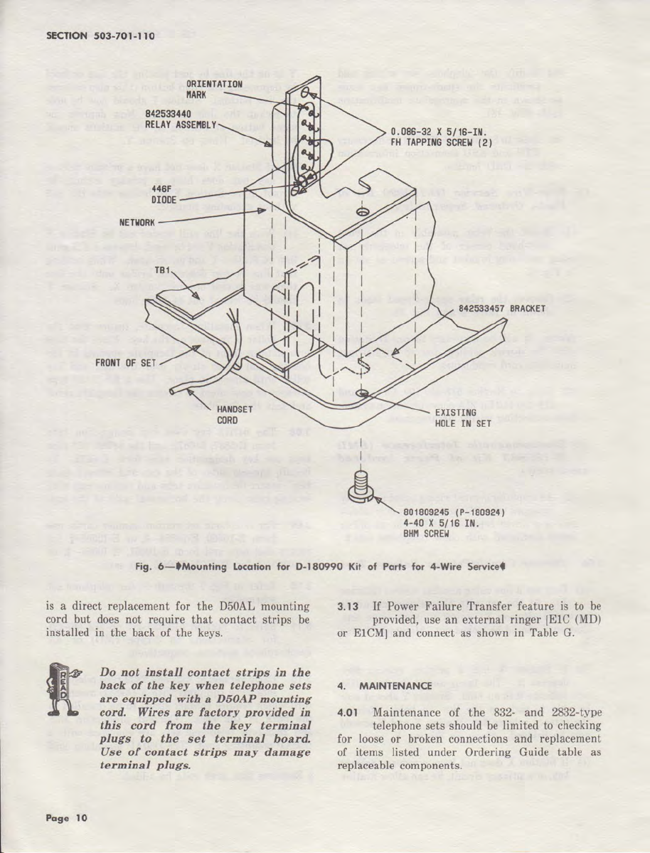
(I) Four-
Wire
Service
(D-180990
Kit
of
Parts,
Ordered
Separately):
(1)
Mount the relay assembly
in
the
front
right-hand corner of the telephone
set
using mounting bracket and screws as shown
in
Fig.
6.
(2)
Connect the relay spade-tipped leads as
shown
in
Table L and Fig.
19.
Note:
It
will
be
necessary to run D-Station
wire for 4-wire service due to insufficient
mounting cord conductors.
(3)
Refer to Section 518-450-100 for
7A
and
518-450-110 for
21A
communication system
interconnecting wiring arrangement.
(m)
Electromagnetic
Interference
(EMI)
D-180883
Kit
of
Parts
(ordered
separately).
(1)
An
amplifier printed wiring board assembly,
equipped with RFI suppression is available
and is a direct replacement for the amplifier
board furnished with these telephone sets
.•
3.06
Privacy
Circuit/Privacy
Release
Test.
(a) Busy out a line using another station (Station
X).
At the
set
with the privacy circuit to
be
tested (Station
Y),
go
off-hook
on
same line.
Station Y should
be
locked out.
Hang
up
Station
Y.
(b)
If
Station X has a privacy release key,
depress it. The lamp under the busy line
will indicate
it
is on-hold. Station Y should now
be
able to pick up
the
line on hold. Release
the privacy release key, Station X and Y should
now
be
bridged.
Hang
up Station
Y.
(c)
If
Station X does not have a privacy release
key, or a privacy circuit, he can allow Station
ISS
5,
SECTION
503-701-110
Y in on the line
by
just
placing the line on-hold
by
depressing the Hold button (this also releases
the
line button). Station Y should
now
be
able
to pickup the line on hold. Now depress the
same button
at
Station
X,
the stations should
be bridged.
Hang
up Station
Y.
(d)
If
Station X does not have a privacy release
key but does have a privacy circuit, he
cannot allow Station Y to bridge onto the call
without excluding himself.
(e) With the line still busied out
by
Station X
and Station Y not bridged, depress a different
line
on
Station Y and
go
off-hook. While holding
that
line button depressed bridge onto the line
that
was busied out
by
Station
X.
Station Y
should
be
locked
out
of both lines.
3.07 When installing faceplate, insure
that
the
collar is
in
place on the key. Place the tabs
into slots in front of the faceplate opening
in
the
housing and lower slowly over
the
dial and key
collar until almost in place. Use a KS-21107 type
releaser or equivalent to release
the
faceplate catch
and
seat
the faceplate.
3.08
The
647G5
key uses key designation
tabs
form E-5837, E-6672, and the
647S5,
651-type
keys use key designation tabs form E-6672.
To
install, squeeze sides of the cap and remove from
key.
Insert
designation tabs and replace cap with
locking tabs along the horizontal axis of the key.
3.09 For telephone
set
station number cards, use
form E-10360, E-10364-
§,
or E-10368-§, for
rotary dial sets and form E-10361, E-10365-
§,
or
E-10369- § for TOUCH-TONE dial sets.
3.I 0 Refer to Fig. 7 through
16
for telephone
set
schematics.
3.11 Refer to Section 512-620-487 or
512-740-471
for connections to
3-type
(MD)
or
4A
speakerphone systems, respectively.
3.12 Early version of
832-
and 2832-type telephone
sets were equipped with a D50AL mounting
cord which require contact
strips
to
be
installed
in
the back of the keys.
Current
production
832-
and 2832-type telephone sets
are
equipped with a
D50AP mounting cord. The D50AP mounting cord
§ Requires
that
area code
be
added.
Page 9