Bell F-58555 Guide

BELL SYSTEM PRACTICES
Plant Series
TELEPHONE SETS—F-58555
IDENTIFICATION, INSTALLATION, CONNECTIONSr
1. GENERAL
SECTION 502-690-101
Issue 1, October 1970
AT&TCo Standard
AND MAINTENANCE
D50K MTG CORD
REJECT BAR
1
1.01 The F-,M55fi telephone set (Fig. 1and 2) is
adesk-type, &button key card dialer, providing
for :iutomatic. and manual calling,
Fig. 2—F-58555 Telephone Setr Interior View
2. IDENTIFICATION
Ordering Guide
Fig. l—F-58555 Telephone Set
1.02 It is equipped with aF-,58.553 dial which
contains amanual KC 12-button TOUCH-TONE n
dial, ~x~larity guard, and reed switch card reader,
1.03 This set is similar to the ‘2662.A1 telephone
set and may be used to fill the demand for
:i car(] dialer that will provide extended life in high
usagd a~)plications,
2.01
2.02
Basic Telephone Set:
Set, Telephone, F-.58555-*
Replaceable Common Components:
.Card, Set, 840360564 (20 cards)
gCord, Mounting, D50K-*
●Dial, F-58553
●Faceplate (see Table A)
gKey, 599.4 or 657A
.P-13E363 Card Index Set (9 cards)
●P-24E474 Retainer Card
c.Amcr]can Telephr)ne and Telegraph Company, 197(J
Printed mL’.S..L Page 1

SECTION 502-690-101
●P-44E129 Designation Strip ●ealed reed contacts
.P-82BO* Housing Assembly ●Reject button, releases card without dialing,
releases call bar for manual dialing when
card is stuck
●Ringer, MIA
●Set, Hand, G3A4*t ●Polarity guard for end-to-end signaling
*Add appropriate color suffix, see Table A. ●Expanded line switch for use with 3-type
speakerphone
“~Same as G3AR handset, 4indicates length
of handset cord. ●Key telephone system use 1A, lA1, or 1A2
●AC buzzer (optional)
TABLE AApplication
COLOR ORDERING GUIDE 2.05 This set can be used on CO, PBX line circuits,
and 1A, lA1, or 1A2 key telephone systems.
ICOLOR ISUFFIX ICOORDINATED IFACEPWTE
COLOR PIECE PART I
IBlack ]-03 ICharcoal \840171706 I
3. INSTALLATION AND CONNECTIONS
IIvory I-50 jMuted Ivory ]840171805 I
IGreen ]-51 ILt. GreerI I840171714 ]3.01 Install the F-58555 telephone sets in accordance
with standard practices for desk-type, 6-button
key telephone sets. Refer to appropriate connection
figures and tables for connections and wiring options.
Red -53 Muted Red 840171691
Yellow -56 Lt Yellow 840171722
White -58 Lt Gray 840171730
Rose Pink -59 Muted Pink 840171’748 3.o2 One sheet of perforated blank designation
strips (P-44 E129) is supplied with each set.
Remove faceplate (4.04) and install strip at key
location.
Lt Beige -60 Muted Beige 840171755
Lt Gray -61 Charcoal 840171706 ‘
\Aqua Blue -62 Muted Blue 840171763
Turquoise -64 Muted Turq 840171771 Optional Features
IIII13.03 Buzzer: AKS-20419L1 (10 volt AC only)
buzzer (ordered separately) may be used in
this set as an auxiliary signal. This is an insulated
buzzer and may be mounted in any convenient
location with asingle screw. Space limitations do
not permit use of aKS-8109 type buzzer.
2.03 Optional Apparatus or EQw”pment (odered
separately):
●Buzzer, KS-20419L1
3.04 Speakerphone: When speakerphone is
required, make the necessary lead connections
in accordance with Table B. Refer to appropriate
connection figure for mounting cord lead connections
to 66-type connecting block.
Design Features
2.04 Features of this set are:
●Slot for smaller size cards with rectangular
holes 3.o5 Signaling: To convert pickup keys from
(locking) to (nonlocking) remove the P-1OE837
screw from the key plunger at the key being
converted, and refer to Table Cfor key lead
connections.
.Manual 12-button TOUCH-TONE dial
●Roller card feelers
Page 2

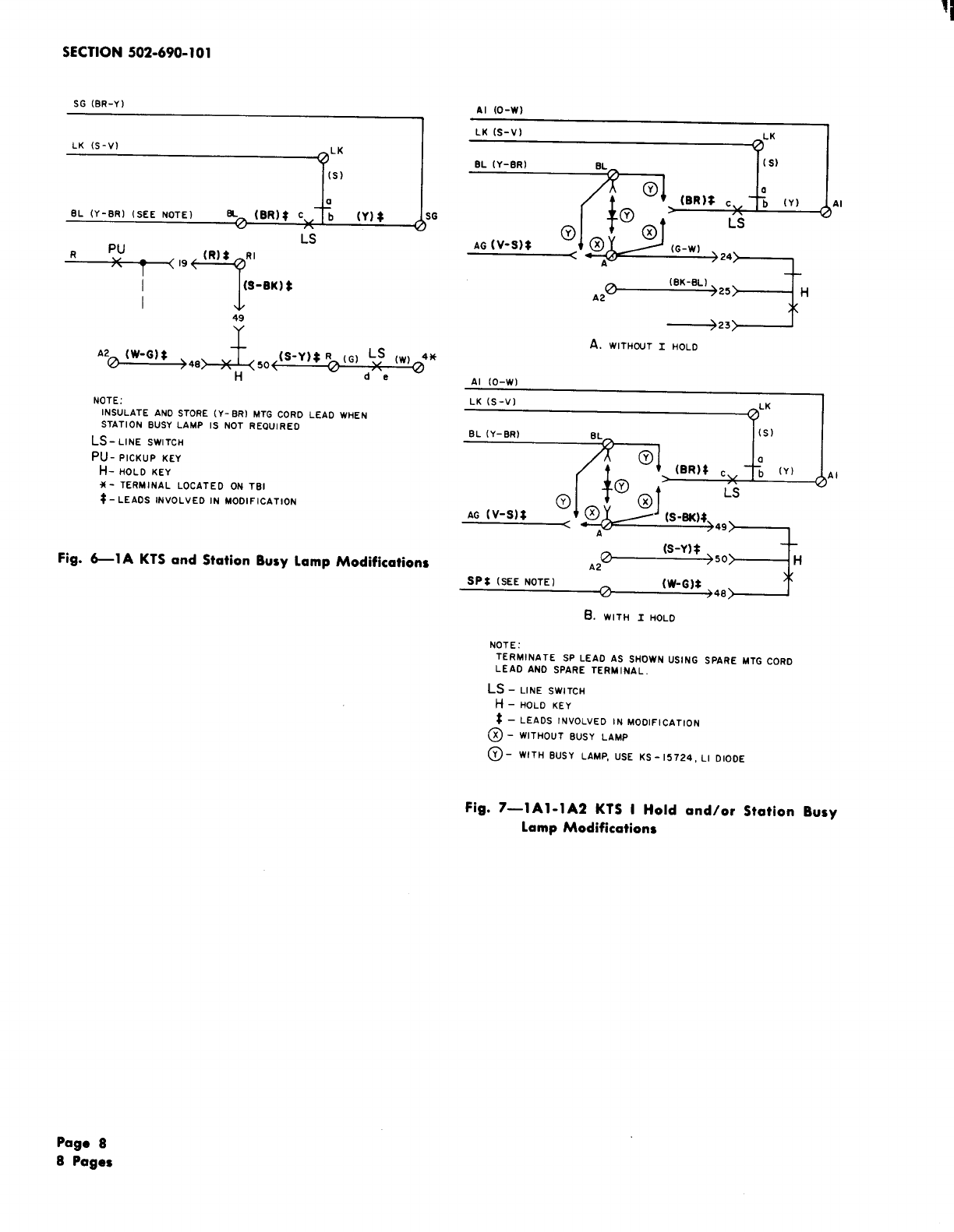
3.06 Station Busy Lamp: Connections for this
feature are shown in Fig. 6for 1A KTS
and Fig. 7for lA1 or 1A2 KTS.
3.07 IHold: This feature can be provided for
lA1 and 1A2 KTS only, Fig. 7provides the
necessary connections.
Card Size
3.08 The card slot of the F-58553 dial will accept
only the smaller size cards with rectangular
holes (2-1/8 by 3-3/8 inch). These cards are slightly
smaller in size than the cards used with 2662-type
card dialers. Either the punchable card supplied
with the set or prepunched cards (KS-20640) furnished
by the customer may be used. Cards for this new
dialer are not interchangeable with cards used with
earlier model card dialers.
1SS 1, SECTION 502-690-101
(6) If astop is punched after the last telephone
number digit, the Rbar must be operated
to release the card.
.— —.
Is
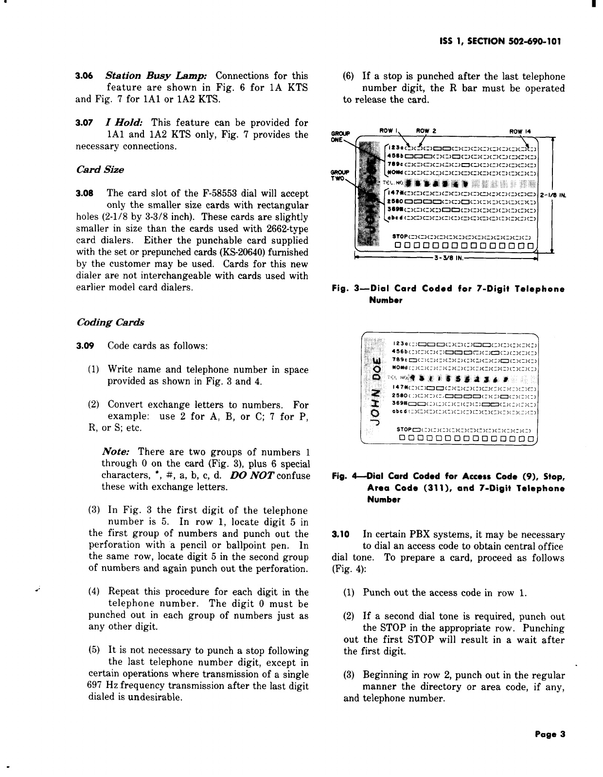
Fig. 3—Dial Card Coded for 7-Digit Telephone
Number
Coding Cara%
3.09
(1)
(2)
Code cards as follows:
Write name and telephone number in space
provided as shown in Fig. 3and 4.
Convert exchange letters to numbers. For
example: use ~for A, B, or C; 7for P,
R, or S; etc.
Note: There are two groups of numbers 1
through Oon the card (Fig. 3), plus 6special
characters, *, #, a, b, c, d. DO NOT confuse
these with exchange letters.
(3) In Fig. 3the first digit of the telephone
number is 5. In row 1, locate digit 5in
the first group of numbers and punch out the
perforation with apencil or ballpoint pen. In
the same row, locate digit 5in the second group
of numbers and again punch out the perforation.
/(4) Repeat this procedure for each digit in the
telephone number. The digit Omust be
punched out in each group of numbers just as
any other digit.
(5) It is not necessary to punch astop following
the last telephone number digit, except in
certain operations where transmission of asingle
697 Hz frequency transmission after the last digit
dialed is undesirable.
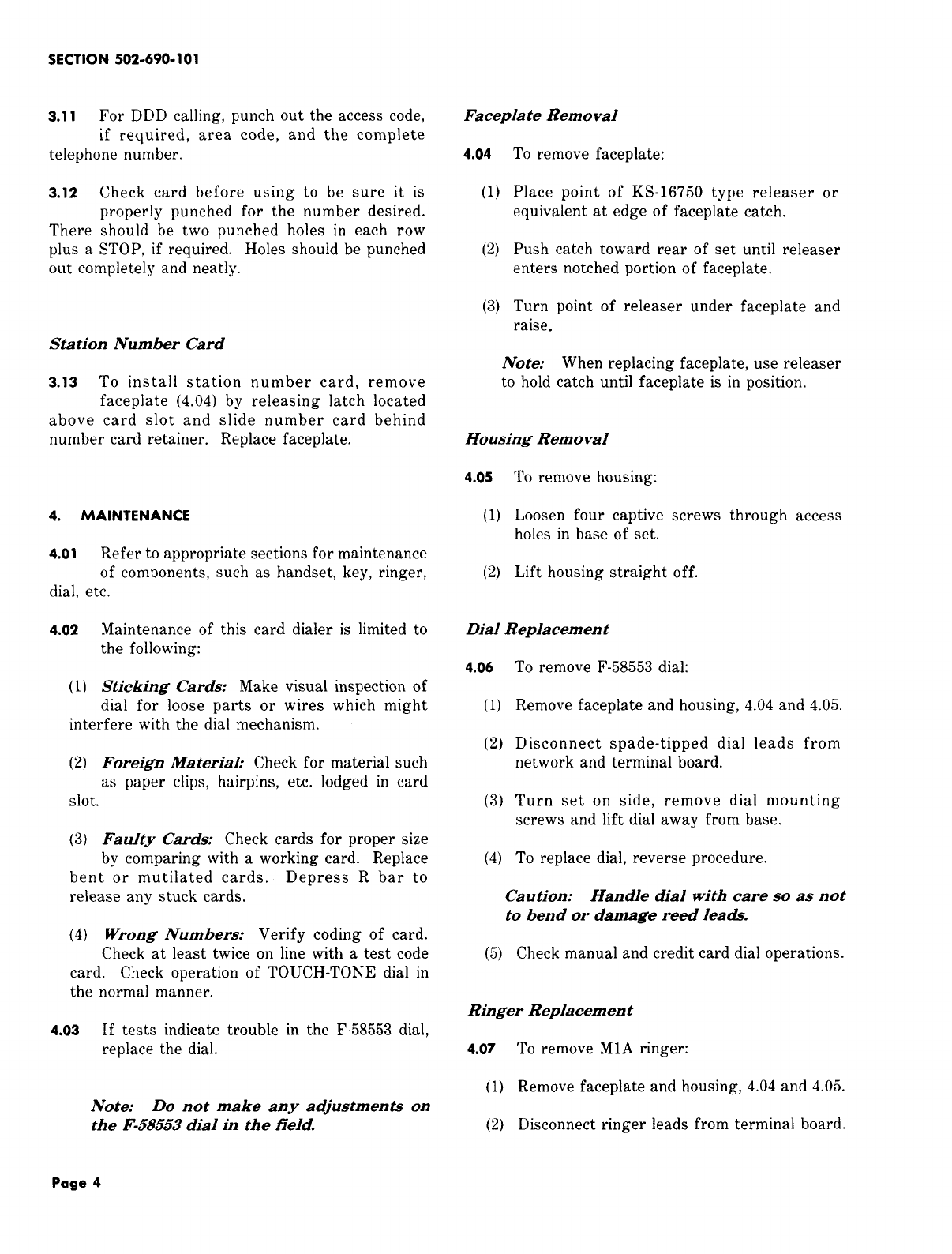
stop,Fig. 4-Dial Card Coded for Access Code (9),
Area Code (31 1), and 7-Digit Telephone
Number
3.10 In certain PBX systems, it may be necessary
to dial an access code to obtain central office
dial tone. To prepare acard, proceed as follows
(Fig. 4):
(1) Punch out the access code in row 1.
(2) If asecond dial tone is required, punch out
the STOP in the appropriate row. Punching
out the first STOP will result in await after
the first digit.
(3) Beginning in row 2, punch out in the regular
manner the directory
and telephone number. or area code, if any,
Page 3

SECTION 502-690-101
3.11 For DDD calling, punch out the access code,
if required, area code, and the complete
telephone number.
3.12 Check card before using to be sure it is
properly punched for the number desired.
There should be two punched holes in each row
plus aSTOP, if required. Holes should be punched
out completely and neatly.
Faceplate Removal
4.o4 To remove faceplate:
(1) Place point of KS-16750 type releaser or
equivalent at edge of faceplate catch.
(2) Push catch toward rear of set until releaser
enters notched portion of faceplate.
(3) Turn point of releaser under faceplate and
raise.
Station Number Card
3.13 To install station number card, remove
faceplate (4.04) by releasing latch located
above card slot and slide number card behind
number card retainer. Replace faceplate.
4. MAINTENANCE
4.01 Refer to appropriate sections for maintenance
of components, such as handset, key, ringer,
dial. etc.
4.02 Maintenance of this card dialer is limited to
the following:
(1) Sticking Cards: Make visual inspection of
dial for loose parts or wires which might
interfere with the dial mechanism.
(2) Foreign Material: Check for material such
as paper clips, hairpins, etc. lodged in card
slot.
(3) Faulty Cards: Check cards for proper size
by comparing with aworking card. Replace
bent or mutilated cards. Depress Rbar to
release any stuck cards.
(4) Wrong Numbers: Verify coding of card.
Check at least twice on line with atest code
card. Check operation of TOUCH-TONE dial in
the normal manner.
4.o3 If tests indicate trouble in the F-58553 dial,
replace the dial.
Note: Do not make any adjustments on
the F-58553 dial in the field.
Note: When replacing faceplate, use releaser
to hold catch until faceplate is in position.
Housing Removal
4.o5 To remove housing:
(1) Loosen four captive screws through access
holes in base of set.
(2) Lift housing straight off.
Dial Replacement
4.06 To remove F-58553 dial:
(1) Remove faceplate and housing, 4.04 and 4.05.
(2) Disconnect spade-tipped dial leads from
network and terminal board.
(3) Turn set on side, remove dial mounting
screws and lift dial away from base.
(4) To replace dial, reverse procedure.
Caution: Handle dial with care so as not
to bend or damage reed leads.
(5) Check manual and credit card dial operations.
Ringer Replacement
4.07 To remove MIA ringer:
(1) Remove faceplate and housing, 4.04 and 4.05.
(2) Disconnect ringer leads from terminal board.
Page 4

1SS 1, SECTION 5O2-69O-1O1
(3) Remove dial mounting screws and lay dial TABLE B
aside to gain access to ringer. Do not
disconnect dial leads. SPEAKERPHONE CONNECTIONS
(4) Remove screws holding ringer to base and WIRE OR LEAD REMOVE FROM CONNECT TO
remove ringer, STORED LOCATION
(5) To replace ringer, reverse procedure used T1 V-G ●TB2-9
to remove ringer. RI G-V ●,TB2-R
Mtg IR BR-V
Cord ●TB1-4
AG V-S bTB2-A
LK S-V ●TB2-LK
o●TB2-T
Dial v●TB2-9
TABLE C
PICKUP-SIGNAL KEY CONVERSION
CONVERSION 599A KSV LEADS
OPTIONS (0.w) (s-w) (G-R) (BL-BK) (BR-BK) (BR-W)
HPPPPP (Note) A2 A2 A2 A2 A2 5
HPPPPS A2 A2 A2 A2 SG 5
HPPPSS A2 A2 A2 SG SG 5
HPPSSS A2 A2 SG SG SG 5
HPPPP*S” A2 A2 A2 S1 A+ S1
HPPP*P*s* A2 A2 S1 S1
HPP*P*P*s* A+ S1
A2 S1 S1 S1 A+ S1
*These arrangements use line switch controlled ground for common signal key used with private or intercommun-
icating lines. Common signal key should be used to operate asignal relay.
fFor 1A KTS connect (BR-BK) key lead to BL terminal.
Note: To convert from pickup (locking) to signal (nonlocking) remove the P-1OE837 screw from the plunger at the
key position being converted.
Page 5

SECTION 502-690-101
IA I-IA2
KTS LINE
CONNECTIONS
rmr
=1=
R(1) 2
R(2) 8
R(3) 14
R(4) 20
R(5) 26
T(l) II
T(2) <
7
T(3) <
!3
T(4) <
19
T(5) <
25 <
SPARE 31
<<
SPEAKERPHONE “50 <
[ ; ;~
AI Cx?B 4
A,H, SOR S1 3
IA I-IA2 A,14, SOR S1 9
KTS LINE A,H, SOR S1 15
CONNECT 10NS A,H, SOR S1 21
A,H, SOR SI 27
SIGNAL sG 38
GROUNO B’ OR LS 37
BUSY LAMP
[~;=;
ROR RI 40
RINGZR
CIRCUIT BOR BI 39
‘L(l) 6
IA I-IA2
KTS LAMP
CONNECT 10NS a
‘G(4) 23 ‘
L(5) 30
‘G(5) 29
HL 36
HLG 35
.810 ‘
[~~;
B16
22
1A KTS B
828
e34
SPARE 33
P/O D50K MTG CORO 599A OR
(BL-w) 657A KEY
J(BL-w) *Pu
I<
4<(6R-w) 3
7<(O-R) 5
(S-R)
10< 7
(G-BK )
13< 9
;’=< 19 (R)
(BL-Y)
16t T11>
(EL-Y) *
(w-8L) *
26 f(w-B’) >26~44~ (G)
29< (w-.9R) 28
32< (R-O)
(R-S) 30
35{ 32
38< (OK-G) 34
(y-L3L) /%
41< T36 ~
L@kL* [s)
(s-v )
25< *
<(o-w) Al
nA(G-w)
2(w-o) WI(O-R) A(o-w) w(BK-BL)
27{ (w-s) w)27~2
2(R-O)
30(
w
w
u
=
(s-w)
(R-G) W3(S-R) >29~4
33< >31~6 (G-R )A2
36( (BK-BL) 4(w-BR )~33~8 (EL-EM)
(BK-OR) ~5(BR-W)
39< 335~ 10 (.9R-BK)
19< (BR-y) aSG +12 (o-Y)
44 ((Y-BR) 42 EL MIA RINGER (NOTE 3)
(s-y) :--
al <—@
45 ((Y-s) * *
3
?8
6
31
3
34
1< (w-G ).-
Y38
((BL-R ).. .
>14
((R-13L)
{(BR-R )>39
>15
<(R-i9R) )40
(0-BK ).-
12< >16
37< (BK-0) >41
15( (S-BK )b17
(BK-S ),.,
$0(
(G-Y) 8(G-Y) >42
18< >18
13< (Y-G) 7(Y-G)
(s-w) w>43
)((G-R )*
)<*
(BL-BK )
(t3R-BK )
4< *
17( (o-Y) *
(Y-o) 6[R-S)
Lz ()37
>
>
>
>
>
>
)
>
>
>
>
>.
Fig. 5—F-58555 Telephone Set Connections (Sheet 1of 2)

1SS 1, SECTION 5O2-69O-1O1
*(0)
II Cs
PG (v)
*
P/O DIAL
R(G) ~LS
..
(R) “e (W) 4* (O-R) (0-BK) Ct
nw%
(w-s )T
(G) T(G) WAJ
u
GNt (W-BL)
-;
Cs Cs tI
(BL-BK )
(,.) ‘sw“””
~w-,’+ 23+
:(s-Y) <::
<3H
(S-BK) <49 EMB
*mP/O 050K
NTG CORO
3=
[
Bz 42 21
BUZZCR LEAOS Bz, 41 46
SPARE 44 22
SPARE 43 47
[
RI 46
TI 23
45 48
SPEAKERPHONE ,R 48 24
1’ 47
AG 49
49
(I<]50
<(BL-v )
(V-EL) ;
<(o-v )
<(v-o) *
((G-v) *
<(V-G) *
~*
<(BR-V) *
((V-BR) *
<(v-s) *
NOTES:
1.
2.
3.
66E-TYPE CONNECTING BLOCK 5HOWN. MOUNTING
CORO MAY Bf PLUGGEO OIRECTLY INTO CONNECTOR
CABLE. COLORS ANO PIN NUMBERS FOR CONNECTOR
CABLE ARE SAME AS MOUNTING CORO.
AUXILIARY BUZZER MAY Bf INSTALLED. USC SPARE
LEAOS ANO TERMINALS TO CONNCCT TO ECU IPMENT.
FOR BRIOGEO RINGING ON IST LINC, CONNECT (R)
RINGER LEAO TO (BL-w) AND (BK) RINGER LEAO
TO (W-BL) INSULATEO AND STOREO LEAOS.
CONNECT (S) RINGER LEAO TO KANO (S-R)
RINGER LEAD TO AOF NETwORK.
LIt
7
(s-BK )
(S-21K)
ROTARY CR
EXCITATION —
‘WITCH (S-R) 1
e
(S-R)
L2t (V-BL)
CR
1
P/O F-58553
RCOIAL CIRCUIT
1 1 r
BB
L4 (w-s) -$; (Y-S) H4
((H●::
L3 (W-O) L3 H3 (Y-O) H3
(~II+)
L2 (w-G) L2 H3
(+I()+( )
LI {(w-BR )HI (Y-SIR) HI
I+I*)
LC (BR) CR (BRJ HC (S) CR
A-(s)
.
4. LINE SWITCH OFF-HOOK
SEWENCE :
bc CLOSES
de ANO b’c’ CLOSE
ob ANO o’ti OPEN
fg OPENS
LEGENO
A-MANUAL OIAL CONTACTS
B- CARD REAOER OIAL CONTACTS
CR- CARO REAOER SWITCH
PIJ -PICKUP KEY
H- HOLO KEY
PG -POI-A’ITY GUARO
*- INSULATEO ANO STOREO
t- 4010D NETWRK TERMINALS
+- SCREW TERMINALS LOCATEO ON
TBI, UNMARKEO SCRCW TERMINALS
LOCATEO ON TB2.
CS_ COMMON SWITCH (DIAL)
LS- LINE SWITCH
Fig. 5-F-58555 Telephone Set Connections (Sheet 2of 2)
Page 7

SECTION 502-690-101
sG(BR-Y]
LK (S-V)
~“ [s)
+0
EL (Y-BR) (SEE NOTE) ~- (BR)t Ch(Y) *
RPu ,9 (R): RI
\
“7
(S-BK) ~
49
Y
LS
AZ (W-G): 48
H&, so (S-Y)$R~tG) L$ [w, 4*
Hwde
NOTE:
INSULATE AND STORE (Y-BRI MTG CORO LEAO WHEN
STATION BUSY LAMP IS NOT REQUIRED
LS-LINE SWITCH
PU- PICKUP KEY
H-HOLD KEY
X- TERMINAL LOCATED ON TBI
$- LEAOS INVOLVEO IN MODIFICATION
Fig. 6-1 AKTS and Station Busy Lamp Modifications
Al (O-W)
“(S-V)
~LK I
(BK-BL)
A2° 25
‘5
H
~23
A. WITHOUT IHOLO
Al [O-W)
‘K [S-V)
~LK
A
Al
0(s-Y)*
,A2 J’O+H
SPS (SEE NOTE) n(W-G)* }48J
B. WITH IHOLO
NOTE:
TERMINATE SP LEAD AS SHOWN uSING SPARE MTG CORD
LEAD AND SPARE TERMINAL.
LS -LINE SWITCH
H-HOLO KEY
$- LEADS INVOLVED IN MODIFICATION
@-WITHOUT BUSY LAMP
@- wlTH BUSY LAMP, USE KS-15724, i-l D,ooE
Fig. 7—l A1-1A2 KTS IHold and/or Station Busy
Lamp Modifications
Page 8
8Pages
Table of contents
Other Bell Telephone manuals