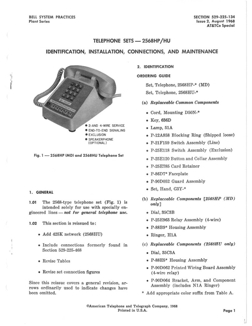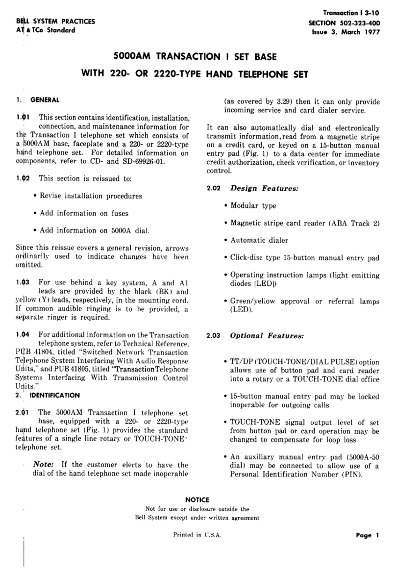
SECTION503-200-109
the telephone company retains ownership of the 3.06 Line and Ringer Connections:
transmission and signaling components. (Fig. 2
and 3). (1)For singleline and two-partyservice,refer
to TableB.
Ordering Guide (Refer to Table A) (2) For adjustments and ringer cutoff feature
2.02 BasicTelephone Set Ordering Information: of theP1Aringer,refer to Section 501-259-101.
Example: Set,Telephone,881A105t is a 4. REMOVAL OF TELEPHONECOMPANY-OWNED
black set equipped with a rotary dial (Fig. 1). COMPONENTS
tRefer to Table A for available codes and 4.01 When it is desired to discontinue telephone
ordering guide, service of these DESIGN LINE telephone
sets,proceed as follows:
2.03 These telephone sets are intended to be
used as single line or two-party desk sets Note: Remove telephone company-owned
and are not recommended for use on four- and components that can be easily removed. Refer
eight-party service, to Fig. 3 for identification of company-owned
components.
(1) Remove four base mounting screws from
3. INSTALLATION AND CONNECTIONS the bottom of the telephone set and remove
bottom base (Fig. 4).
3.01 These telephone sets are furnished from
the factory fully assembled and wired for (2) Remove one dial frame and two line switch
bridged ringing. To connect the telephone set, mounting screws from the base and remove
plug the mounting cord into a 625A jack or if the dial frame and line switch (Fig. 5).
existing jack is a 548A or equivalent, use the 225A
adapter furnished with each set. (3) Remove one network, two ringer and three
dial mounting screws from the base and
3.02 The internal connections for the 881A- and remove network, ringer and dial (Fig. 6).
881B-type telephone sets, for nonkey system
use, are shown in Fig. 7 and 9. (4) Unscrew transmitter and receiver caps and
remove T1 transmitter and U3 receiver units.
3.03 Connections for 1A KTS do not require any
telephone set modifications and are wired (5) Replace dial frame and base using four screws
same as Fig. 7. removed in Step (1), see Fig. 4.
3.04 Connections for use with 1A1 or 1A2 KTS 4.02 Follow local procedures for returning telephone
are shown in Fig. 8 and 10. Table C includes company-owned components.
necessary wiring modification required for 1A1 or
1A2 key telephone system use. 4.03 When it is desired to return a set to Western
Electric for repair, it should be packed using
3.05 To gain access to the interior of these sets the D-180600 Kit of Parts which contains packing
for wiring changes, refer to Part 4. materials and instructions.
Page 2
