(
\
•
()
BELL
SYSTEM PRACTICES
AT&TCo
Standard
SECTION 512-700-lOD
Issue
2,
September 1974
4A
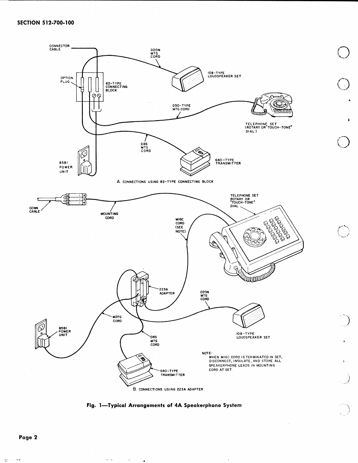
SPEAKERPHONE SYSTEM
1. IDENTIFICA
TiON
1.01 The
4A
speakerphone system
is
a hands-free
voice switched system for use as a telephone
adjunct
and
is
a
replacement
for
the
3-type
speakerphone system.
1.02 This section is reissued to add information
on:
• lOSAR loudspeaker
set
• 680AR and 680AR14
transmitters
• 82B connecting block
• Station
busy
lamp circuit
1.03 The
4A
speakerphone
system
consists
of
a
transmitter,
loudspeaker
set,
power
unit,
and either a connecting block
or
adapter
that
when
connected to a suitable telephone set, provides:
o Hands-free telephone operation
• On-hook dialing (when dial
is
not
obstructed)
• Automatic switching from speakerphone to
handset
operation
•Transmitter
muting for private conversation
• Visual indication when system is in use
•
Cutoff
common
ringer
or
other
signaling
devices when desired.
1.04 Components
of
the
4A
speakerphone system
!ire shown in Fig.
2.
1.05 This system may be used with
the
lA,
lAl,
and 1A2 key telephone s '.ems
and
all PBXs.
1.06 For additional schematic ant! circuit information
refer
to
SD-
and CD-69909-01, respectively.
Ordering Guide
1.07 Components which make
up
the
4A
speakerphone
systems
are ordered separately
as
follows:
•Set,
Loudspeaker,
108A-* (includes 7-foot ·
D20N mounting
cord)"
••Set,
Loudspeaker, 108AR-* (includes 7-foot
D20N
mounting
cord)
for
use
when radio
frequency interference is a problem•
•Transmitter,
680A-* (includes 7-foot, DSS
mounting cord)
••Transmitter,
680Al4-* (includes 14-foot,
DSS mounting cord)
•Transmitter,
680AR-* (includes 7-foot, D8S
mounting cord) for use when radio frequency
interference is a problem
• Transmitter, 680AR14-* (includes 14-foot
DSS
mounting cord) for use when radio frequency
interference
is
a problem•
• Unit, Power, 85Bl-49
• Only one required-either Block, Connecting,
82B-49
or
Adapter, 223A-49 (includes 7-foot,
M16C and
25
foot M2FG cords).
Note:
•The
82B (when
it
becomes available)
may
be
substituted
for
the
82A connecting
block.•
•Add color suffix.
1.08 Mounting cords
are
available only in
satin
silver (-
87).
The M2FG cord or
the
223A
adapter
only comes
in
25
foot length.
A 14-foot cord may be ordered for field replacement
for
the loudspeaker
set
or
223A adapter. Example:
Cord, D20N-87,
14
feet
Cord, M16C-87,
14
feet
© American Telephone and Telegraph Company,
1974
Printed
in
U.S.A.
Page
l