SECTION 503-701-102
3.12
To
provide the maximum key
features
plus
the 3-type speakerphone feature, install the
55-type
control
unit
at
the
same
location
as
the
telephone
set
and connect the speakerphone leads
to the telephone
set
using an auxiliary
mounting
cord
(refer
to Table
G).
3.13
If
4-type speakerphone
is
provided the 223A
adapter
is used to
interconnect
the
4-type
speakerphone system (transmitter,
loudspeaker
set,
and power unit).
3.14 For connections to the
3-
or 4-type speakerphone
system,
refer
to
appropriate
section
in
Division 512.
3.15 When adding speakerphone to 852A telephone
sets;
the
8R
dial
must
be
replaced
by an
8C
dial (ordered separately) to provide
the
additional
off-normal
contacts
required
for
speakerphone
connection.
3.16
When
an 852A
or
2852A
telephone
set
is
multipled with
sets
furnishing speakerphone
features,
certain
leads
must
be
disconnected,
insulated,
and
stored
to avoid
interference
with
working circuits. The designation
of
leads to be
removed
are
as follows: T1, R1, P3
or
IT, P4
or
IR,
AG,
and LK. .
3.17
The
852A
and
2852A
tvephone
sets
are
equipped
with aKS-20419L1 (10
volt
AC
only) buzzer mounted
on
the chassis. The buzzer
leads
are
connected to (0-
Y)
and
(Y
-0) connector
leads. Plastic screw
grommets
and mounting
screws
are
provided
to
install
one
KS-8109L2
or
two
additional KS-20419L1 buzzers, if required.
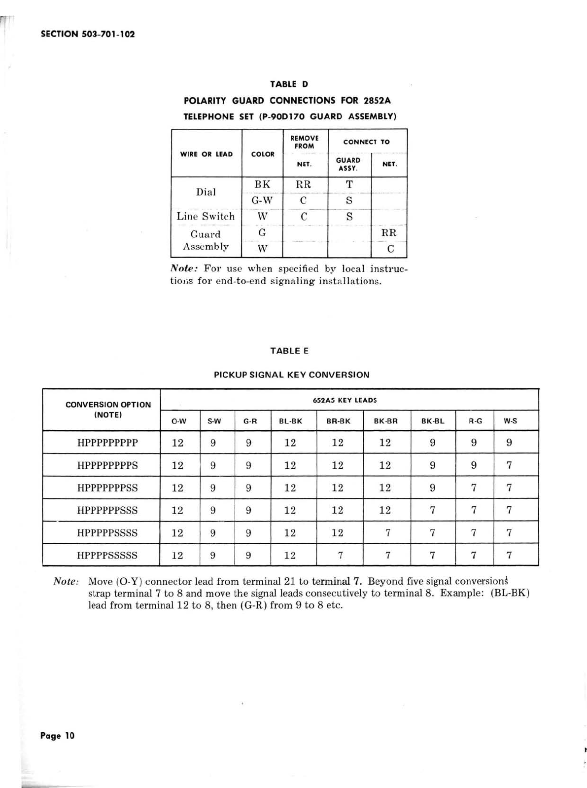
3.18
Polarity
Guard
(2852A only): Should be
used only when specified by local instructions
for end-to-end signaling installations where
battery
and
ground
reversals
may
be
encountered.
A
P-90D170 polarity
guard
assembly may be installed
on
the chassis below the dial.
3.19 Operational
tests
of
all
features
should be
made to insure proper operation and customer
satisfaction.
3.20 Where conditions
warrant,
the G3A6
handset
supplied with these
sets
can be replaced with
other types as follows:
•
For
impaired
hearing
-G6-type
Page
4
•
For
weak speech -G7-type
•
For
noisy location -G8-type
or
D-180413
Refer
to Division 501
for
connections
of
these
handsets.
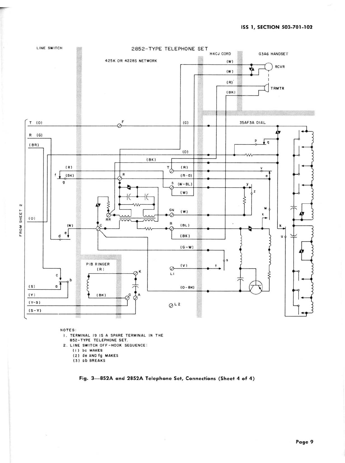
4.
CONNECTIONS
~
Due
to
the
liInited
number
of
conductors
~
the
852A
and
2852A
telephone
sets
do
not
follow
standard
wiring
an-angements.
4.01
To
provide connector leads
fer
illuminating
the HOLD button, the
ringer
or
buzzer leads
must
be used, meaning only two
of
the
three
options
(ringer, buzzer,
or
hold lamp) may be provided
at
the same time.
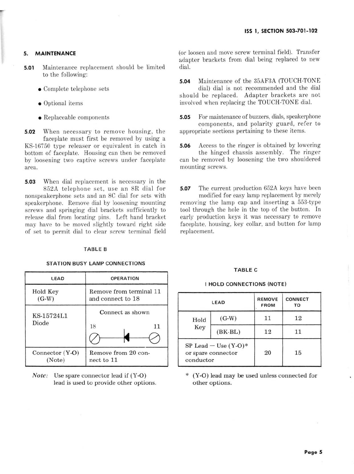
4.02 To provide
station
busy
lamp, modify
the
telephone
set
per
Table
B.
The KS-15724L1
diode is
used
to
prevent
false
busy
signals
and
must
be ordered and installed separately.
4.03 To provide
priority
hold
(I
HOLD) modify
the telephone
set
per
Table
C.
4.04 To provide individual signaling, modify the
telephone
set
by
converting
the
proper
button(s) and make wiring
changes
per
Table E.
The
key
and
its
associated
cord
assembly
are
adaptable for individual signaling
but
not for common
signaling.
4.05 To
provide
3-type
speakerphone
leads
in
the connector cable, the buzzer leads along
with the lamp and lamp ground leads from the 8th
and 9th pick-up key position
must
be used. Refer
to Table Ffor connections.
4.06 Connections
in
Table G
are
used when the
control unit
is
located close to the telephone
set
and
a
D10R
mounting
cord
is
used
as
an
auxiliary cord for connecting the 3-type speakerphone
leads to the telephone set. With this
arrangement
the
transmitter
and loudspeaker may be connected
directly to the control unit.
4.07
To
provide 4-type speakerphone connections,
connect
the
M16C cord as shown
in
Table
H.
'.,