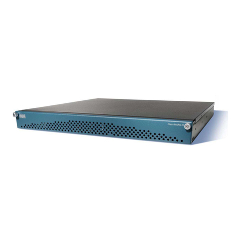
Beluk BLR-Q(U)06/12R User manual

Technical Documentation Rev. 01
Power Factor Regulator BLR-Q(U)
Beluk GmbH
Taubenstrasse 1
D- 6956 Schongau
Germany
Tel.: +49/(0) 61/2332-0
Fax: +49/(0) 61/2332-22
e-mail: blr@beluk.de
http://www.beluk.de
REFERENCE GUIDE
POWER FACTOR REGULATOR
BLR-Q(U)

Technical Documentation Rev. 01
Power Factor Regulator BLR-Q(U) Page 2 of 39
Revisionlist
Datum Name Revision Kommentar
25.07.12 Le 01 initial do ument release
Important Notice:
BLR-Q(U) with option –DM in ludes a re hargeable battery to run the real-time lo k. To repla e this battery,
please send the relay to Beluk. We will forward this battery to a re y ling system.
Important information!
If the sign aside appears besides a text passage in the manual the reader is strongly
advised to read the corresponding information as it is very important for the device
usage! It can contain safety advice or other information for the correct handling of the
device. If the information is disregarded, the device may be inoperable or even damaged!
!

Technical Documentation Rev. 01
Power Factor Regulator BLR-Q(U) Page 3 of 39
Contents
Contents
........................................................................................................................... 3
1 Installation and Conne tion........................................................................................... 5
1.1
Auxiliary voltage ...................................................................................................................................
1.2
Current measurement...........................................................................................................................
1.3
Voltage measuring ................................................................................................................................ 6
1.4
Control outputs ..................................................................................................................................... 6
1.
Alarm relay............................................................................................................................................. 7
1.6
Digital input............................................................................................................................................ 7
1.7
Digital output ......................................................................................................................................... 7
1.8
User Interface ........................................................................................................................................ 8
2 MENU BLR-Q(U)........................................................................................................... 9
2.1
MEAS. VALUES ..................................................................................................................................... 9
2.2
HARMONICS ........................................................................................................................................ 10
2.3
STEPINFO ............................................................................................................................................ 10
2.4
Quickstart SETUP ............................................................................................................................... 11
2.
MANUAL............................................................................................................................................... 29
2.6
DATALOGGER (option –DM).............................................................................................................. 30
2.7
DEVICE INFO ....................................................................................................................................... 30
3 Wiring diagrams BLR-Q(U) ......................................................................................... 31
3.1
BLR-Q(U)06/12R .................................................................................................................................. 31
3.2
BLR-Q(U)06/12T................................................................................................................................... 32
3.3
BLR-Q(U)12RT ..................................................................................................................................... 33
3.4
BLR-Q(U) I/O ........................................................................................................................................ 34
4 Standard Setting ......................................................................................................... 35
5 Trouble shooting ......................................................................................................... 37

Technical Documentation Rev. 01
Power Factor Regulator BLR-Q(U) Page 4 of 39
6 Te hni al Data ............................................................................................................ 38

Technical Documentation Rev. 01
Power Factor Regulator BLR-Q(U) Page 5 of 39
1 Installation and Connection
Only qualified staff is allowed to perform the installation. All legal rules have to be ob-
served and technical standards have to be met. Before connecting the device check that
all connecting leads are de-energized and that current transformers are bypassed.
1) Compare auxiliary-, measurement-, ontrol voltage, frequen y and the urrent path of the
devi e (see type label) with the data of the ele tri ity network.
2) Assemble the relay in the swit h panel with the 2 mounting lips. If the devi e is not fitting in
the utout the small plasti bars on the side of the ase an be removed with a knife.
3) Conne t prote tive ground to the terminal link of the ase.
4) Conne t in a ordan e to the wiring diagram (see hapter " onne tion"). Pay spe ial atten-
tion to the ross se tion size of the CT onne tions! An integrated voltage observation with
regard to the auxiliary voltage in BLR-Q(U) guarantees a safety dis onne tion of the apa i-
tors in ase of undervoltage. It must be ensured, that auxiliary voltage is taken from the iden-
ti al phase as ontrol voltage for the onta tors, to guarantee that all swit hing elements are
safely swit hed off in ase of under voltage.
5) Remove short ir uit links of the urrent transformer before ommissioning!
1.1 Auxiliary voltage
At BLR-Q(U) auxiliary voltage has to be onne ted separately from measuring voltage. The terminals for
auxiliary voltage are marked with La, Lb and 0.
Terminal 0 has to be onne ted always. La and Lb are different tapping points of the transformer to allow the
usage with different voltage levels. The detailed onne tion depends on the devi e type and an be seen on
the sti ker at the rear side of the regulator.
1.2 Current measurement
BLR-Q(U) an be used in ombination with x/5Amp urrent transformer as well as with x/1Amp types. The
terminals for CT onne tion are marked with K (S1) and L (S2). CT has to be mounted in the way, that K
(P1) onne ted to the feeder from utility and L (P2) is onne ted to load.
Current measuring is ne essary for al ulation of ontrol deviation and apa itors sizes for rea tive power
regulation as well as for showing and monitoring different measuring values.
BLR-Q(U) an be used with summation transformer as well. To get proper fun tion, please pay attention to
orre t polarity of all CTs and to the orre t setting of CT-fa tor. The CT-fa tor for a summation transformer
an easily be al ulated by adding the single transformer ratios (e. g. 1000A/5A + 1000A/5A + 1000A/5A =
200 + 200 + 200 = CT-fa tor 600).
!

Technical Documentation Rev. 01
Power Factor Regulator BLR-Q(U) Page 6 of 39
1.3 Voltage measuring
Terminals Um1 and Um2 are used for voltage measuring. Effe tive range is 50V to 530V AC and 45Hz to
65Hz. Voltage measuring is ne essary for al ulation of ontrol deviation and apa itors sizes for rea tive
power regulation as well as for monitoring and prote ting apa itors against over- and undervoltage and
THD U and for showing different measuring values.
If voltage is out of toleran e (range an be set), all a tive steps are dis onne ted and the regulation stops.
Voltage has to be measured as standard either from L1-N or L2-L3. If measuring voltage is taken from L1-N
or from L2-L3, is dete ted automati ally by omparing the value of measuring voltage with the setting of
nominal voltage.
It’s also possible to measure voltage from other phases as above. In this ase either automati initialization
must run (2.4.5) or the orre t setting for phase- ompensation (2.4.21.6) has to be done. Details of the fun -
tions an be found in the referring hapters.
1.4 Control outputs
BLR-Q(U) is available with up to 12 outputs. Depending on the regulator type the outputs an be relay out-
puts, transistor outputs or a mix between both types. The indi ation of the type an be found on the rear
sti ker either with the type des ription or the symbols of the output lamps.
If you have got the regulator type with mixed output steps, please pay attention that the clamp
A1 is the common root for the relay outputs 1 - 6 and clamp A2 is the common root for the
transistor outputs 7 - 12!
1.4.1 Relay outputs
The relay outputs of the power fa tor ontroller are designed for the dire t onne tion to onta tors. The
relay outputs are potential-free with one ommon root.
Maximum breaking apa ity for ohmi load: 250V AC / 5A, 400V AC / 2A, 110V DC / 0,4A, 30V DC / 5A.
Maximum fuse rating: 6A.
1.4.2 Transistor outputs
The transistor outputs of the power fa tor ontroller are designed for the dire t onne tion to thyristor swit-
hes. These open- olle tor outputs have got one ommon root. To trigger a thyristor swit h onne t (–) to
the root and (+) dire tly to the thyristor swit h.
Maximum breaking apa ity: 8-48V DC / 100mA
!

Technical Documentation Rev. 01
Power Factor Regulator BLR-Q(U) Page 7 of 39
1. Alarm relay
BLR-Q(U) is equipped with an alarm relay to signal proper fun tion of the system. The alarm relay has one
C/O onta t. The ommon point is terminal M.
Between the terminals M and MO is the breaking onta t. This onta t is losed in alarm ondition or when
BLR-Q(U) is dis onne ted from voltage.
Between the terminals M and MS is the losing onta t. This is losed in proper ondition of the system.
The breaking apa ity is 3A / 250V AC.
The circuit diagram is in chapter 3.4!
1.6 Digital input
1.6.1 Digital input for alarm-system
BLR-Q(U) is equipped with a digital input for AC-voltage for alarm-system (50-250V AC, terminals DI1.1 and
DI1.2). Digital input an be a tive high or a tive low. The fun tion an be programmed in the menu "SETUP /
ALARM / DI INPUT" (2.4.25)
Following odes are possible in voltage ontrol mode:
00 = ontrol following to the hara hteristi
01 = entre os phi
10 = os phi ind
11 = os phi ap
More details for the programming an be found in hapter "ALARM". See circuit diagram in chapter 3.4!
1.7 Digital output
BLR-Q(U) is equipped with one digital output (terminals DO1 and DO2). This output is a potential-free los-
ing onta t. The breaking apa ity is 5A / 250V AC. The fun tion of this output an be programmed in the
menu "SETUP / ALARM" ( hapter 2.4.25). The circuit diagram is in chapter 3.4!

Technical Documentation Rev. 01
Power Factor Regulator BLR-Q(U) Page of 39
1.8 User Interface
User Interfa e of BLR-Q(U) is a graphi al LCD and a membrane keyboard with 4 softkeys.
LCD is split into 4 areas:
Top area: the two lines of top area are showing information about general status of the relay. In
Voltage control mode always the actual target power factor is shown. The readings
of this area are always available, independent from the menu whi h is used. The read-
ings of top area an be parametered in menu SETUP/DISPLAY.
The “sad fa e” indi ates that there are problems with the level of voltage or urrent.
The “happy fa e” indi ates that levels of voltage and urrent are ok.
The “serious fa e” indi ates setting PFC OFF or PFC FREEZE.
Status olumns: left and right olumn are showing the status of the ontrol exits.
Step 1, status: off, type: NORMAL or FAST
Step 2, status: off, type: NORMAL blo ked or FIX OFF
Step 3, status: off, type: FAULTY
Step 4, status: on, type: NORMAL or FAST
Step 5, status: on, type: FIX ON
Step 6, status: off, type: OFF, not available or PFC OFF
“NORMAL blo ked” an be aused by dis harging time (2.4.22.1)
“PFC OFF” an be aused by voltage out of toleran e (0 and 2.4.21.8), by relay is off due
to setting (2.4.6) or due to Alarm system (2.4.25).
Main area: the three lines of main area are for menu navigation and display of information
Softkey area: the softkey area shows the fun tion of the membrane-keyboard. Depending on the
opened menue, the fun tion is different.
1
2!
F
4
5!

Technical Documentation Rev. 01
Power Factor Regulator BLR-Q(U) Page 9 of 39
2 MENU BLR-Q(U)
2.1 MEAS. VALUES
This submenu shows the available measurement values in the main area of LCD. The
values an be hosen by pushing the ▲ / ▼-keys.
Available measuring values:
BLR-Q(U)
ULL (voltage phase – phase)
ULN (voltage phase – neutral)
THD U (THD voltage)
I ( urrent)
THD I (THD urrent)
P (total a tive power)
Q (total rea tive power)
S (total apparent power)
F (frequen y)
∆
∆∆
∆Q ( ontrol deviation in kvar)
T (temperature at rear side of the devi e)
PF (power fa tor Λ = P/S, kW/kVA)
CP ( osϕ)
OPH (operation hours of pf -relay)
APF (average power fa tor)
T-MAX (max. temperature)
WPI / WPE
( ounter a tive work import / export)
WQI / WQC
( ounter rea tive work indu tive / apa itive)

Technical Documentation Rev. 01
Power Factor Regulator BLR-Q(U) Page 10 of 39
2.2 HARMONICS
The BLR-Q(U) is permanently al ulating the harmoni s of the voltage and urrent by
using Fourier transformation. After sele ting the submenu these values are displayed
separated in even and odd harmoni s of urrent and voltage in main display area. Every
displayed value is related to the fundamental wave.
Sele tion an be done by pushing the ◄►-key.
S rolling is possible by pushing the ▲ / ▼-keys.
2.3 STEPINFO
Stepinfo shows the information, whi h is saved in step database. By pushing + -key, the
step an be sele ted. By pushing ▼-key, the different saved values an be sele ted.
These values are: type of step, swit h y les, a tual apa itor size and derating of apa i-
tor in per ent.
2.3.1 STEP TYPE
Different types of steps are possible. With ex eption of the type FAULTY, the types an be set in
SETUP/STEPS (2.4.22.2).
Possible types are:
• NORMAL = step is used for normal regulation
• FIX-OFF = step is permanently swit hed-off
• OFF = step is permanently swit hed-off an blend out
• FIX-ON = step is permanently swit hed-in
(step will be swit hed-off in riti al situations like over- and undervoltage,
overtemperature or ex essive harmoni s)
• FAST = step is used for real-time algorithm. More information an be found in
hapter 2.4.22.2 and 2.4.23.
• FAULTY = the step is dete ted as defe tive and is blo ked
2.3.1.1 FAULTY STEPS
The dete tion of faulty steps is only possible, when the automati step re ognition is a tive (2.4.23.5) and
swit h y le is at least 1 se . When swit h y le is less 1 se step re ognition is automati off. A step is
“FAULTY”, when BLR-Q(U) annot dete t any hange of rea tive power at three swit hing operations in
series of this step.
Faulty steps are signed with "F!" in the status olumns. Furthermore the step type "FAULTY" is shown. De-
fe tive steps are blo ked for the regulation. Faulty steps an be reset in SETUP/RESET (2.4.28.2), by inter-
ruption of supply voltage of BLR-Q(U) or automati ally after 24 hours. Afterwards the step is used again for
its regular ontrol fun tion.

Technical Documentation Rev. 01
Power Factor Regulator BLR-Q(U) Page 11 of 39
2.3.2 SWITCH CYCLES
BLR-Q(U) is ounting and showing the swit hing y les of ea h step. This value allows the on lusion about
the a tual state of the onta tors. Swit h y les an be preset separately for ea h step in SETUP/STEPS
(2.4.22.3). Swit h y les of all steps is also reset, by a reset of omplete apa itor database in
SETUP/RESET (2.4.28.3).
2.3.3 STEPVALUE
As standard, the STEPVALUES are dete ted automati ally during operation. They are rated to the setting of
nominal voltage. In some spe ial appli ations, it is required to set the step values manually. This an be
done in SETUP/STEPS (2.4.22.4).
The STEPVALUE is showing the size of the apa itor, whi h is used for rea tive power regulation. The fun -
tion of this value an be ompared with the /k value of power-fa tor ontrol relays of former generations.
The STEPVALUE is shown in kvar. Ea h step has its own STEPVALUES, at BLR-Q(U) it’s one per step.
Step database is working with two values of apa itor size. The value whi h is shown in kvar is the a tual
value. This is ontinuously orre ted with every swit hing operation. A se ond value is saved after the first
ten swit h y les of ea h step after a reset of step database. This value indi ated the original available
STEPVALUE. This value is used to al ulate the per entage of a tual stepvalue to original stepvalue. This
per entage gives very simple information about derating of the apa itor banks.
2.3.3.1 When automatic step recognition is not active, the percentage is not shown (2.4.23. ).
2.4 Quickstart SETUP
In this submenu basi settings an be made for the BLR-Q(U). These settings are ne es-
sary for orre t fun tion and for orre t display of the measurement values. This menu an
be entered without password.
The following parameters an be set in Qui kstart menu:
2.4.1 CHANGE LANGUAGE
Standard version of BLR-Q(U) is supporting English, German and Fren h.
2.4.2 NOMINAL VOLTAGE
Fun tion of the setting of nominal voltage is to make a definition about the nominal voltage of the system.
This nominal voltage is valid for normal ontrol mode and voltage ontrol mode. The threshold levels for
under- and overvoltage are based on this as well as the ratings of the apa itor sizes in step database,
whi h are used for ontrol and monitoring (0 and 2.4.21.8). The apa itor sizes, whi h are stored in step
database, are also rated to the nominal voltage.
Independent of connection of the voltage measuring channel, nominal voltage is always the
phase-phase voltage!
!

Technical Documentation Rev. 01
Power Factor Regulator BLR-Q(U) Page 12 of 39
2.4.3 CT FACTOR
The CT FACTOR is the ratio of urrent transformer. (e. g. 1000/5 = ratio 200). At BLR-Q(U)3phase the CT-
Fa tor is used for all three urrent hannels.
For current measuring a CT always have to be used!
2.4.4 VT-FACTOR
VT FACTOR is the ratio of the voltage transformer. If the regulator is onne ted dire tly to the measurement
voltage without VT the value 1 has to be used
2.4.5 START AI
Automati initialization is swit hing all exits. During this test it an get information, whi h exits are working
and it an orre t the onne tion of the measuring hannels for voltage and urrent by internal settings.
Automati initialization an be started only when the “happy fa e” is shown (voltage and urrent are ok) and
when CONTROL is not set to satus OFF or FREEZE manually or by alarm-system. BLR-Q(U)3phase needs
at least one 3ph. Capa itor-bank for AI! If CONTROL setting is FREEZE done by AI, then a resart is possi-
ble.
When AI is running, the status line of BLR-Q(U) shows the message: “AI ACTIVE”. The maximum number of
swit hing operations during AI is 10 per exit (normally between 2 and 5). AI is taking are about the setting of
dis harge time for ea h exit. If there is a very long dis harge time ne essary, AI will take a ertain time.
The following messages from AI are possible:
-
ALARM: AI OK
AI is finished ompletely. Please he k if all used exits are shown with their number in the
display and please he k if BLR-Q(U) is working orre tly.
-
ALARM: CHECK CTs (only BLR-Q(U)3phase) (CONTROL setting is: FREEZE)
Following reasons are possible:
Rotary field of urrent measuring is not lo kwise or one or two urrent paths have wrong
polarity.
-
ALARM: STEPS (CONTROL setting is: FREEZE)
Capa itors annot be dete ted, be ause they are not ontrolled by ontroller or the rating is
smaller as limit.
BLR-Q(U)3phase: there is no 3ph. apa itor bank available!
-
AI ABORTED (CONTROL setting is: FREEZE)
AI ouldn’t be finished. The reason ould be permanent load variation during AI. Please try it
again or do the settings manually.
AUTOMATIC INITIALIZATION is only able to work, when capacitors are used for compensation.
If BLR-Q(U) has to switch reactors for compensation of capacitive load, this feature will cause
failures. AI is working at best, when there are stable load conditions!
!
!

Technical Documentation Rev. 01
Power Factor Regulator BLR-Q(U) Page 13 of 39
2.4.6 CONTROL ON / FREEZE / OFF
ON: Automati ontrol is running
FREEZE: Automati ontrol is stopped; status of exit relays is frozen
OFF: Automati ontrol is stopped; all exit relays are off
2.4.7 osϕ 1
This is the setting for target osϕ 1. It will be valid during normal operation.
2.4.8 SWITCH INTERVAL
The swit h interval is the time delay between swit hing steps in regulation.
The swit h interval has two different fun tions:
• Prote ting the onta tors by redu ing the number of swit hing y les.
• Building of the average of the rea tive power in the time of the swit h interval.
Step recognition is automatically set OFF, when switch interval is off.
In regulation mode LIFO, minimum switching interval is 1 sec longer, as the longest discharging
time. In HV-version, the minimum switching time delay is 8.7 sec.
2.4.9 STEPS
2.4.9.1 STEP TYPE
For every single step its fun tion an be defined separatly. You an sele t between the following fun tions:
• NORMAL = step is used for normal regulation algorithm
• OFF = step is permanently swit hed of an blend out in step indi ation
• FIX-OFF = step is permanently swit hed off
• FIX-ON = step is permanently swit hed on (step is supervised and also swit hed
off in riti al situations)
The step type "Fast" in only available for BLR-Q(U) with transistor exits. Steps, which are set "Fast"
(only possible for transistor exits) are not available for the normal regulation algorithm. For each
"Fast" step a nominal value has to be set, because the automatic step size detection is disabled in
real time algorithm.
• FAST = step is used for the real time algorithm. All needed steps to rea h the target
osϕ are swit hed simultaneously. There is no delay for swit hing.
Not used output steps have to be set to "FIX-OFF" or "OFF". So it is ensured, that these steps
are not used for the regulation anymore. No needless alarms are caused! Fix steps are labelled
by the permanent symbol "!" next to the step number! Steps there are set "OFF" are blend out.
!
!

Technical Documentation Rev. 01
Power Factor Regulator BLR-Q(U) Page 14 of 39
2.4.9.2 DISCHARGE TIME
For every single apa itor step an own dis harging time an be defined. The dis harging time is a blo king
time, be oming a tive after swit hing off a step. As long as this time is running (display of "!" in the step indi-
ation) this step is not available for the regulation. Dis harging time should be adapted to the apa itor dis-
harging unit.
For step exits, whi h are swit hing thyristor swit hes, dis harging time an be redu ed to the zero.
2.4.10 Cos phi ontrol
Swit h on or off voltage ontrol
COS PHI : U ontrol rea tive power depending on the voltage
COS PHI : P ontrol rea tive power depending on the load
NO : standard power fa tor ontrol
The following items appears only when the cos phi control is set to COS Phi : U, otherwise the points
are not visible.
2.4.11 COS PHI CAP
Defines the apa itive limit for the voltage ontrol.
2.4.12 COS PHI : U SET POINT 1
Defines target point 1 for the COS PHI : U / COS PHI : P ontrol
SET POINT 1 uses the “COS PHI CAP” when the measured voltage is at the level whi h is adjusted. In fa -
tory setting this point is used when 0.98 * NOM. V
2.4.13 COS PHI CENTER
Defines the enter point of the hara hteristi given by the adjusted SET POINT’s 1-4
2.4.14 COS PHI : U SET POINT 2
Defines an further point on the hara hteristi build between SET POINT 1 and SET POINT 4. This is also
adjusted by a voltage Level
2.4.15 COS PHI : U SET POINT 3
Defines an further point on the hara hteristi build between SET POINT 1 and SET POINT 4. This is also
adjusted by a voltage Level
2.4.16 COS PHI IND
Defines the indu tive limit for the voltage ontrol.

Technical Documentation Rev. 01
Power Factor Regulator BLR-Q(U) Page 15 of 39
2.4.17 COS PHI : U SET POINT 4
Defines target point 4 for the COS PHI : U / COS PHI : P ontrol
SET POINT 4 uses the “COS PHI IND” when the measured voltage is at the level whi h is adjusted. In fa -
tory setting this point is used when 1.06 * NOM. V
2.4.18 SETUP
In this submenu advan ed settings an be made for the BLR-Q(U). These settings are
ne essary for individual parametring for spe ial appli ations. To enter this submenu,
please push the right button for 3 se . It is prote ted by a password (fa tory setting 2402).
The menu is divided into logi al groups. In these groups you an find paramters whi h are also in Qui kstart
SETUP. The following points explain the settings.
2.4.19 CHANGE LANGUAGE
Standard version of BLR-Q(U) is supporting English, German and Fren h.
2.4.20 START AI
See Chapter 2.4.5
2.4.21 MEASUREMENT
2.4.21.1 CT-FACTOR
The CT FACTOR is the ratio of urrent transformer. (e. g. 1000/5 = ratio 200). At BLR-Q(U)3phase the CT-
Fa tor is used for all three urrent hannels.
For current measuring a CT always have to be used!
2.4.21.2 VT-FACTOR
VT FACTOR is the ratio of the voltage transformer. If the regulator is onne ted dire tly to the measurement
voltage without VT the value 1 has to be used.
2.4.21.3 NOMINAL VOLTAGE
Fun tion of the setting of nominal voltage is to make a definition about the nominal voltage of the system.
The threshold levels for under- and overvoltage are based on this as well as the ratings of the apa itor
sizes in step database, whi h are used for ontrol and monitoring (0 and 2.4.21.8).
Independent of connection of the voltage measuring channel, nominal voltage is always the
phase-phase voltage!
2.4.21.4 CONNECTION MEASUREMENT
CONNECTION MEASUREMENT the setting if measuring of voltage is onne ted between two phases or
between phase and neutral phase. It is normally dete ted automati ally at every start of BLR-Q(U). This is
done by omparing the setting NOMINAL VOLTAGE and the real measured voltage.
!
!

Technical Documentation Rev. 01
Power Factor Regulator BLR-Q(U) Page 16 of 39
The sele tion an also be done manually by pushing the ◄► button. The types, "U=L-N" or "U=L-L" are
available.
2.4.21. SYNCHRONISATION FREQUENCY
For a high pre ision of the measurement, the sampling rate has to be syn hronized to the frequen y of the
grid. Caused by ommutation not hes of mainsvoltage it is possible that the automati syn hronizing will not
work reliable. This reates failures in measurement. To avoid these problems, the following settings an be
done:
Automatic synchronizing:
For best measurement results, when mainsvoltage is without ommutation not hes.
FIX- 0HZ: For a safe operation at 50Hz grid with bad mains quality.
FIX-60HZ: For a safe operation at 60Hz grid with bad mains quality.
2.4.21.6 PHASE COMPENSATION
The phase ompensation enables the user to onne t the urrent- and voltage measurement hannels in
any way. This ompensation angle omplies with the phase angle between onne ted a tive urrent and
voltage. The following table shows the settings for some different onne tion types. This setting has to be
made correct, because otherwise correct regulation is not possible! If the current transformer is
connected inverted, additionally a phase compensation of 180° has to be respected.
Voltage
L1
-
N
L2
-
N
L3
-
N
L1
-
N
L2
-
N
L3
-
N
L1
-
N
L2
-
N
L3
-
N
Current transformer
L1 L2 L3 L2 L3 L1 L3 L1 L2
Conne tion U=L-N
U=L-N
U=L-N
U=L-N U=L-N U=L-N U=L-N U=L-N U=L-N
Phase-Offset 0° 0° 0° 240° 240° 240° 120° 120° 120°
Voltage
L2
-
L3
L3
-
L1
L1
-
L2
L2
-
L3
L3
-
L1
L1
-
L2
L2
-
L3
L3
-
L1
L1
-
L2
Current transformer
L1 L2 L3 L2 L3 L1 L3 L1 L2
Conne tion U=L-L U=L-L U=L-L U=L-L U=L-L U=L-L U=L-L U=L-L U=L-L
Phase-Offset 0°+90°
0°+90°
0°+90°
240°+90°
240°+90°
240°+90°
120°+90°
120°+90°
120°+90°
2.4.21.7 V-TOLERANZ MIN
The setting has to be done in per ent related to the nominal voltage. If the measurement voltage falls below
the adjusted limit, all a tive steps are swit hed off and the regulation stops.
2.4.21.8 V-TOLERANZ MAX
The setting has to be done in per ent related to the nominal voltage. If the measurement voltage ex eeds
the adjusted limit, all a tive steps are swit hed off and the regulation stops.
2.4.21.9 COUNTDOWN START AI
YES = after starting BLR-Q(U), a ountdown is running. During this ountdown it is possible to start AI auto-
mati initialization by pushing <Enter>.
NO = the ountown is not shown. To start AI, you have to hoose Qui kstart SETUP.
2.4.21.10 TEMP. OFFSET
The temperature offset allows orre tion of temperature reading in a range -10°C to +10°C.

Technical Documentation Rev. 01
Power Factor Regulator BLR-Q(U) Page 17 of 39
2.4.21.11 CT TYPE 1A
This setting hanges some internal threshold levels, to optimize the fun tion with 1Amp CTs.
2.4.22 STEPS
Settings on erning the step data base an be found in this submenu. The following settings are possible:
2.4.22.1 DISCHARGE TIME
For every single apa itor step an own dis harging time an be defined. The dis harging time is a blo king
time, be oming a tive after swit hing off a step. As long as this time is running (display of "!" in the step indi-
ation) this step is not available for the regulation. Dis harging time should be adapted to the apa itor dis-
harging unit.
For step exits, whi h are swit hing thyristor swit hes, dis harging time an be redu ed to the zero.
2.4.22.2 STEP TYPE
For every single step its fun tion an be defined separatly. You an sele t between the following fun tions:
• NORMAL = step is used for normal regulation algorithm
• OFF = step is permanently swit hed of an blend out in step indi ation
• FIX-OFF = step is permanently swit hed off
• FIX-ON = step is permanently swit hed on (step is supervised and also swit hed
off in riti al situations)
The step type "Fast" in only available for BLR-Q(U) with transistor exits. Steps, which are set "Fast"
(only possible for transistor exits) are not available for the normal regulation algorithm. For each
"Fast" step a nominal value has to be set, because the automatic step size detection is disabled in
real time algorithm.
• FAST = step is used for the real time algorithm. All needed steps to rea h the target
osϕ are swit hed simultaneously. There is no delay for swit hing.
Not used output steps have to be set to "FIX-OFF" or "OFF". So it is ensured, that these steps
are not used for the regulation anymore. No needless alarms are caused! Fix steps are labelled
by the permanent symbol "!" next to the step number! Steps there are set "OFF" are blend out.
2.4.22.3 SWITCH CYCLES
The number of swit h y les an be orre ted or reset for e h step separately.
!

Technical Documentation Rev. 01
Power Factor Regulator BLR-Q(U) Page 1 of 39
2.4.22.4 STEP NOMINAL VALUE
If STEP RECOGNITION is not a tive, it is required to do this setting, to get proper fun tion of the relay.
STEP RECOGNITION is not a tive for “Fast” steps or if it is blo ked (2.4.23.5) or for swit h y les less 1
se .
The size of the apa itors an be programmed manually in kvar.
The programming an be done for ea h step individually in kvar. So there is no spe ial sequen e ne essary.
A step an be programmed as a apa itor ( ) or as an indu tor (i). If you plan to use a mixed mode between
apa itors and indu tors, please onta t Beluk to get more information.
At BLR-Q(U)3phase capacitor size has to be programmed for each phase individually.
A three phase capacitor with 2 kvar has to be programmed with 8,3kvar for each phase!
2.4.22. STEP RESET
Sele ting this point all step sizes an be reset individually.
2.4.23 CONTROL
General explanations for a better understanding:
Cos phi control is using “NORMAL” steps. The target of regulation of normal algorithm is al ulated by tar-
get osϕ and apparent power of fundamental wave. The ontrol deviation is a mean value over the periode
of SWITCH INTERVAL (adjustable).
Voltage control
General working principle of BLR-Q(U)
The ontroll target is the voltage adjusted at "NOM. V", whi h must be the voltage on primary side. In ase
the voltage is droping/rising, the BLR-CM(Q) is swit hing in/out apa itor steps to in rease/de rease the
voltage again.
This is be done following to the above hara hteristi .
For better understanding all adjustable points are explained below:
"COS PHI CAP" is the apa itive border of the hara hteristi and will be used togehter with "SET POINT 1".
As example, when you've adjusted "SET POINT 1 0.96 NOM.V" and "COS PHI CAP 0.90" the regulator will
use target power fa tor 0.90 in ase the measured voltage is 10560V instead of 11000 ("SET POINT 1 0.96
NOM.V" = 0.96 * 11kV =10560).
"COS PHI CENTER" is just the enter point of the hara hteristi and is used when the voltage does not
deviate from adjusted "NOM. V".
"COS PHI IND" is the indu tive border of the hara hteristi and will be used togehter with "SET POINT 4".
As example, when you've adjusted "SET POINT 4 1.08 NOM.V" and "COS PHI IND i0.95" the regulator will
use target power fa tor i0.95 in ase the measured voltage is 11880V instead of 11000 ("SET POINT 4 1.08
NOM.V" = 1.08 * 11kV =11880V).
The "SET POINT 2" and "SET POINT 3" working with the same al ulation as "SET POINT 4" and "SET
POINT 1".
They an be just used to build an area where the voltage is not orre ted.
!

Technical Documentation Rev. 01
Power Factor Regulator BLR-Q(U) Page 19 of 40
Between the adjusted "SET POINTS" the ontroll target is al ulated dynami ally as shown in the below
drawing.
This means finally that the "TARGET POINTS" are just fixing the hara hteristi , the remaining tasks are
done automati ally

Technical Documentation Rev. 01
Power Factor Regulator BLR-Q(U) Page 20 of 39
Regulation mode normal algorithm: 4 different regulation modes are available at BLR-Q(U) for standard
os phi ontrol, in voltage ontrol this settings does not work:
1. Auto: The ontroller is working with the prin iple of „Best Fit“. Before a swit hing operation, all a-
pa itor-sizes in step database are ompared with ontrol deviation. The available step whi h gives
the best results will be swit hed.
2. LIFO: “Last In, First Out” The ontroller starts with regulation with step 1 and is swit hing further ex-
its step-by-step. Swit hing-off is done vi e versa.
3. Combined Filter: Spe ial algorithm for ombined filter banks with two different detuned ratings. The
ontroller is working like in automati mode with the prin iple “Best Fit”. From odd numbered steps,
there is at least or more of the apa itan e onne ted as from even numbered steps.
4. Progressive: Similar to Auto mode. When ontrol deviation is bigger as the biggest available step,
the all further steps are swit hed in intervals of two se onds. If the setting of swit h interval is less
two se onds, all further steps are swit hed in intervals of one se ond.
Sensitivity: (swit hing threshold) Sensitivity is the swit hing threshold for swit hing-on or swit hing-off the
apa itors in per ent (%). The range of the sensitivity an be between 55% and 100% (fa tory setting is
60%. Due to this, the in following explanation 60% is used.).
Sensitivity is used for two he ks:
1. The ontroller is using sensitivity to he k, if a swit hing operation is ne essary or if it’s possible.
If the demand for ompensation is bigger as 60% of the smallest for regulation available step, BLR-
Q(U) is sele ting from step database, if there are suitable steps to swit h.
2. To avoid hunting, the ontroller is only using steps, whi h will not overshoot more than 40% (100%-
60%) of its size.
Step exchange: Step ex hange is supporting automati ontrol and ombined filter ontrol algorithm to
rea h an optimum result. If the ontroller dete ts that target-pf is not rea hed it starts sear hing for a step
whi h gives better results. If step ex hange is a tive, the ontroller an repla e a swit hed-in step against a
step whi h mat hes better, to rea h the target.
Switch cycle balancing: Swit h y le balan ing is taking are that steps with similar sizes (toleran e an be
programmed in per ent) are used in a way, that they have the same number of swit h y les. At sele tion of
suitable step for next swit hing operation, the values of swit h y les, whi h are saved in step database, are
ompared. A balan ed attrition of onta tors and apa itors is assured by this.
This manual suits for next models
3
Table of contents
Other Beluk Controllers manuals

Beluk
Beluk BLR-CM Training manual
Beluk
Beluk BLR-CX Installation and operation manual
Beluk
Beluk CX plus User manual

Beluk
Beluk BLR-CX User manual

Beluk
Beluk CX plus User manual

Beluk
Beluk CX plus User manual
Beluk
Beluk BLR-CX-R User manual
Beluk
Beluk BLR-CM 3 phase User manual

Beluk
Beluk BLR-CM Modbus Guide
Beluk
Beluk CX plus User manual
