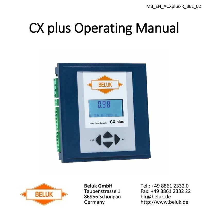
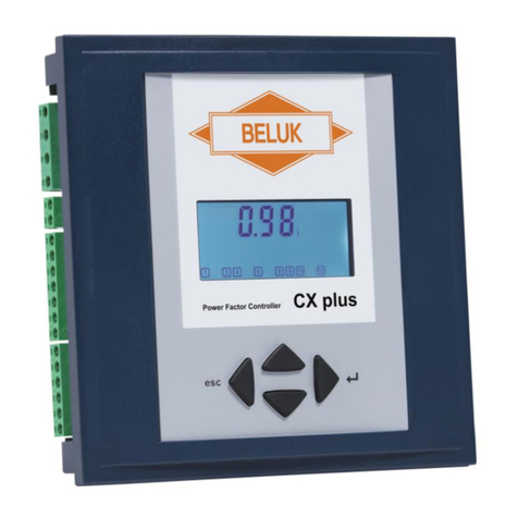
Beluk CX plus User manual

Technical documentation Rev. 02
Reactive Power Controller CX plus
Beluk GmbH
Taubenstrasse 1
D-86956 Schongau
Germany
Tel.: +49/(0)8861/2332-0
Fax: +49/(0)8861/2332-22
E-Mail: [email protected]
http://www.beluk.de
REFERENCE MANUAL
REACTIVE POWER CONTROLLER
CX plus

Technical documentation Rev. 02
Reactive Factor Controller CX plus
2
1Safety notes.................................................................................................................................... 3
2Installation and commissioning....................................................................................................... 5
3Wiring diagrams.............................................................................................................................. 6
3.1 List of options......................................................................................................................... 6
4Connection data.............................................................................................................................. 7
5Commissioning ............................................................................................................................... 9
6Questions during commissioning.................................................................................................. 10
7Indications on the display ............................................................................................................. 15
8Operation:..................................................................................................................................... 19
9Menu CX plus ............................................................................................................................... 21
9.1 Measurement value menu.................................................................................................... 21
9.2 INFO (step database)........................................................................................................... 24
9.3 MANUAL (manual operation: Manually switch steps on and off)......................................... 26
9.4 SETUP (setup menu)........................................................................................................... 28
9.5 Expert SETUP menu CX plus.............................................................................................. 31
9.6 100 Quick START setup ...................................................................................................... 33
9.7 200 Settings Measurement.................................................................................................. 35
9.8 300 Settings control ............................................................................................................. 37
9.9 400 Settings step database.................................................................................................. 41
9.10 600 RESET menu................................................................................................................ 51
9.11 700 Settings MODBUS (communication interface).............................................................. 52
9.12 Alarm memory menu............................................................................................................ 53
10 Technical specifications................................................................................................................ 55
11 Troubleshooting............................................................................................................................ 57
12 Applications................................................................................................................................... 63
12.1 Additional switching output for a step .................................................................................. 63
12.2 Fan activation....................................................................................................................... 64
12.3 Over-temperature switch-off steps....................................................................................... 65
12.4 THD-U / THD-I protection..................................................................................................... 66
12.5 Switching to target Cos 2 via the digital input................................................................... 67
12.6 Suppression of the I-LOW alarm by the digital input ........................................................... 67
12.7 Detection of step power loss (Step Power Loss)................................................................. 69
13 Identification / manual entry of step sizes..................................................................................... 70
13.1 Step identification is activated –Automatic identification of the step size........................... 70
13.2 Problems regarding the step identification........................................................................... 70
13.3 Step identification is deactivated / manual entry of the step sizes ...................................... 71
14 Identification / resetting of defective steps.................................................................................... 72
15 Adding additional steps................................................................................................................. 72
16 Automatic distribution of switching operations to steps................................................................ 73
16.1 Distribution of the switching operations via the switching cycles......................................... 73
16.2 Distribution of the switching operations via the operating hours.......................................... 73
17 Automatic initialisation .................................................................................................................. 73
17.1 Procedure of the automatic initialisation .............................................................................. 74
17.2 Problems during the AI / cancellation of the AI.................................................................... 75
18 Control algorithm........................................................................................................................... 76
18.1 BEST FIT (AUTO)................................................................................................................ 76
18.2 LIFO ..................................................................................................................................... 77
18.3 Combi filter........................................................................................................................... 77
18.4 Progressive .......................................................................................................................... 78
18.5 FIFO..................................................................................................................................... 78
19 Transformer compensation........................................................................................................... 80
19.1 Setting of the offset reactive power:..................................................................................... 80
19.2 Mixed measurement:............................................................................................................ 81
20 Default and customer settings ...................................................................................................... 82
21 Revision list................................................................................................................................... 84
22 Annex............................................................................................................................................ 84
22.1 Setting of phase correction angles depending on the connection....................................... 84
22.2 Connection in case of mixed measurement......................................................................... 84

Technical documentation Rev. 02
Reactive Factor Controller CX plus
3
1 Safety notes
Read these safety notes and instructions attentively and carefully first. Familiarise yourself with the
device prior to installation, commissioning and operation. The following symbols are used in the
manual and on the device label on the back of the device in order to indicate dangers and problems or
to give specific instructions.
!DANGER
DANGER indicates a dangerous situation which, if not avoided, may cause death or severe
injuries.
!WARNING
WARNING indicates a dangerous situation which, if not avoided, may cause death or severe
injuries.
!CAUTION
CAUTION indicates circumstances which may damage or destroy the device in case of non-
observance, but do not cause injuries.
NOTE: Further information in order to describe special technical features
in a more detailed way.

Technical documentation Rev. 02
Reactive Factor Controller CX plus
4
!DANGER
During the installation of the CX plus, there is a risk of electric shock. For this reason, installation,
commissioning and maintenance may exclusively be performed by a skilled electrician with the
necessary qualification. A skilled electrician is a person who has the ability, experience and
knowledge necessary for the construction, installation and operation of electrical equipment and
systems and who is trained in the detection and prevention of potential hazards.
During installation, the relevant regulations for the installation of switchgear and for the prevention
of accidents must be observed and complied with. Devices with damaged or open housing or
terminals may not be connected to the mains and must be disconnected immediately.
The current transformer must be short-circuited prior to disconnecting the current measurement
path at the device resp. at the current transformer. Otherwise, there may be a life-threatening
voltage at the connections of the current measurement path resp. of the transformer. In the long
run, the transformer will be destroyed by the high voltage.

Technical documentation Rev. 02
Reactive Factor Controller CX plus
5
2 Installation and commissioning
1) Before installation, the connection data of the CX plus must be compared with the data of the
supply network and of the installation.
2) The working area must be disconnected from voltage and secured against unauthorised and
unintentional restart. The absence of voltage must be verified with a standardised instrument /
testing device. The voltage-free system must be grounded and short-circuited. Adjacent live
parts must be covered and / or placed behind barriers.
3) The current transformer must be short-circuited. A current transformer that has NOT been
short-circuited generates very high voltages posing a danger to persons and equipment. The
current transformer can thereby be destroyed.
4) Disconnect and remove the old reactive power controller.
5) Plug the CX plus into the switch panel section and fix it with the two mounting brackets.
(Section 138 x 138 mm)
6) Connect the protective conductor at the PE terminal of the metal back of the CX plus.
7) Connect the connecting lines as per the wiring diagram (current transformer: K to power plant,
L to load).
8) Remove the current transformer jumper.
9) Switch on voltage.
10) With a proper connection and correct connection data, the display lights and all symbols are
visualised on the LCD in the course of a display test for 1 second.
11) The current transformer factor must be entered.
12) If necessary, also enter the correct nominal voltage and the voltage transformer factor.
13) Execute the “Automatic initialisation” (AI).
14) If the “Automatic initialisation” was successfully finished, the message AUTO appears on the
display. Control starts after the discharge time lock (default: 75 s).

Technical documentation Rev. 02
Reactive Factor Controller CX plus
6
3 Wiring diagrams
CX plus-12R
3.1 List of options
Designation
Explanation
CX plus
-06R
6 output / step relay
-12R
12 output / step relay
-MB
Modbus RTU –Connection via RS485 3-wire bus
-m
Signalling / alarm relay with break contact

Technical documentation Rev. 02
Reactive Factor Controller CX plus
7
4 Connection data
Measuring and supply voltage
Combined voltage measurement and supply
Range: 90 –550 V AC, 45 –65 Hz
Terminals: U1 / U2
A transformer factor can be set when using voltage transformers.
Range 1.0 –350.0
Current measurement
Current measurement
Range: 5 mA –6 A AC, 45 –65 Hz.
The use of x/1 and x/5 transformers is possible.
Terminals: S1 (K) / S2 (L)
Transformer factor adjustable from 1 –9600
Switching outputs relay
only option -xxR
Equipment with 6 (option: -06R) or 12 switching outputs (option: -
12R)
Switching outputs potential-free with common root
Terminals: C / 1 –12
Switching capacity 5 A / 250 V AC
Fan relay
Closes the contact when exceeding the pre-set temperature limit 1.
Terminals: F1 / F2
Switching capacity 5 A/ 250 V AC
The fan relay may be used alternatively as 7th or 13th switching
output for a step.
This function is described in more detail in the chapter
“APPLICATIONS”, paragraph “Additional switching output for
a step”.
Alarm relay
Normally open contact, closed in normal operating condition.
Opens in case of alarm and in case of a failure of the supply
voltage (life contact).
Terminals: AL1 / AL2
Switching capacity 5 A / 250 V AC
Digital input
Digital input either for switching to the second target cos or for
supressing the I-LOW alarm.
Adjustable logic: HIGH or LOW active
Terminals: I1 / I2
Input signal: 90 –250 V AC
Temperature measurement
internal NTC (under the housing cover)
MODBUS interface
only option: -MB
Protocol: MODBUS-RTU
Interface: RS485
Terminals: + / GND / -
TTL interface

Technical documentation Rev. 02
Reactive Factor Controller CX plus
8
Service interface. For service purposes only.
!CAUTION
Exception: The current transformer factor (SETUP/Ct) must be
entered in order to correctly calculate the measurement values
and to correctly identify the step sizes.

Technical documentation Rev. 02
Reactive Factor Controller CX plus
9
5 Commissioning
The CX plus is pre-programmed with default values, which enable an operation
almost without further settings, if connected to a 400 V supply network according to
the wiring diagram.
The measurement values of current and power are only displayed, if the current
transformer factor has been set.
NOTE: If the connection of measuring voltage and current results in a phase
between voltage and current not equal to 0° resp. 90°, execute the AUTO
INITIALISATION (AI) first or manually set the phase correction angle (setup menu:
206) correctly. The table with the phase correction angles depending on the
connection of measuring voltage and current can be found in the annex, paragraph
Setting of phase correction angles.
NOTE: The “Automatic initialisation” only identifies the correct phase between
measuring voltage and current. Furthermore, the AI determines which switching
outputs are occupied and which not. Switching outputs which are not occupied are
set to the step type “FOFF”. The step sizes are determined at first via the control in
the normal control mode.
After applying the mains voltage, the message “AUTO” appears on the display and
the currently measured COS is displayed, if measuring voltage and current are
within the tolerance. Normally, the COS should be inductive (display of a small i
behind the first line). From this moment on, the discharge time lock of the capacitors
is active (factory setting: 75 sec.). After the discharge time lock, the CX plus starts
controlling. In the process, the step sizes are determined automatically. Step outputs
which are not occupied are set to the step type “FOFF” (Fix-Off), if the first three
switching processes have been unsuccessful. I.e. the control ignores these steps.
!CAUTION
Exception: The current transformer factor (SETUP/Ct) must be entered in order to correctly
calculate the measurement values and to correctly identify the step sizes.

Technical documentation Rev. 02
Reactive Factor Controller CX plus
10
6 Questions during commissioning
1) “AUTO”is not displayed control stopped or switched off.
Possible causes:
Manual operation, control has been stopped or switched off in the setup menu.
Current is less than 5 mA, voltage of THD of voltage or current are out of tolerance, temperature is too
high, “Automatic initialisation (AI)” was cancelled with error.
Control is switched off
2) Display “U ALARM”measuring voltage out of tolerance
Possible causes:
Over- or under-voltage in the system, the set nominal voltage and the voltage transformer factor do
not correspond to the system.
Solution:
Check the settings for nominal voltage (SETUP/100/Un) and voltage transformer
(SETUP/100/Pt). The set voltage tolerance range is too small.
Solution:
Check the settings of the tolerance range (SETUP/204).
3) Display “I Lo ALARM”no current
Possible causes:
Connection from the current transformer to the controller is not correct; current transformer jumper is
not removed; transformation ratio of the transformer is too large current is less than 5 mA no
current
4) Display “EXPORT”feeding back of active power
There is no real feeding back, please check the connection of measuring voltage and current (phase,
polarity).
Possible causes:
The set phase correction angle does not correspond to the connection of measuring voltage and
current
Solution:
Correct the connection, execute the “Automatic initialisation (AI)” or manually set the phase
correction angle correctly.
Measuring voltage or current has been connected at a twisted angle of 180° from the direction of
connection (U2 / U1 instead of U1 / U2 resp. S2 / S1 instead of S1 / S2).

Technical documentation Rev. 02
Reactive Factor Controller CX plus
11
Solution:
Correct the connection, execute the “Automatic initialisation (AI)” or add 180° to resp. subtract
180° from the set phase correction angle (SETUP/206) (new angle < 360°).
Please observe the separate notes at the end of the chapter for the setting of the phase
correction angle.
Also see chapter “Automatic initialisation”
5) Incorrect “COS PHI“ is displayed incorrect connection
Incorrect phase between measuring voltage and current. Please check the connection of measuring
voltage and current (phase, polarity).
Possible causes:
The set phase correction angle does not correspond to the connection of measuring voltage and
current.
Solution:
Correct the connection, execute the “Automatic initialisation (AI)” or manually set the phase
correction angle correctly.
Measuring voltage or current has been connected at a twisted angle of 180° from the direction of
connection (U2 / U1 instead of U1 / U2 resp. S2 / S1 instead of S1 / S2).
Solution:
Correct the connection, execute the “Automatic initialisation (AI)” or add 180° to resp. subtract
180° from the set phase correction angle (SETUP/206) (new angle < 360°).
Please observe the separate notes at the end of the chapter for the setting of the phase
correction angle.
Also see chapter “Automatic initialisation“
6) Display “AI Abrt”The “Automatic initialisation” (AI) was cancelled with error.
Possible causes:
Heavy load fluctuations during the “Automatic initialisation (AI)”
Solution:
Restart the “Automatic initialisation (AI)”, when the mains is steadier. The measuring current
was too small.
The current transformer ratio may be too large.
Solution:
Check if the selected current transformer corresponds to the system and change it, if
necessary. Restart the “Automatic initialisation (AI)”.

Technical documentation Rev. 02
Reactive Factor Controller CX plus
12
The step sizes may be too small.
Solution:
Enter the phase correction angle (SETUP/206) manually and switch on the control again
(SETUP/100/PFC or SETUP/310).
If the “Automatic initialisation” (AI) is not successful after several attempts, it is alternatively
possible to manually set the correct phase correction angle (SETUP/206). The step outputs
which are not occupied can be set manually (SETUP/100/OUt) to the step type “FOFF”.
The control must be manually switched on again (SETUP/100/PFC or SETUP/310).
7) Step outputs are immediately switched off again.
Possible causes:
The nominal value of a step saved in the step database is not correct anymore (after changing a
capacitor, the value must be entered manually again or the entire step database must be reset).
Step is defective no step power identified during switching
Solution:
Check the fuses and power contactors.
(see chapter Step identification / defective steps)
8) One or several steps were identified as defective.
No step power identified during switching.
Possible causes:
Steps are defective
Solution:
Change the capacitors
Fuses are defective
Solution:
Change the fuses
Power contactor does not switch anymore or contacts are defective.
Solution:
Change the power contactor
(see chapter “Identification / resetting defective steps”)
9) Frequent switching of the outputs

Technical documentation Rev. 02
Reactive Factor Controller CX plus
13
Possible causes:
The initial values of the step power of the individual steps are still saved in the step database. By
switching the steps, the step powers of the individual capacitors are identified and saved in the step
database.
10) Identified step sizes are incorrect
Possible causes:
The set current transformer factor is incorrect
Solution:
Enter the current transformer factor correctly (SETUP/100/Ct), enter the step sizes manually
(SETUP/402) or reset the step database (SETUP/602).
Heavy load fluctuations during the step identification
Solution:
Enter the step sizes manually (SETUP/402) or reset the step database (SETUP/602).
The set phase correction angle does not correspond to the connection of measuring voltage and
current.
Solution:
Correct the connection, execute the automatic initialisation or manually set the phase
correction angle correctly.
11) Measurement values of current and power are not displayed.
Possible causes:
The current transformer factor was not set.
Solution:
Enter the current transformer factor correctly (SETUP/100/Ct).
12) Measurement values of current, power and step sizes are incorrect.
Possible causes:
The set current transformer factor is incorrect.
Solution:
Enter the current transformer factor correctly (SETUP/100/Ct), enter the step sizes manually
(SETUP/402) or reset the step database (SETUP/602).
!WARNING

Technical documentation Rev. 02
Reactive Factor Controller CX plus
14
Prior to disconnecting the current measurement path at the device resp. at the current
transformer, the current transformer must be short-circuited. Otherwise, there may be a life-
threatening voltage at the connections of the current measurement path resp. of the transformer.
In the long run, the transformer will be destroyed by the high voltage.
NOTE: In order to set the phase correction angle:
A table with the phase correction angles depending on the connection of measuring voltage and
current can be found in the annex, paragraph Setting of phase correction angles.
If the adding of 180° results in a phase angle equal to or greater than 360°, subtract 180° instead.
Example:
Previously set phase correction angle = 270°
270° + 180° = 450° greater than 360°
270° - 180° = 90° phase correction angle to be set

Technical documentation Rev. 02
Reactive Factor Controller CX plus
15
7 Indications on the display
The currently selected main menu is shown on the right
side of the display.
INFO: Step database
AUTO: Control is active: Steps are switched on and off
automatically.
MANUAL: Manual operation: Steps can be switched on and off
manually.
SETUP: Setup menu
ALARM: Alarm memory: The last 10 alarms can be shown here.
The current COS PHI is shown in the top menu level in the
first line of the display. The small iresp. cindicates, if the
COS PHI is inductive or capacitive. The codes for the
individual sub-points are shown in the submenus.
The settings and measurement values (in the middle) with
the respective abbreviation (on the left) and the units (on
the right) are shown in the second line of the display. In
case of an alarm, a message will be shown here. All
possible messages are listed and explained in the table on
the next page.
Active switching outputs are shown in the bottom line. If one step was
identified as defective (three unsuccessful switching operations), the
respective step symbol starts to flash. The step symbol of the selected
step is flashing in the step database and in the setup menu.
NT: 2nd target COS-PHI is active
EXPORT: Export (feeding back) of active power
ALARM: Flashes when there is an alarm message

Technical documentation Rev. 02
Reactive Factor Controller CX plus
16
In case of an alarm, an alarm message is flashing on the display in addition to the display “ALARM” at
the CX plus. The table below offers an overview of all possible alarm messages.
In order to reset the active alarms, keep the (ESC) key pressed for 3 s.
Alarm messages:
Measuring voltage is out of the set tolerance.
Measuring current is less than 5 mA (short-circuit
jumper may still be present at the current
transformer (K –L) or interruption in the current path
or current transformer ratio is too large).
Measuring current is too high.
The controller cannot reach the compensation
target.
The set limit for the THD of the voltage has been
exceeded. Steps will be or were already switched off
one by one.
The set limit for the THD of the current has been
exceeded. Steps will be or were already switched off
one by one.
/
One or several steps are defective. The step
symbols of the defective steps are flashing with the
alarm message.
The error codes Step and FLty are flashing
alternatingly.
/
The step power of one or several steps has dropped
below 75% of the initial power. Error code and step
number are flashing alternatingly. The affected steps
are switched off, set to the step type “FOFF” and are
locked for the control.
Only the smallest affected step number is displayed.

Technical documentation Rev. 02
Reactive Factor Controller CX plus
17
The second temperature limit has been exceeded.
Steps will be or were already switched off one by
one.
Set limit value of the operating hours has been
exceeded.
/
Set limit of the maximum permissible switching
cycles of one or several steps has been exceeded.
Error code and step number are flashing
alternatingly.
Only the smallest affected step number is displayed.
/
Set limit of the maximum permissible operating
hours of one or several steps has been exceeded.
Error code and step number are flashing
alternatingly.
Only the smallest affected step number is displayed.
If several alarms are active, the alarm messages are exchanged cyclically.
Example: U and I-Low alarm are active, the alarm messages are displayed as follows: 3 times error
code “U”, then 3 times “I”, then again 3 times starting with “U” etc.
In addition to the alarm messages, the following error and status messages are displayed.
Error messages:
/
The automatic initialisation (AI) was cancelled due to
an error. The control was switched off.
An active error message can be reset by pressing the (ESC) key for 3 s.

Technical documentation Rev. 02
Reactive Factor Controller CX plus
18
Status messages:
Temperature limit 1 has been exceeded; switching
output fan is switched on.
NOTE: The activation of the switching output fan
and the display of the fan message only occur, if the
function Use switching output FAN as step switching
output (SETUP/406) is deactivated (NO).
The control is switched off.
The control is stopped.
NOTE: Status messages cannot be reset by pressing the (ESC) key.
NOTE: Alarm messages are only displayed in the main menu. The menu items INFO, MANUAL,
SETUP or ALARM must not be selected.
NOTE: If the menus INFO, MANUAL, SETUP or ALARM are selected in the main menu, only error
and status messages are displayed.
NOTE: If the submenus INFO, MANUAL, SETUP or ALARM are active, no alarm, error or status
messages are displayed.
NOTE: The messages / , and are only displayed in the
main menu, when no alarm is signalled.
NOTE: Only one active error resp. status message is displayed.
The error message / has priority over the status messages and
resp. .
The status message has priority over the status messages resp.
.

Technical documentation Rev. 02
Reactive Factor Controller CX plus
19
8 Operation:
The CX plus is operated using 4 keys.
NOTE: If no key is pressed within 60 s, the backlighting is switched off. If the
backlighting is switched off, the backlighting is first switched on by pressing one of
the 4 keys.
There is only a reaction in the user menu when you press a key again.
Increase values, select the previous
measurement value, menu item and
step number
Exit menus,
moves the cursor to
the left,
reset alarms (keep the
key pressed for
approx. 3 s in order to
reset the alarm)
Open menus,
moves the cursor to
the right,
accept the set value
Reduce values, select the next
measurement value, menu item and
step number
Entering numerical values:
As the procedure for entering the numerical values is always the same, the input mask is described
beforehand:
The current value is shown on the display, while the first digit is flashing. By pressing
the keys "" and "", this digit can be increased or decreased. With the key "",
you can switch to the next digit in order to set the desired value with the keys ""
and "". With the key "", you can switch to the previous digit in order to set the
desired value with the keys "" and "". If you selected the last digit (on the right)
and you press the key "", you can set the multiplier k (kilo) or m (mega) with the
keys "" and "" in case of higher values, if necessary. In order to accept the value
and to finish entry, please press the key ""again.
If a set value was not accepted or if another value is displayed after the entry, it is possible that the set
value exceeded resp. fell below the limit of the setting range.

Technical documentation Rev. 02
Reactive Factor Controller CX plus
20
You may cancel the entry of a value at any time with the key "": Press the key "" until the first digit
(on the left) is selected. The entry is cancelled without accepting the new value by pressing the key
"" again.
Other manuals for CX plus
3
Table of contents
Other Beluk Controllers manuals

Beluk
Beluk BLR-CM Modbus Guide
Beluk
Beluk BLR-Q(U)06/12R User manual
Beluk
Beluk BLR-CX Installation and operation manual

Beluk
Beluk BLR-CX User manual
Beluk
Beluk CX plus User manual
Beluk
Beluk BLR-CM 3 phase User manual
Beluk
Beluk BLR-CX-R User manual
Beluk
Beluk CX plus User manual

Beluk
Beluk BLR-CM Training manual

Beluk
Beluk CX plus User manual
