Beluk CX plus User manual

Rev. 2.1
Beluk GmbH
Taubenstrasse 1
86956 Schongau
Germany
Tel.:
Fax.:
E-Mail:
Web:
User Manual CX plus

General safety notes
Failure to observe the following instructions may result in
serious injury or death!
There is a risk of electric shock during installation! Therefore, electrical devices
may only be installed, operated, serviced and maintained by qualified
professionals. A professional is someone who has the ability, experience and
knowledge required for the construction, installation and operation of
electrical equipment and who has been instructed in identification and
avoidance of possible hazards.
During installation and maintenance, the relevant regulations for the
installation of switchgear and accident prevention must be observed and
adhered to.
Devices with damaged or open housings or terminals must not be operated on
the power grid and must be disconnected immediately.
After disconnecting the device, 10 minutes must be waited until the capacitors
have been discharged. Subsequently, doors or covers may be removed. It must
be checked whether the disconnected area is voltage-free using a standardized
measuring instrument.
Ther BELUK GmbH assumes no responsibility or warranty for damage to
persons and equipment caused by improper installation and use.

Connection diagram: CX plus -12R
NOTE: The CX plus is designed to control capacitive or inductive stages.
Operating both stage types simultaneously is not possible.

Connection diagram: CX plus -12T
NOTE: The CX plus is designed to control capacitive or inductive stages.
Operating both stage types simultaneously is not possible.

Installation and commissioning
1) Before installation, the connection specifications of the CX plus must be
compared with the data of the power grid.
2) Disconnect the power supply and secured the working area against
unauthorized and unintentional reconnection. Check if the disconnected
area is voltage-free using a standardized measuring instrument. The
voltage-free system must be earthed and short-circuited. Neighboring live
parts must be covered and/or bypassed.
3) The current transformer must be short-circuited. A current transformer
which has not been short-circuited generates a life-threatening voltage.
This can lead to a destruction of the current transformer.
4) Insert the CX plus into the panel cut-out and fix it by using both fixing
clamps.
5) Connect the grounding cable to the intended terminal on the backside of
the device.
6) All cables must be connected as it is depicted in the connection diagram.
The terminal K of the current transformer must be connected to terminal
S1 and the terminal L to terminal S2.
7) Remove the short-circuit bridge at the current transformer.
8) The voltage can now be switched on.

9) If the device is connected correctly, the display will light up for one second
and all symbols will be displayed during a display test.
10) Now the First Setup can be started by confirming YES. The different
settings must be adjusted according to the power grid.
11) After a successful First Setup, the display shows AUTO. The control starts
after the set discharge time has been expired.

Frequently asked questions during commissioning
1) AUTO is not shown → control is switched off
Possible reasons: Manual operation activated; control is switched off;
temperature is too high; current is less than 5 mA; voltage or THD of the
voltage are inadmissible
2) U ALARM is shown → voltage is out of tolerance
Possible reasons: Nominal voltage (SETUP/Un) or voltage transformer
factor is set incorrectly (SETUP/Pt)
3) I Lo ALARM is shown → measuring current is smaller than 5 mA
Possible reasons: Connection from the current transformer to the
controller is incorrect; the current transformer jumper was not removed;
current transformer ratio is too large; no current flow
4) EXPORT is shown → reverse current flow
Possible reasons: If there is no real reverse current flow, the voltage or
current measurement is incorrect (phase, polarity)
5) Wrong cos ϕis shown → incorrect connection
Possible reasons: Voltage or current measurement is incorrect (phase,
polarity)
6) Outputs are immediately switched off
Possible reasons: Stage sizes in the stage database are incorrect
7) Frequent switching operations
Possible reasons: Capacitor capacity have not been recognized yet

Display
AUTO or
no display:
Measurement menu
INFO:
Stage database
AUTO:
Control is active (no menu item)
MANUAL:
Manual mode
SETUP:
Controller settings
ALARM:
Alarm memory
NT:
EXPORT:
ALARM:
Target-cos ϕ2 active
Reverse current flow
Flashes if an alarm is pending
First line
1: Power factor cos ϕ/ Menu item
2: Inductive i/ capacitive c
Second line
1: Abbreviations
2: Measurement values / alarm codes
3: Units
Stage outputs
Stage status:
On, off, faulty (flashing)
Stage data base:
Selected stage flashes
2
1
1
2
3

Operation concept
1
Exit menu
Move cursor to the left
Reset alarm (push for 3 s)
2
Decrease value
Select next value, menu or stage
number
3
Increase value
Select previous value, menu item or
stage number
4
Open menu
Move cursor to the right
Accept value

Entering values
If a menu item has been entered, the first digit of the current value flashes.
Numbers can be increased or decreased by pushing the and keys.
The next digit can be selected by pushing the key. In order to select the
previous digit, the key must be pushed.
If the last digit (right) has been selected and the key is pushed again, a
multiplier k(kilo) or M(mega) can be set using the and keys. To accept
the value and complete the entry, the key must be pushed again.
If an entered value has not been accepted, or if another value is displayed after
an input, the entered value has exceeded or fallen below the threshold of the
setting range.
An entry can be canceled at any time by pushing the key. Depending on the
actual position, the key must be repeatedly pushed until the first digit (left)
is selected. Pushing the key again exits the menu item without accepting
changes.

Main menu
A menu can be selected by pushing ; Submenus are entered with
Measurement menu (Using )
Retrieve measured values
INFO –Stage database
Contains the reactive power, power losses,
amount of switching cycles and operating hours,
stage type of each stage
MANUAL –Switching stages manually
Switching stage outputs manually
SETUP –Controller setup
Show and adjust all controller settings
ALARM –Alarm memory
Show the last 10 alarm messages. The newest
alarm message is saved in location 1.

INFO –Stage database
Stages can be selected by and entered by pushing . The selected stage
flashes. Using , the following information can be shown.
Current capacitor size
The reactive power value refers to the nominal
voltage
Capacitor size in percent
Current reactive power to nominal reactive
power ratio
Amount of switching cycles
Amount of completed switching operations
Stage type
AUTO: Stage is controlled automatically
FON: Stage is always on
FOFF: Stage is always off
Flty: Stage has been detected as faulty
Operating hours
Amount of operating hours

MANUAL –Switching stage outputs manually
In order to enter the MANUAL menu, the key must be pushed for
3 seconds.
to select a stage. The selected stage is
shown in the lower part of the display. A stage
is switched on or off by pushing the button.
The MANUAL menu can be exit by pushing the
key.
Important information:
Only stages of the type AUTO can be manually switched.
The discharge time is considerd in manual mode as well. After switching a
stage off, it is locked until the discharge time has been expired.
The measured voltage must be within the set tolerance. If the voltage is
out of tolerance, every stage is switched off and cannot be switched on
again.
As soon as the MANUAL menu is left, the control automatically starts
again.

SETUP –Controller setup
The Quick Start menu (100) and the Expert menus (200 –800) can be entered
by pushing the button. The latter one requires the input of a PIN code.
Un
Nominal voltage
Ct
Current transformer factor
Pt
Voltage transformer factor
Ai
Automatic initialization
The phase angle between voltage and current is determined and
which stage outputs are used.
PFC
Control ON, OFF, Hold
Switching on, off or suspend the control
CP1
Target-cosϕ1
Compensation target
St
Switching time
Delay between switching different stages
Out
Stage type AUTO, FON, FOFF, Flty
Stages are controlled automatically, are peramanetly on,
permanently off or detected as faulty. AUTO, FON and FOFF can be
adjusted and Flty stages can be reset.

Automatic initialization (Ai)
The Automatic initialization determines the phase angle between voltage and
current and detects which stage outputs are used.
The Automatic initialization can be activated in the SETUP menu
(SETUP/100/Ai or SETUP/207 = YES) and starts as soon as the voltage is within
the tolerance and the measured current is greater than 5 mA. The display
shows Ai run and the number of the active run. At the end of the Ai, the
function of the controller must be checked.
NOTE: The Automatic initialization is only possible in conjunction with
capacitive stages.
Due to load fluctuations, it may happens that the Ai does not correctly
recognize used stage outputs or is aborted. The latter one is displayed by the
error message Ai / Abrt. In this case, the control is stopped.
If the Automatic initialization is not successful after several attempts, the
correct phase correction angle must be set manually (SETUP/206). Moreover,
the stage types must be adjusted manually (SETUP/100/Out or SETUP/403)
and the control must be started again (SETUP/100/PFC or SETUP/310 = ON).

Automatic stage size detection
If stage detection is activated (SETUP/308 = YES), the CX plus determines the
size of the stages automatically during each switching operation. The detected
sizes are stored in the stage database. There, a stage power loss can be
monitored.
If the controller cannot detect a power grid reaction during the first three
switching operations, the stage type of the affected stage is set to FOFF and it
is not taken into account by the control.
NOTE: The automatic stage detection is only possible in conjunction with
capacitive stages. The use of inductive stages requires a manual input of the
stage sizes (SETUP/402).
Detect faulty stages
Stages whose size has already been adopted are classified as faulty by the
control system after three successive switching operations without a power
grid reaction. A new check is performed after 24 hours.
Faulty stages have the stage type Flty and are indicated by a flashing stage
symbol.
The cause of a faulty stage could possibly be a defective fuse, a defective power
contactor, a defective thyristor switch or a defective capacitor stage.

Most important Alarm and Error messages
U
ALARM
The measured voltage is out of the set tolerance.
I Lo
ALARM
The measured current is smaller than 5 mA.
I hi
ALARM
The measured current is higher than 6 A.
PFC
ALARM
The compensation target cannot be reached.
HArU
ALARM
The set THD voltage threshold has been exceeded.
HArI
ALARM
The set THD current threshold has been exceeded.
StEP/FltY
ALARM
At least one stage is faulty.
SPL/Nr
ALARM
The reactive power of at least one stage has fallen
below 75 % of the initial power value.
thi
ALARM
The second temperature threshold has been exceeded.
OPh
ALARM
The set operating hours of the controller have been
exceeded.
OPC/Nr
ALARM
The maximum switching cycles threshold of at least one
stage has been exceeded.
OPh/Nr
ALARM
The set operating hours of at least one stage have been
exceeded.
Ai/Abrt
ALARM
The Automatic initialization has been aborted due to an
error. The control is switched off.

Factory settings
SETUP/100 Quick Start
open
Un/ Nominal voltage
400 V
Ct/ Current transformer factor
1
Pt/ Voltage transformer factor
1
Ai/ Start Ai
NO
PFC/ Control
ON
CP1/ Target-cosϕ1
1
St/ Switching time
10 s
Out/ Stage type
AUTO
SETUP/200 Measurement
locked
201/ Nominal voltage
400 V
202/ Current transformer factor
1
203/ Voltage transformer factor
1
204/ Voltage tolerance
10 %
205/ Meas. connection
U-LN
206/ Phase correction angle
0
207/ Start Ai
NO
208/ Sync. frequency
AUTO
209/ Temperature offset
0 °C
SETUP/300 Control
locked
301/ Control sensitivity
60 %
302/ Target-cosϕ1
1.00
303/ Target-cosϕ2
0.95 i
304/ Target-cosϕ2 if P export
NO
305/ Switching time
10 s
306/ Sw. time stage exchange
2 s
307/ Stage exchange
YES
308/ Stage detection
YES
309/ Block faulty stages
YES
310/ Control
ON
311/ Control algorithm
1
312/ Reactive power offset
0 var
313/ Asymmetry factor
1
314/ Switch off if Q is cap
NO
315/ Distribute sw. operations
NO
316/ Detect faulty stages
YES
SETUP/400 Stage database
locked
401/ Discharge time
75 s
402/ Nominal stage size
c 3 var
403/ Stage type
AUTO
404/ Switch operat. counter
0
405/ Operat. hours counter
0 h
406/ Fan relay as stage output
NO

SETUP/500 Alarm
locked
501/ Reset alarms manually
NO
502/ THD-U threshold
20 %
503/ Switch off stages
NO
504/ THD alarm delay
60 s
505/ Stop control if I=0
NO
506/ Service alarm
NO
507/ Max. OPc stages
500 k
508/ Max. OPh controller
65.5 kh
509/ Max. OPh stages
65.5 kh
510/ THD-I threshold
50 %
511/ Digital input logic
YES
512/ TEMP1 threshold
30 °C
513/ TEMP2 threshold
55 °C
514/ Control alarm
NO
515/ Faulty stages alarm
NO
516/ Stage power loss alarm
NO
517/ Flashing display
NO
518/ Digital input function
CP2
519/ I-Low alarm suppr.
YES/NO
520/ Switch off active stages
if digital input alarm
NO
521/ I-Low alarm
YES
522/ I-High alarm delay
10 s
523/ Switch-off interval
60 s
SETUP/600 Reset menu
locked
601/ Factory reset
NO
602/ Stage database
NO
603/ Operating hours
NO
604/ Average power factor
NO
605/ Max. temperature
NO
606/ Alarm memory
NO
607/ Info firmware
---
608/ Change password
242
609/ Restart First Setup
NO
SETUP/700 Modbus
---
Baud rate
19.2 k
Parity and stop bits
EVEN
Slave address
1
SETUP/800 System
locked
801/ Backlight during
Commissioning mode
NO
802/ Backlight delay time
0.25 h

Specifications
Voltage measurement /
supply:
Connection: Single phase
Range: 90 –550 V AC, 45 –65 Hz
Protection: Max. 6 A
Power consumption: 6 VA
Transformer factor: Adjustable 1.0 … 350.0
Current measurement:
Connection: Single phase
Range: 5 mA –5 A
Transformer factor: Adjustable 1 … 9600
Stage outputs:
Option -xxR
6 or 12 Stage ouputs
Type: Relay, normally-open, potential-free
Supply: Common, max. 10 A
Swit. capacity per relay:
250 V AC / 5 A
400 V AC / 1 A
48 V DC / 1 A
110 V DC / 0.2 A
Type:
Transistor, normally-open, open col-
lector output
Supply: Common, max. 1,2 A
Switching capacity per transistor:
100 mA /
8 –48 V DC
Temperature
measurement:
NTC: Under the housing cover
Accuracy: +- 5 °C
Other manuals for CX plus
3
Table of contents
Other Beluk Controllers manuals

Beluk
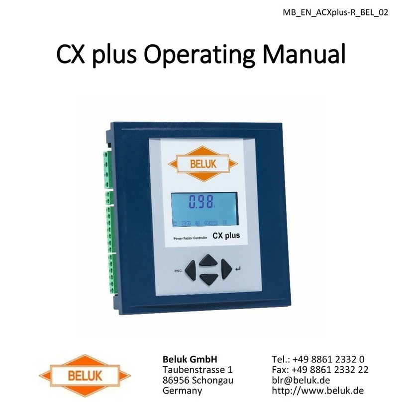
Beluk CX plus User manual

Beluk
Beluk BLR-CM Modbus Guide
Beluk
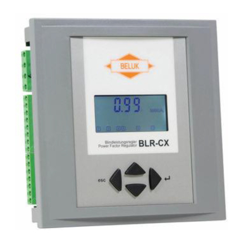
Beluk BLR-CX User manual

Beluk
Beluk BLR-CM Training manual
Beluk
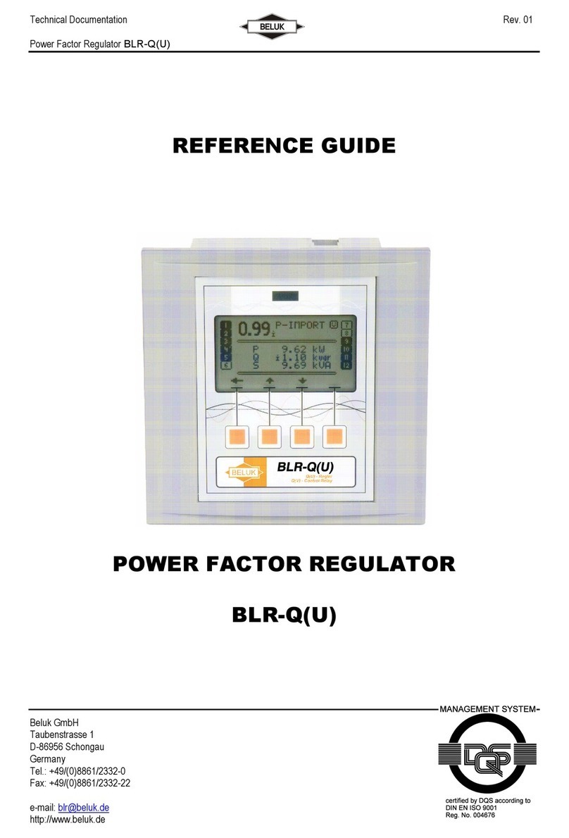
Beluk BLR-Q(U)06/12R User manual
Beluk
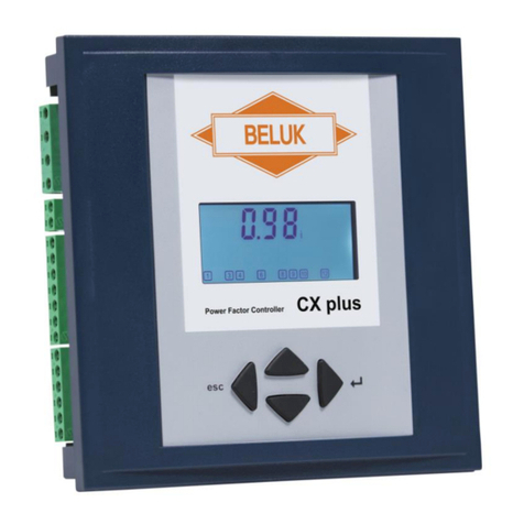
Beluk CX plus User manual
Beluk
Beluk CX plus User manual
Beluk
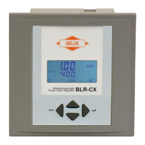
Beluk BLR-CX-R User manual
Beluk
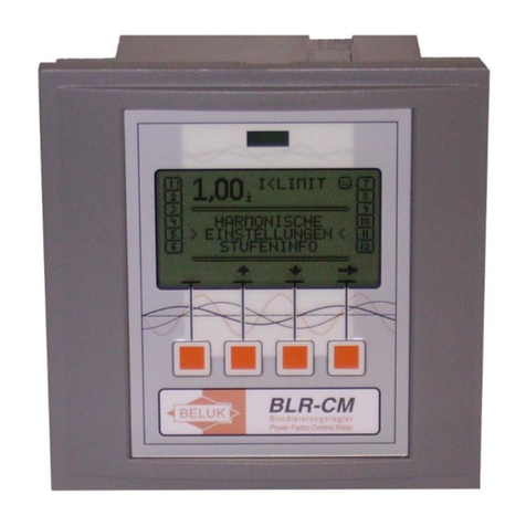
Beluk BLR-CM 3 phase User manual

Beluk
Beluk BLR-CX Installation and operation manual
Popular Controllers manuals by other brands
Flowserve
Flowserve Valtek VL-C User instructions
dixell
dixell XC660D Installing and operating instructions
Oxygen
Oxygen Medea Translation from original instructions
GFA
GFA TS 981 installation instructions
Vector
Vector TLC3-FCR-2T Engineering manual
Auber Instruments
Auber Instruments SYL-3615 instruction manual
