Benassi BL 6000 User manual

SpA
INSTRUCTION MANUAL
TILLER
BL6000
19/04/2011

SpABL6000
2
INDEX
INTRODUCTION…………………………………………………………………....2
SAFETYRULES............................................................................2
KEYTOMACHINEPARTS...........................................................3
IDENTIFICATIONSANDTECHNICALSPECIFICATIONS ...............3
CEMARK .................................................................................3
TILLINGUNITS ........................................................................3
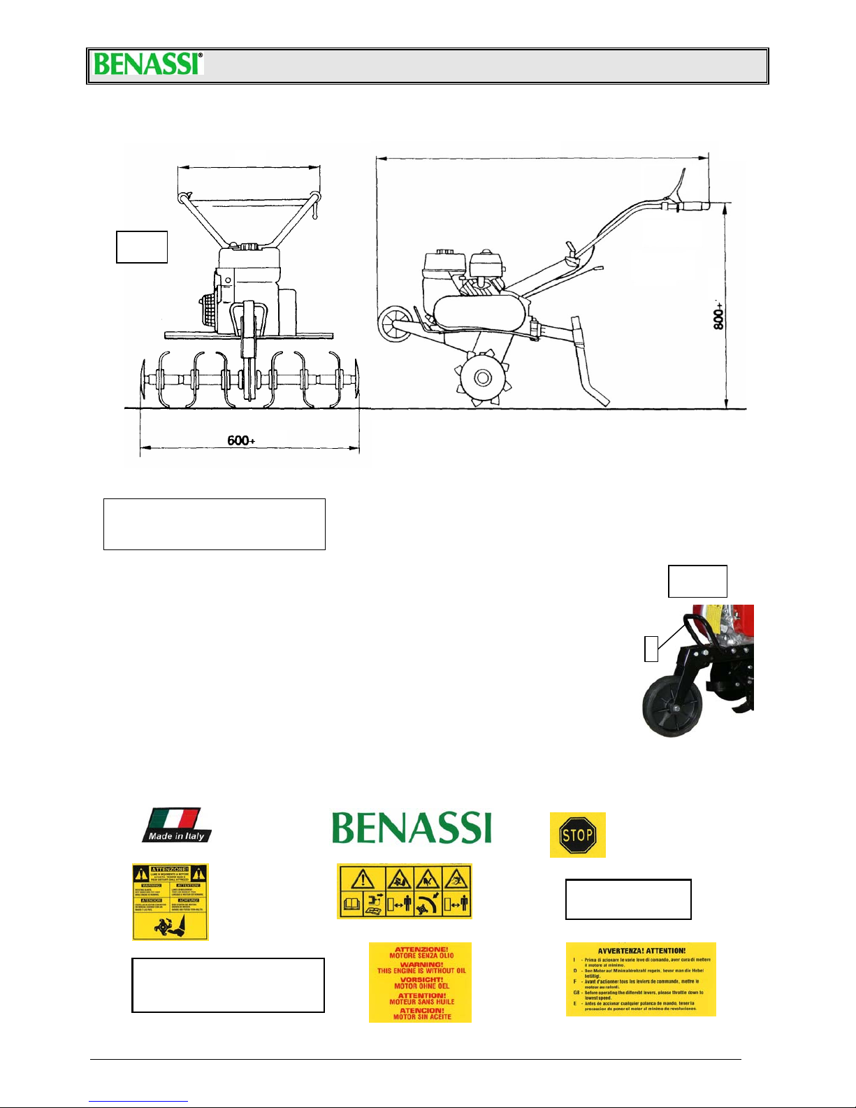
DIMENSIONS ..........................................................................4
PACKINGANDTRANSPORT…………………………………………………...4
STICKERSFORINSTRUCTIONANDSAFETY ...............................4
STARTINGANDSTOPPING..................................................... 5
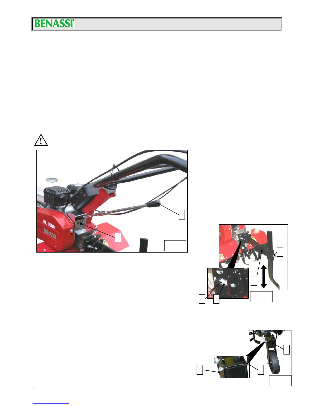
USEANDADJUSTMENT......................................................... 6
SPURADJUSTMENT ............................................................... 6
TRANSFERWHEELADJUSTMENT........................................... 6
SERVICING................................................................................. 7
CLUTCHBELT ......................................................................... 7
WARRANTY............................................................................... 8
INTRODUCTION
•Dearuser,wethankyouforpreferringaBENASSIproduct.
•Weareconfidentthatthetopperformanceandtheeasyuseofourmachinewillsatisfyyou.
•Thismachineistheresultofalongexperienceworkingatthetopqualitystandardandusingfirstqualitymaterial.
•Carefullyusingandservicingthismachine,youwillcertainlygetsatisfactoryperformancesforalongtime.
•Pleasereadverycarefullythisbookletbeforeusingyourtiller.
•Payspecialattentiontotheinstructionsmarkedoutbythefollowingsign:
ATTENTION
•Failuretocomplywiththeseinstructionscancausefatalinjury(TRANSLATEDFROMTHEORIGINALMANUAL).
SAFETYRULES
WARNING:Please,readverycarefullythisbookletbeforeusingyourmachine.Carefullyusingand
servicingthismachine,youwillcertainlygetsatisfactoryperformancesforalongtime.
FailuretocomplywiththeseinstructionsmayCAUSEfatalinjuryTOTHEOPERATORORDAMAGETO
THEMACHINE.
•Pleasereadcarefullytheoperationandmaintenancemanualsuppliedwiththemachine.
•Theuseofthemachineisforbiddentopersonsyoungerthan16years.
•Theoperatorisresponsibleofanypossibledamageandheshouldalwaysdrivethemachine
carefullyandsafely.
•Anypersonunfamiliarwiththemachinewhohasneveruseditisobligedtoreadfirstthe
instructionmanual.
•Beforecarryingthemachinealwaysemptythefueltank.
•Beforeleavingthemachinebesurethatitisfullystopped.
•Neverusethemachinebarefootorwearingsandals,alwayswearheavyshoesandlongtrousers.
Alwaysinspecttheareawhereyouwanttoworktakingoffstones,branches,wiresandanyother
thingwhichcouldbedangerous.
•Beforestartworking,makesurethataradiusofminimum5mt.iscompletelyfree.
•Cleananypossibleleakageoffuel.
•Alwaysfillupthetankwhentheengineisoffinanopenspacefarfromfiresoranyheatingsource
anddon’tsmokeduringthisoperation.
•Beforestartingthemachinemakesurethatyoucanquicklystoptheengineandthatyouare
familiarwiththecontrollevers.
•Neverallowtheenginetoruninenclosedspaceswherethehighlytoxiccarbonmonoxidecould
notevacuate.
•Neverstartorusethemachineifnotcompletelyassembledandequippedwiththesafetydevices.Neverworkwithoutthetiller
protectionguards.
•Neverfixorcleanthetillerbladesoranyothertoolswhentheengineisrunning.
•Attention!Don’tworkonslopesexceeding30%.
•Foraccidentscausedbyfailureoftheseruleswewillnotbeheldliable.

SpABL6000
3
KEYTOMACHINEPARTS
1‐Transportwheel
2‐Engineoilcap
3‐Tillers
4‐Tillerprotection
5‐Brakingspur
6‐Beltcover
7‐Gearlever
8‐Clutchlever
9‐Throttlelever
10‐Handlebaradjustment
11‐Fueltankcap
12‐Handle
13‐Recoilstarter
14‐Chokelever
15‐Aircleaner
IDENTIFICATIONANDTECHNICALSPECIFICATIONS
ATTENTION:FORTHEENGINETECHNICALSPECIFICATIONS,SEETHEENCLOSEDOWNER’SMANUALOFTHEENGINE.
•AcousticpowerlevelLwA=from92dB(A)to105dB(A)
•Noiselevelatoperator’sear:LpA=from81dB(A)to90dB
(A)
•Testcondition:1,6mtatthecentreofthehandlebar
•HandlebarvibrationaccordingtoISO1033:valuefrom4,76
m/sec²to7,00m/sec²
CHARACTERISTICSOFALLTHEENGINESFITTED:
•Exhaustguard
•Recoilstarter
•ENGINELUBRICATION:seetheowner’smanualoftheengine
•Engineoilquantity:seetheowner’smanualoftheengine
•Enginefuel:unleadedpetrol
•Safetydeviceforbothforwardandbackwardgearstopping
thetiller.
•Thegearhasgottwoforwardspeedsandonereverse,abelt
joinsthetransmissiontotheengineandanoiledchainto
thetiller.
SPECIFICATIONSWITHENGINERUNNINGAT3200RPM
Iforward=82rpm
IIforward=113rpm
Reverse =61rpm
•Speedgearinoilbath
•Beltclutchwithtightener
•Tillerwithhexagonalshaftandreinforcedblades
•Guidancehandlebarscanbeadjustedinmanypositions(ver‐
ticalandsideadjustment).
•Thetilleris80cmwide.
•Thespurisadjustable
APPLICABLEACCESSORIES
•Ridgerwithattachment
•Thinironwheels(Ø320)aresuitablewhenusingtheridger
CEMARK
Toidentifythemachine(serialnumber,engine,weight,power)
havealookatthenumberplateputonthemachineasin(Pic‐
ture1Ref.“A”).
TILLINGUNITS:
Thebladesareadjustableandprovidedwithaprotectionmudguard.Inpicturenumber2youcanseethepossibleworkingwidth:60–
80cmwiththeextensionsandthesideplatesfitted.
A
Fig.1
Fig.2
800
Ø315
1
23
4
6
5
7
89
10
11
12
HONDAKIPOR
1313 14
14
15
15

SpABL6000
4
Fig.4
A
DIMENSIONS
Thedimensionsofthetillerareshowninpicture3.
PACKINGANDTRANSPORT
◊Length:80cm.
◊Width:50cm.
◊Height:70cm.
•Takethemachineoutofthecartonbox.
•Fitthetwotillingunitstothemainshaftusingthedeliveredpinsalreadyassembledonthetillingunits.
•Fitthearmwithspurinitsplaceusingthedeliveredpin.
•Fixthehandlebartothehandlebarsupportusingthepartsalreadyassembledonthehandlebarsupport
itself.
•Thesmallwheelholderisfittedtotheframebymeansofascrewnutandasplintpin.
•Fitthetwoguard‐extensionstothemaintillerprotectionsfittedonthebodyofthemachineusingthe
properscrewsandnuts.Theprotectionguardsshouldreachawidthof60cmaccordingtotheCE
requirements.
•Duringthetransportthehandlecanbeleftunassembledbymeansofthethreadedbushthatfixittothe
handlebarsupport.Thetillerisequippedwithafronthandle(seePict.4Ref.”A”)inordertobeableto
liftandtotransportthemachineeasily.
STICKERSFORINSTRUCTIONANDSAFETY
Pleasefindherebelowthestickersputonthemachine.Itisveryimportantthattheyarealwaysclearlylegibletopreventanyaccident.
Incasethestickersaredamageditisabsolutelynecessarytoreplacethembyorderingtheoriginalspareparts.
R· 2· 0· 1
BL 6000
1)2)
4)6)
7)8) 9)
3)
5)
6001660
1150
Fig.3
800

SpABL6000
5
STARTINGANDSTOPPING
Wheneveryouarestartingtheengineofthemachine,followtheseinstructionsverycarefully:
•Checktheengineoillevel:ABRANDNEWMACHINEISDELIVEREDWITHOUTOILINTHEENGINE,THEREFOREYOUSHOULDFILLIT
UPTOTHELEVELONTHEDIPSTICKOFTHEOILCUP.
•PleasereadcarefullyonthebooklettheENGINEUSEANDMAINTENANCEconcerningthe“operationsbeforestarting”.
•Starttheengineonlyinopenspaces.
CLUTCHLEVERPROVIDEDWITHSAFETYDEVICE(seepicture6b)
•Lever(“A”)pulled:togettheleverworkingreleasethesafetydevice(“B”),nowtheclutchisengaged(thetillermovesforwardor
backwardsdependingontheengagedgear)
•Lever(“B”)released:clutchleverdisengaged(thetillerstops).
1. Pullthechokelever(Pict.5Ref.“A”).
2. Turnthethrottlelevertothe“MAX”position(Pict.6aRef.“A”).Theswitch(Ref.“A”Pict.6a)mustbe“ON”.
3. Theclutchlever(Pict.6bPosition“A”)mustbedisengaged.
4. Pullthestartingropebythehandle(Pict.5Ref.“B”),firstlysmoothlyandthenstrongly:whenyoufeelsomeresistancedon’tlea‐
vethehandlebuthelptherecoilingoftheropewithyourhand.
5. Whentheenginerunsmovethechokelevertotheinitialpositionandthethrottleleverinthemid‐position(Pict.6aRef.“B”).
6. Tostoptheenginemovetheswitchtothe“OFF”position(Fig.6aRef.”A”).
Pict.6a
A
B
Pict.6b
AB
KIPOR
A
B
HONDA
Pict.5
A
B
A
Pict.6
B
C

SpABL6000
6
Pict.8
A
B
D C
AB
C
Pict.9
USEANDADJUSTMENT
•Thetillerisequippedwithamechanicaltransmissionthatallowstwoforwardspeedsandonereverse.
•Whenthemachineisstandstilltomoveforwardsimplyengagethegearlever(Pict.7Ref.“A”)inthefirstorinthesecondspeed
(Pict.7Ref.“B”)andthenpressdowncompletelythelever(Pict.6bRef.“A”)tostartthemovement.
•Whenthemachineisstandstilltomovebackwardsengagethegearlever(Pict.7Ref.“A”)intheposition“R”(Pict.7Ref.“B”)and
thenpressdowncompletelythelever(Pict.6bRef.“A”)tostartthemovement.
•Theclutchcablemustbeadjustedinawaythatallowsthebelttobeputundertensionwhentheleverissituatedatabout1cm
fromtheknob.Tothispurposeyouhavetoregulatetheregisterofthecablenexttothelever(Ref.“B”Pict.6).
•Whenthelever(Pict.6bRef.“A”)isreleasedthemachinestopsimmediatelywhiletheengineisrunning.
•Thehandlebarcanbeadjustedbyunscrewingtheblockinglever(Pict.6Ref.“C”).Adjustthehandlebarinthedesiredpositionand
thenlockitagain.
•Thetilleris80cmwide,itiscomposedby3knives+protectionplateonbothsides.Itcanbereducedto60cmbyremovingone
bladefromeachsides(seepicture2).
•Thesharpsideofthebladesmustbeturnedtowardsthefrontsideofthemachine.
•Werecommendtousethetillerwiththesideplatesbecausetheyimprovethestabilityofthemachinewhileworking.
•Themachinecanfitanadjustableridgerwhichisanoptionalaccessorydeliveredcompletewithitsownsupportwhichshouldbe
fittedonthehandlebarholderreplacingthestandardspurandusingthesamebolt.
CAUTION:ITISADVICEDNOTTOKEEPTHEMOTORRUNNINGWHENTHEMACHINEISNOTBEINGUSEDFOR
ITSSPECIFICALPURPOSE.
SPURADJUSTMENT
Togetanoptimaltillingworkandarightadvancementofthetilleradjustthespurasshownin
picture8,thisadjustmenthastobedoneonbothsidesofthemachine:
−Adjustmentforhardsoils:loosennutandscrew(A)andliftthespurastoshiftbackthe
weightofthemachine.
−Adjustmentforsoftsoils:loosennutandscrew(A)andlowerthespurastomovethe
weightofthemachinetowardsthebladesaxle.
Toenablethetillertomoveslightlysidewaysduringthetillingwork,thespurholderarm
(B)canbeadjustedhorizontallyasfollows:
a. loosenthenut(C)andadjustthescrew(D)asdesired,thentightenthenutagain.Bytighteningthescrew(D)thespurcanmovesi‐
deways.
b. carryoutthesameadjustmentalsoontheothersideofthearm.
TRANSFERWHEELADJUSTMENT
Totransferthemachinethesmalltransferwheelhastobelowered(seepicture9).Beforeworkingremovethesplintpin
(B)andtheclampingpin(A),liftupthesmalltransferwheel(C)andinserttheclampingpin(A)againin
thelowerhole.Theclampingpinalwayshastobelockedinthedesiredpositionbymeansofthe
splintpin(B).
A
B
Pict.7

SpABL6000
7
Pict.10
A
B
SERVICING
Fortheusualengineservicing(oil,filter,sparkplugandadjustments)readtheenginemanual
deliveredwiththemachine.
•Itisnecessarytocheckperiodicallytheoillevelinthegearboxbyatleastevery50workinghours.If
necessaryaddMPSSAE80/90oil.
•Theoilhastobechangedevery200workinghours.Unscrewthecap(Ref.“B”Pict.10),drainoutall
theoillettingthecap(Ref.“A”Pict.10)open.Thenputbackthecap(Ref.“B”Pict.19)andtopup
withoil(about1,3litres).
•Theframehaswaterproofballbearings.Thetransmissionintheframeisengagedbytwonormal
grease‐lubricatedchains.
•Allthejoints,thecablesandthetightenersupportboltshouldbeoiledfromtimetotime.
•Keepthemachineandthebladesclean.Checkperiodically,atleastonceayear,thatallthescrews
andnutsarewelltied,especiallythescrewsofthetiller(alwayswearprotectiongloveswhile
workingonthetiller).
•Incaseofbreakingorwearofthebelt,youcanreplaceitaftertakingoffthesideprotectioncover
byunscrewing2knobsfixingthesideprotectioncover(Pict.11Ref.“A”).
•Takeoffthebeltfromthepulleysandinstallthenewbelt.Afterreplacingthebelt,adjustittothe
correcttensionfollowingtheinstructionsinthechapter“CLUTCHBELT”,thenreassemble
thecoveragain.
Foranytechnicalrepairespeciallyduringtheguaranteeperiod,itissuggestedtoapplytothe
specialisedworkshopsofourdealers.
CLUTCHBELT
Clutchbeltadjustment (seepicture12)
Removethecoverbyunscrewingbothfasteningscrews,asecondoperatorwillpulltheclutchlever(A).Verifythatthebelt(C)hasgot
amaxdistanceof2,7cmandifitdoesn’thappenproceedasfollows:
a. adjustthebelttensionbyregulatingtheclutchlever(A)throughtheadjustingscrew(B)onthelefthandlebar;
b. ifthebeltdistance(C)isstilloutofthementionedtolerance,loosenthefourbolts(D)clampingtheengineandshifttheengine(E)
forwardstillyougettherightvalues.
Clutchbeltreplacement(seepicture12)
a. loosentheadjustingscrew(B)onthelefthandlebarandextractthebeltfromthepulleys.
b. Installthenewbeltonthepulleysverifyingthatthemax.distanceisabout2,7cmandthattheclutchleverdoesn’thaveanyclea‐
ranceotherwisecarryouttheadjustmentdescribedbefore.
Pict.11
A
A
Pict.12
A
2,7cm
E
D
B
C

SpABL6000
8
WARRANTY
Ourmachinesandaccessoriesareguaranteedfor2yearsexcludingelectricandrubberparts.
Allthedefectivepartswillbereplacedfreeofchargeexcludingcostoflabourandtransportfeeswhichwouldbeatcustomer’scharge.
Foranyproblemregardingtheengineoranyotherpartnotofourproductionpleaserefertotheguaranteeconditionsstatedbythe
manufacturerandapplytotheirassistancecentres.
Foranykindofproblemorrepairpleaseapplytothedealerwhereyouboughtthemachine.
S.p.A.
VIALAMPEDUSA1
40017S.MATTEODELLADECIMA(BO)‐ITALY
TEL.+39/051/820511TELEFAX+39/051/6826164
e‐mail:[email protected]web:www.benassi.eu
Table of contents
Other Benassi Tiller manuals

Benassi
Benassi MC 3300 User manual

Benassi
Benassi BL 300 User guide

Benassi
Benassi MC 2300 REVERSO Instructions for use

Benassi
Benassi BL355 User manual

Benassi
Benassi BL30 User guide

Benassi
Benassi BL 105 User guide

Benassi
Benassi BL 10 Series Manual

Benassi
Benassi MC 2300 REVERSO Instructions for use

Benassi
Benassi BL200 User manual

Benassi
Benassi BL304 Quick guide