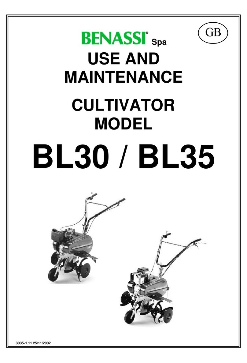
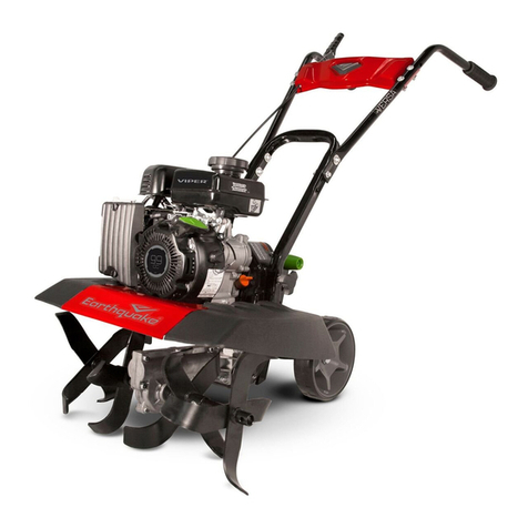
Benassi BL301H User manual


BENASSI srl Via Lampedusa, 1 – 40017 S.M. Decima (BO – Italy – Tel. +39 051 820 511 – www.benassi.eu – benassi@benassispa.it
A g r i c o l t u r a e G i a r d i n a g g i o
8607405 BL301 L
8606935 BL301 H
BL 301
Motore
Engine
Lifan LFE168
Honda G
X
16
0
Larghezza lavoro
Working width
Velocit
Speed
60 cm
1 avanti
1 forward
Peso
Weight 60 kg
Leva con blocco
di sicurezza
Lever with safety
Stegola regolabile
Handlebars adjustable
Trasmissione a Cinghia
V belt transmission
Supporto stegola speciale
Special Handlebar Support
Sperone registrabile
Adjustable spur
Carter trasmissione
catena imbullonato
Bolted frame
Fresa con mozzo esagonale E23,
zappe imbullonate e Dischi
Tool with Exagonal pipe , Protection discs and
bolted knives
Ruota di trasferimento
Transport wheel
ACCESSORI
ACCESSOIRES
Assolcatore
Ridger
Rulli tagliaerba
Grass cutting cages
Ruote in ferro
Iron wheels
Manettino Stop Motore
Engine stop switch

BL301
2
1
13
10
12

BL301
3
RIF.
PARTI DELLA MACCHINA PARTS OF THE MACHINE
1 Ruotino di trasferimento Transport wheel
2 Fresa Tiller
3 Carter fresa Tiller protection
4 Sperone Braking spur
5 Carter protezione cinghi Belt cover
6 Leva marcia avanti Clutch lever forward drive
7 Manettino acceleratore Throttle lever
8 Registro manubrio Handlebar adjustments
10 Filtro aria Air filter
11 Tappo entrata carburante Fuel tank cap
12 Leva starter Choke lever
13 Avviamento motore Recoil start
13 Tappo entrata olio Oil cap

BL301
4
2
3
6
7
8a/ 8b

BL301
5
n.9
n.11
n.12
n.13

BL301
6
n.15
n.18
n.19
n.20

BL301
7
INDEX
1. INTRODUCTION
2. TECHNICAL DETAILS
3. INSTRUCTION FOR ASSEMBLY
4. SECURITY TERMS
5. STARTING AND STOPPING
6. USE AND ADJUSTMENT
7. MAINTENANCE
8. EC LABEL
9. WARRANTY
10. EC DECLARATION OF CONFORMITY
1.
INTRODUCTION
Dear user, thank you for preferring , The top performance and the easy use of our machine should give
you any satisfaction.
This machine is the result of a long experience working at the top quality standard and using first quality
material.
Carefully using and servicing this machine, you will certainly get satisfactory performances for a long time.
Please read very carefully this booklet before using your machine.
The greater attention you give to our technical instructions the more reliable your machine will be. Pay
special attention to the instructions marked out by the following sign
DANGER!
Failure to comply with these instructions may result insidious or even cause fatal injury.
TRANSLATED FROM THE ORIGINAL)

BL301
8
2.
TECHNICAL DETAILS
Model : BL301H - BL301L
Engine fuel unleaded petrol
Exhaust guard
Recoil starter
Dry or oil bath air filter ( See engine type)
Safety device for stopping the tiller.
Single belt transmission
Greased chain
Handlebar: adjustable in different positions (height and side)
Tiller large 60 cm
Gear-box screwed (Pict. 2).
Spur it can be adjustable (Pict 3 Ref. “B”).
Max working slope: 30%
Packing (carton box) 80 x 60 x 70 cm ( Width x length x height)
Acoustic power level LwA = 94 dB (A)
Acoustic pressure to the operator’s ear: LpA = 80 dB (A)
Vibration to handlebar with weighting UNI EN 1033 value: 3 – 5 m/sec²
FOR THE ENGINE FEATURES SEE THE ENGINE INSTRUCTION BOOKLET DELIVERED WITH THE MACHINE.
All the identification references (code number, engine, weight, power)
are printed on the number plate on the machine (Pict. 6 Ref. “D”).

BL301
9
3.
INSTRUCTIONS FOR ASSEM LY
•Take the machine out of the carton box.
•Fit the two tillers to the main shaft using the delivered screws and nuts.
•Fit the rear spur in its place using the delivered bolt and both pins which are on the spur holder.
•Fit the handlebar on the support:
- The model with the full-side adjustment (rack, wheel system) is fitted with the parts already mounted on
the handlebar holder.
•The front wheel holder is fitted to the frame by means of two pins with cotter and spring. The small wheel
has to be fitted on the holder through screw and nut. To put the small wheel in the requested position pull
outwards till the pin is completely inside the buttonhole (see picture n.7).
•Fit the two guard-extensions to the main tiller protections fitted on the body of the machine using the proper
screws and nuts.
•To make the transport easier it is possible to keep the handlebar disassembled, by means of the two
screws in one version or by means of the thread bushing in the other one, that fix it to the handlebar holder.

BL301
10
4.
SECURITY TERMS
WARNING:
Please read very carefully this booklet before using your cultivator;
Carefully using and servicing this machine, you will certainly get satisfactory performances for a long time..
FAILURE TO COMPLY WITH THESE INSTRUCTIONS MAY RESULT INSIDIOUS OR EVEN FATAL INJURY.
•The use of the machine is forbidden to persons younger than 16 years.
•The operator is responsible of any possible damage and he should always drive the machine carefully and
safety.
•Before carrying the machine always empty the fuel tank.
•Before leaving the machine be sure that it is fully stopped.
•Never use the machine without heavy shoes and long transfers. Always inspect the area where you want to
work taking off stones, branches, cables and any other thing which can be dangerous.
•Before start working, make sure that a radius of minimum 5 mt. is completely free.
•Clean any possible leakage of fuel.
•Fill up when the engine is off and not hot, always in an open space far from fires or any heating source and
refrain from smoking during this operation.
•Before starting the machine make sure that you can quickly stop the engine and that you are familiar with
the control levers.
•Never allow the engine to run in enclosed spaces where the highly toxic carbon monoxide could not
evacuate.
•Never start or use the machine not completely assembled especially concerning the safety devices and the
tiller protection guards which should always be completely assembled with all its extensions.
•Never fix or clean the tiller blades or any other tools when the engine is running.
Attention ! Don’t’ not exceed the maximum working slope.
•We are not responsible for accidents due to the wrong use of the machine neglecting the above basic
instructions.

BL301
11
5.
STARTING AND STOPPING
Starting the engine of the machine always follow these instructions very carefully:
Check the oil level in the engine :
THE NEW MACHINE IS DELIVERED WITHOUT OIL IN THE ENGINE, THEREFORE YOU SHOULD FILL
IT UP TO THE LEVEL ON THE DIP STICK OF THE OIL CUP.
Please check the engine USE AND MAINTENANCE concerning the “operations before staring”.
Start the engine only in open spaces.
1. Pull the choke lever on the engine.( where present is)
2. Turn the accelerator lever “F” to the “MAX” position (Pict. 8a and 8b). The switch (Ref. “K” Pict. 8b) must
be “ON”.
3. The clutch lever should be released in position “a” (Pict. 9).
4. Pull the starting rope by the handle “I” smoothly first than strongly: when you feel some resistance don’t
leave the handle but help the recoiling of the rope with your hand (Pict. 11).
5. When the engine runs move the choke lever to the initial position and the accelerator lever in the mid-
position (Pict. 8a and 8b Ref. “F”).
6. For stopping the engine move the accelerator lever “F” in “STOP” position (Pict. 8a) and the switch (Ref.
“K” Pict. 8b) must be “OFF”.

BL301
12
6.USE AND ADJUSTMENT
•You can start the rotation of the tiller unlocking the security device (Pict. 9 ) and pulling the clutch lever up to
position “b” (Pict. 9) the machine will immediately stop releasing the lever.
•In thIs model pulling the clutch lever in position “b” the correct space of the internal sides of the belt should
be of in the pict.12
•The best adjustment is when the lever of the forward or of the reverse gear in the position shown in picture
15, at a distance of about 10 mm from the knob, tightens the belt. Should this not be the case, please
proceed with the adjustments mentioned below.
•If the distance is different, you should adjust the tension of the idlers by means of the register screws “L”
and “M” of picture 16, so that the belts do not slide when the idlers are tightened. If this adjustment is still
not enough, you can move the engine on its guides after having turned out the clamping bolts: move the
engine towards the handlebar if you have to reduce the space.
In the type with full side and vertical adjustment (Pict. 18) you have to release the blocking lever “P” than
adjust the handlebar position as you prefer and lock it again.
•Adding other two sets of blades you can extend the tiller (Pict. 6). The blades of the tiller-knives should
always be directed ahead, towards the front of the machine.
•We recommend to use the tiller with the side plates because they improve the stability of the machine and
they protect from plants and any other obstacle.
•As optional accessory the machine can fit an adjustable ridger delivered complete with its own support
which should be fitted on the rear side of the machine, replacing the standard spur.

BL301
13
7.
MAINTENANCE
•For the normal maintenance check the booklet for the engine included.
•The chain for the final transmission is lubricated with standard grease.
Every year you should introduce some grease through the hole (Pict. 19) in the main body
•Keep the machine and the tillers clean and check that all the screws and nuts are well tied, especially the
screws of the tiller (always wear protection gloves working on the tiller).
•In case of breaking or wear you can replace the belt after taking off the side protection cover fixed to the
frame near the engine shaft by two screws .
•In order to remove the belt of the reverse gear, it is necessary to remove the small cover by unscrewing its
screw. Remove the belt from the pulleys, install the new belt end adjust it following the instructions
mentioned in the chapter USE AND ADJUSTMENT by checking the distance between both sides of the
belt, then replace the cover.
•The pin fixing the big pulley has also a safety purpose: in case heavy obstacle it will break avoiding
damages to other parts of the machine.
•The replacement of the pin is very easy: you have to insert the new pin in the hole using a hammer.
•For any technical repair especially during the guarantee period, it is recommendable to apply to the
specialized workshops of our dealers.
CAUTION
It is advised not to keep the motor running when the machine is not being used for its specific purpose

BL301
14
8. CE MARKING
The plate bearing the CE mark gives the main characteristics and information for the identification of the
machine.
Manufacturer’s details
Machine model
Serial number
Year of construction
Capacity in kW
Weight in kg
The above information must not be altered or modified in any way.
It is up to the user to keep the plate clean, legible and in good condition.
The position of the CE plate on the machine is shown in the picture 6.
9
WARRANTY
Our machines and accessories are guaranteed for 2 years excluding electric and rubber parts.
All the defective parts will be replaced free of charge excluding cost of labour and transport freight, which
would be at customer’s charge.
For any problem regarding the engine or any other part not of our production, please refer to the guarantee
conditions stated by the manufacturer and apply to their assistance centres.
For any kind of problem or repair please apply to the dealer where you bought the machine.

BL301
15
EC DECLARATION OF CONFORMITY
The undersigned of the company
BENASSI srl
VIA LAMPEDUSA, 1
40017 S.M. DECIMA (BO) ITALY
declares under its own responsibility that the new machine
Type: MOTOR HOE
Model: BL301
Serial Number from : > 22 1501 00000
Is conformity with the following Directives
2006/42/CE;
Applicable standard :
EN 709; EN ISO 12100
Person in charge of documentation: R. Tassinari
Roberto Tassinari
S.M.Decima, 01/06/2015 (Représentant Léga/)
Questa dichiarazione perde la sua validità se il prodotto viene modificato o trasformato senza accordo.

BL301
16
IT- LINGUA ORIGINALE
MANUALE D’USO E MANUTENZIONE
INDICE
1. PREMESSA
2. CARATTERISTICHE TECNICHE
3. IMBALLO E TRASPORTO
4. NORME DI SICUREZZA
5. AVVIAMENTO E ARRESTO DELLA MACCHINA
6. USO E REGOLAZIONI
7. MANUTENZIONE
8. MARCATURA CE
9. GARANZIA
10. DICHIARAZIONE CE DI CONFORMITA’
1. PREMESSA
RingraziandoVi della scelta effettuata, Le porgiamo il benvenuto tra i nostri numerosi clienti.
Siamo certi che le prestazioni e la semplicità di uso di questa macchina saranno di Vs. gradimento.
La lunga esperienza nel settore, l’impiego di materiali di alta qualità, la lavorazione accurata, assicurano una
perfetta efficienza della macchina che, se sarà usata correttamente con la necessaria manutenzione, Vi offrirà
prestazioni per molti anni.
Abbiamo perciò compilato questo libretto che le renderà familiare l’uso della macchina, la costruzione, le
caratteristiche di funzionamento e le applicazioni, facilitando anche la manutenzione.
Prestate particolare attenzione alle norme contenute nel presente libretto precedute dal seguente simbolo:
ATTENZIONE!
Questo simbolo indica che l’inosservanza di queste norme può portare a lesioni personali.

BL301
17
2. CARATTERISTICHE TECNICHE
Modello
Motore
BL301H – BL301L
a benzina 4 tempi
Protezione
marmitta
con griglia
Avviamento
con fune autoavvolgente
Filtro aria mot
ore
bagno olio
e
/o a
secco
(secondo versione)
Innesto della trasmissione
Leva con blocco
Frizione
a cinghia con tenditore
Marce 1 avanti
Trasmissione
a catena
Lu
brificazione ca
tena
con grasso
Stegole di guida Registrabili sia in altezza che trasversalmente.
Fresa
60 cm e dischi laterali.
Carter
-
telaio
imbullonato
(Fig.
2).
Sperone Registrabile (Fig. 3 Rif. “B”)
Ruotino
anteriore snodabile
Dimensioni imballo
80 X 45 X 70 cm (LARGHEZZA x PROFONDITA’ x ALTEZZA)
Pendenza max di lavoro
30%
Livello di potenza acustica LwA
9
4 dB (A)
Pressione acustica all’orecchio
dell’operatore : LpA
80 dB (A)
Vibrazion
e
alle stegole UNI EN 1033
3
–
5
m/s²
Per dettagli sul motore si veda il manuale uso e manutenzione del costruttore.

BL301
18
3. IM ALLO E TRASPORTO
•Togliere la Motozappatrice dall’ imballo.
•Fissare le frese all’albero porta frese, tramite i bulloni che sono premontati sulla fresa.
•Fissare lo sperone nella sua apposita sede tramite il perno e le spine già montate sull’ attacco sperone.
•Fissare le stegole al supporto manubrio.
Nella versione registrabile in tre posizioni , fissare tramite le due viti con pomello e dado.
Nella versione registrabile con sistema a dente di lupo, fissare la stegola con la bulloneria predisposta.
•Il supporto ruotino è fissato al telaio tramite perni, copiglie e molla. Il ruotino va montato ( se necessario)
sul supporto con vite e dado.
Per inserire il ruotino nella posizione desiderata, tirare verso l’esterno e lasciare fino a innesto completo del
perno nell’asola. (Vedi Fig. n°7)
•Fissare le due prolunghe laterali al carter fresa centrale tramite le viti in dotazione.
•Per comodità’ di trasporto è possibile tenere la stegola smontata.
Utilizzare le viti o la boccola filettata a seconda della versione.

BL301
19
4.NORME DI SICUREZZA
IMPORTANTE:
Prima di utilizzare la macchina leggere attentamente questo manuale cercando di comprendere
bene il contenuto; Vi permetterà di ottenere dalla Vs. macchina le migliori prestazioni d’uso e di
durata.
VENIR MENO A CIO’ POTREBBE PORTARE DANNO ALLA PERSONA O ALLA MACCHINA.
•È vietato usare la macchina ai ragazzi.
•L’utilizzatore é responsabile dei danni poiché la macchina risponde ai suoi comandi.
•Qualsiasi persona che non conosca la macchina e che non l’abbia mai usata deve prima dell’uso, leggere
l’uso e manutenzione.
•In caso di trasporto vuotare il serbatoio della benzina.
•In caso di abbandono della macchina, fare in modo che non possa ripartire.
•Non lavorare mai a piedi nudi o calzando sandali. PreparateVi al lavoro indossando scarpe resistenti e
pantaloni lunghi; ispezionare prima la zona in cui si dovrà lavorare avendo cura di togliere le pietre, i
bastoni, eventuali fili metallici e qualsiasi altro oggetto estraneo.
•L’utilizzatore prima di mettere in moto deve avere un campo libero ( indicativamente nel raggio di 5 metri.)
•Asciugare le fuoriuscite di benzina
•Rifornire sempre il serbatoio a motore fermo. Il rifornimento e/o il travaso del carburante deve essere
sempre effettuato all’esterno, lontano dal fuoco o da sorgenti di calore. Non fumare durante questa
operazione.
•Prima di iniziare ad usare la motozappa é necessario imparare a spegnere rapidamente il motore,
familiarizzare con i comandi ed imparare ad utilizzare correttamente la macchina.
•Non fare funzionare il motore dove si possono accumulare i gas di scarico contenenti ossido di carbonio.
•Non utilizzare mai la motozappa incompleta o sprovvisto di relativo dispositivo di protezione. Non
effettuare mai operazioni di zappatura con la macchina priva del cofano protezione posteriore.
•Non montare/smontare, né pulire la fresa o eventuali attrezzi a motore acceso.
ATTENZIONE: Non usare la macchina in pendenze superiori a quanto previsto.
•Per incidenti causati da inosservanza di queste regole non ci riteniamo assolutamente responsabili.
This manual suits for next models
4
Table of contents
Languages:
Other Benassi Tiller manuals
Benassi
Benassi BL 45 Manual

Benassi
Benassi BL 4000 User manual
Benassi
Benassi BL200 User manual
Benassi
Benassi BL 10 Manual
Benassi
Benassi BL 300 User guide
Benassi
Benassi BL355 User manual

Benassi
Benassi MC 2300 REVERSO Instructions for use

Benassi
Benassi BL 6000 User manual
Benassi
Benassi BL 105 User guide
Benassi
Benassi MC 3300 User manual
