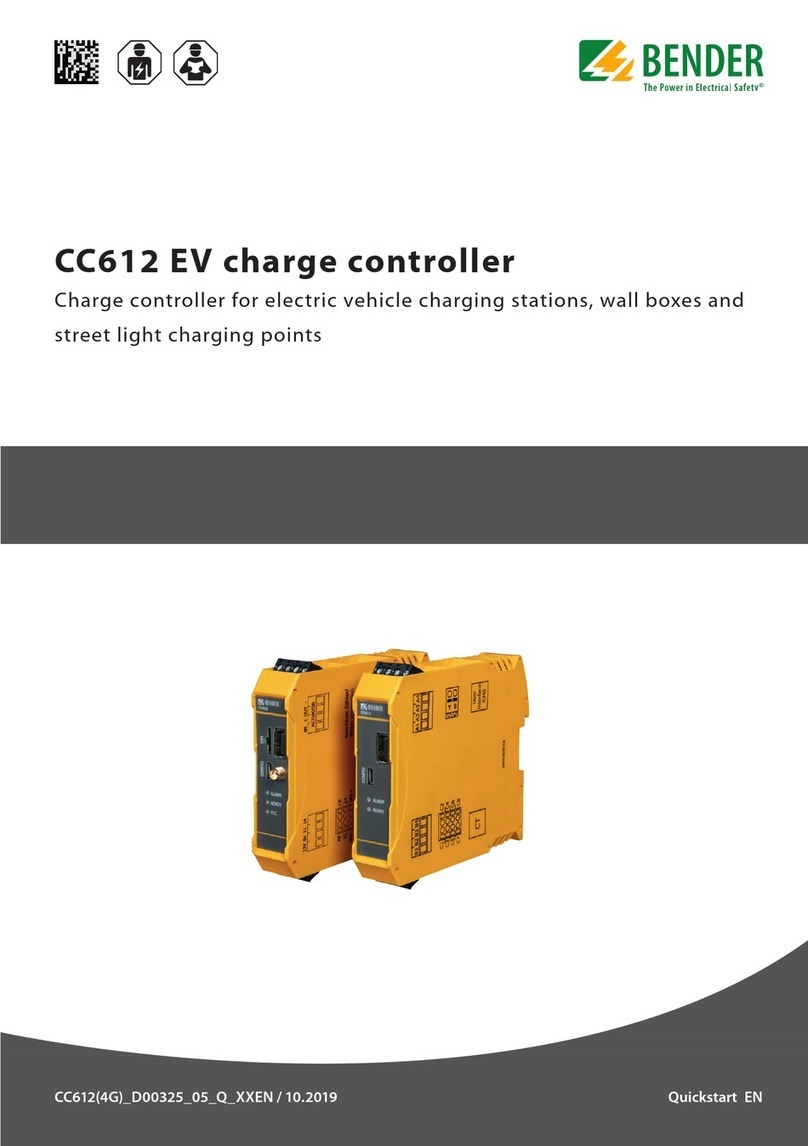
Bender CC612 User manual

EN
Manual
CC612(4G)_D00325_04_M_XXEN/03.2019
CC612 EV charge
controller
Charge controller for electric vehicle
charging stations, wall boxes and
street light charging points

Bender GmbH & Co. KG
Postbox 1161 • 35301 Grünberg • Germany
Londorfer Straße 65 • 35305 Grünberg • Germany
Tel.: +49 6401 807-0
Fax: +49 6401 807-259
E-Mail: [email protected]
Web: www.bender.de
© Bender GmbH & Co. KG
All rights reserved
Reprint only with permission
of the manufacturer
Subject to change
Customer service
Service-Hotline: 0700-BenderHelp (Phone and Fax)
Carl-Benz-Straße 8 • 35305 Grünberg • Germany
Tel.:+49 6401 807-760
Fax:+49 6401 807-629
E-Mail:[email protected]

3
CC612(4G)_D00325_04_M_XXEN/03.2019
1. Important information .................................................................... 5
1.1 How to use this manual . . . . . . . . . . . . . . . . . . . . . . . . . . . . . . . . . . . . . . . . . . . . . 5
1.2 Technical support: Service and support . . . . . . . . . . . . . . . . . . . . . . . . . . . . . 5
1.2.1 First level support . . . . . . . . . . . . . . . . . . . . . . . . . . . . . . . . . . . . . . . . . . . . . . 5
1.2.2 Repair service . . . . . . . . . . . . . . . . . . . . . . . . . . . . . . . . . . . . . . . . . . . . . . . . . . 5
1.2.3 Field service . . . . . . . . . . . . . . . . . . . . . . . . . . . . . . . . . . . . . . . . . . . . . . . . . . . . 6
1.3 Training courses . . . . . . . . . . . . . . . . . . . . . . . . . . . . . . . . . . . . . . . . . . . . . . . . . . . . 6
1.4 Delivery conditions . . . . . . . . . . . . . . . . . . . . . . . . . . . . . . . . . . . . . . . . . . . . . . . . . 6
1.5 Inspection, transport and storage . . . . . . . . . . . . . . . . . . . . . . . . . . . . . . . . . . . 6
1.6 Warranty and liability . . . . . . . . . . . . . . . . . . . . . . . . . . . . . . . . . . . . . . . . . . . . . . . 6
1.7 Disposal. . . . . . . . . . . . . . . . . . . . . . . . . . . . . . . . . . . . . . . . . . . . . . . . . . . . . . . . . . . . 6
2. Safety information ........................................................................... 7
2.1 General safety instructions. . . . . . . . . . . . . . . . . . . . . . . . . . . . . . . . . . . . . . . . . . 7
2.2 Work activities on electrical installations. . . . . . . . . . . . . . . . . . . . . . . . . . . . . 7
2.3 Dangers dealing with the charge controller. . . . . . . . . . . . . . . . . . . . . . . . . . 7
2.4 Precautions . . . . . . . . . . . . . . . . . . . . . . . . . . . . . . . . . . . . . . . . . . . . . . . . . . . . . . . . 7
2.5 Intended use . . . . . . . . . . . . . . . . . . . . . . . . . . . . . . . . . . . . . . . . . . . . . . . . . . . . . . . 7
3. Function ............................................................................................. 8
3.1 Product features. . . . . . . . . . . . . . . . . . . . . . . . . . . . . . . . . . . . . . . . . . . . . . . . . . . . 8
3.2 Product description . . . . . . . . . . . . . . . . . . . . . . . . . . . . . . . . . . . . . . . . . . . . . . . . 8
3.2.1 Product variant overview . . . . . . . . . . . . . . . . . . . . . . . . . . . . . . . . . . . . . . . 9
3.3 Functional description . . . . . . . . . . . . . . . . . . . . . . . . . . . . . . . . . . . . . . . . . . . . . . 9
3.3.1 General functions . . . . . . . . . . . . . . . . . . . . . . . . . . . . . . . . . . . . . . . . . . . . . . 9
3.3.2 Way of connecting with Type 2 socket . . . . . . . . . . . . . . . . . . . . . . . . . 11
3.3.3 Charging system with a type 2 socket and an intermediate relay 12
4. Device overview .............................................................................. 14
4.1 Dimensions . . . . . . . . . . . . . . . . . . . . . . . . . . . . . . . . . . . . . . . . . . . . . . . . . . . . . . . 14
4.2 DIN rail mounting . . . . . . . . . . . . . . . . . . . . . . . . . . . . . . . . . . . . . . . . . . . . . . . . . 14
5. Connection .......................................................................................15
5.1 Connection conditions. . . . . . . . . . . . . . . . . . . . . . . . . . . . . . . . . . . . . . . . . . . . .15
5.2 Connectivity . . . . . . . . . . . . . . . . . . . . . . . . . . . . . . . . . . . . . . . . . . . . . . . . . . . . . . .16
5.2.1 Master/Slave connections . . . . . . . . . . . . . . . . . . . . . . . . . . . . . . . . . . . . .17
5.2.1.1 USB configuration interface (CONFIG) . . . . . . . . . . . . . . . . . . . . . . .17
5.2.1.2 USB interface for Ethernet/WLAN adapter . . . . . . . . . . . . . . . . . . .17
5.2.1.3 Front panel LEDs (ALARM, READY, PLC) . . . . . . . . . . . . . . . . . . . . .17
5.2.1.4 12 V power supply . . . . . . . . . . . . . . . . . . . . . . . . . . . . . . . . . . . . . . . . .17
5.2.1.5 Contactor connection . . . . . . . . . . . . . . . . . . . . . . . . . . . . . . . . . . . . . .17
5.2.1.6 Control Pilot (CP) and Proximity Pilot (PP) connections . . . . . .18
5.2.1.7 I/O extension . . . . . . . . . . . . . . . . . . . . . . . . . . . . . . . . . . . . . . . . . . . . . . .18
5.2.1.8 RDC-MD (Residual Direct Current Monitoring Device) . . . . . . . .18
5.2.1.9 Plug lock connection . . . . . . . . . . . . . . . . . . . . . . . . . . . . . . . . . . . . . . .18
5.2.1.10 Connection to lock release modules . . . . . . . . . . . . . . . . . . . . . . . .19
5.2.1.11 Connectivity to eHZ or Modbus meters and (optionally) meters with
an S0 interface 24
5.2.1.12 User interface connection . . . . . . . . . . . . . . . . . . . . . . . . . . . . . . . . . .24
5.2.2 Master device features . . . . . . . . . . . . . . . . . . . . . . . . . . . . . . . . . . . . . . . . .25
5.2.2.1 SIM card and SIM card slot . . . . . . . . . . . . . . . . . . . . . . . . . . . . . . . . . .25
5.2.2.2 Antenna socket . . . . . . . . . . . . . . . . . . . . . . . . . . . . . . . . . . . . . . . . . . . .25
6. Configuration and testing .............................................................26
6.1 Configuration. . . . . . . . . . . . . . . . . . . . . . . . . . . . . . . . . . . . . . . . . . . . . . . . . . . . . .26
6.1.1 Local configuration and parameters . . . . . . . . . . . . . . . . . . . . . . . . . . . .26
6.1.1.1 Application of changed parameters . . . . . . . . . . . . . . . . . . . . . . . . .27
6.1.1.2 Automatic charge controller resets . . . . . . . . . . . . . . . . . . . . . . . . .27
6.1.2 Remote configuration and parameters . . . . . . . . . . . . . . . . . . . . . . . . .27
6.1.3 Factory settings . . . . . . . . . . . . . . . . . . . . . . . . . . . . . . . . . . . . . . . . . . . . . . .27
6.2 State tab . . . . . . . . . . . . . . . . . . . . . . . . . . . . . . . . . . . . . . . . . . . . . . . . . . . . . . . . . .28
6.3 Settings tab . . . . . . . . . . . . . . . . . . . . . . . . . . . . . . . . . . . . . . . . . . . . . . . . . . . . . . .30
Table of contents

Table of contentsTable of contents
CC612(4G)_D00325_04_M_XXEN/03.2019
4
6.4 Operator tab . . . . . . . . . . . . . . . . . . . . . . . . . . . . . . . . . . . . . . . . . . . . . . . . . . . . . . 31
6.5 Manufacturer tab . . . . . . . . . . . . . . . . . . . . . . . . . . . . . . . . . . . . . . . . . . . . . . . . . . 35
6.6 Testing. . . . . . . . . . . . . . . . . . . . . . . . . . . . . . . . . . . . . . . . . . . . . . . . . . . . . . . . . . . . 36
6.6.1 Successful boot-up . . . . . . . . . . . . . . . . . . . . . . . . . . . . . . . . . . . . . . . . . . . . 37
6.6.2 Connectivity to the backend . . . . . . . . . . . . . . . . . . . . . . . . . . . . . . . . . . . 37
6.6.2.1 Connecting the charge controller to the backend . . . . . . . . . . . 37
6.6.2.2 via GSM (3G/4G modem) . . . . . . . . . . . . . . . . . . . . . . . . . . . . . . . . . . . 37
6.6.2.3 via Ethernet /USB WLAN (USB 1) . . . . . . . . . . . . . . . . . . . . . . . . . . . 37
6.6.3 eHZ/Modbus/S0 meter connectivity . . . . . . . . . . . . . . . . . . . . . . . . . . . 37
6.6.4 Plug locking and unlocking . . . . . . . . . . . . . . . . . . . . . . . . . . . . . . . . . . . . 37
6.6.5 Unlocking the CT plug . . . . . . . . . . . . . . . . . . . . . . . . . . . . . . . . . . . . . . . . . 38
6.6.6 Charging . . . . . . . . . . . . . . . . . . . . . . . . . . . . . . . . . . . . . . . . . . . . . . . . . . . . . . 38
7. Connecting to the charge controller .......................................... 40
7.1 Establishing a network connection to the charge controller . . . . . . . . . 40
7.1.1 USB configuration interface . . . . . . . . . . . . . . . . . . . . . . . . . . . . . . . . . . . 40
8. Technical Data ................................................................................. 41
8.1 Tabular data. . . . . . . . . . . . . . . . . . . . . . . . . . . . . . . . . . . . . . . . . . . . . . . . . . . . . . . 41
8.2 Standards, approvals, certifications. . . . . . . . . . . . . . . . . . . . . . . . . . . . . . . . . 42
8.3 Declaration of Conformity . . . . . . . . . . . . . . . . . . . . . . . . . . . . . . . . . . . . . . . . . 43
8.4 Ordering information* . . . . . . . . . . . . . . . . . . . . . . . . . . . . . . . . . . . . . . . . . . . . . 44
Index ....................................................................................................... 45

CC612(4G)_D00325_04_M_XXEN/03.2019 5
Important information
1. Important information
1.1 How to use this manual
Always keep this manual within easy reach for future reference.
To make it easier for you to understand and revisit certain sections in this manual, we
have used symbols to identify important instructions and information. The meaning of
these symbols is explained below:
This manual has been compiled with great care. It might nevertheless contain errors and
mistakes. Bender cannot accept any liability for injury to persons or damage to property
resulting from errors or mistakes in this manual.
DANGER
This signal word indicates that there is a high risk of danger that will re-
sult in electrocution or serious injury if not avoided.
WARNING
This signal word indicates a medium risk of danger that can lead to
death or serious injury if not avoided.
CAUTION
This signal word indicates a low risk of danger that can lead to minor or
moderate injury or damage to property if not avoided.
This symbol denotes information intended to assist the user in making
optimum use of the product.
This manual is intended for qualified personnel working in
electrical engineering and electronics!
1.2 Technical support: Service and support
For commissioning and troubleshooting Bender offers you:
1.2.1 First level support
Technical support by phone or e-mail for all Bender products
• Questions concerning specific customer applications
• Commissioning
• Troubleshooting
1.2.2 Repair service
Repair, calibration, update and replacement service for Bender products
• Repairing, calibrating, testing and analysing Bender products
• Hardware and software update for Bender devices
• Delivery of replacement devices in the event of faulty or incorrectly delivered
Bender devices
• Extended guarantee for Bender devices, which includes an in-house repair service or
replacement devices at no extra cost
Please send the devices for repair to the following address:
Bender GmbH, Repair service,
Londorfer Str. 65,
35305 Gruenberg
Telephone: +49 6401 807-760*
Fax: +49 6401 807-259
In Germany only: 0700BenderHelp (Telephone and Fax)
E-Mail: [email protected]
Telephone: +49 6401 807-780** (technical)
+49 6401 807-784**, -785** (sales)
Fax: +49 6401 807-789
E-Mail: [email protected]

Important informationImportant information
CC612(4G)_D00325_04_M_XXEN/03.2019
6
1.2.3 Field service
On-site service for all Bender products
• Commissioning, configuring, maintenance, troubleshooting of Bender products
• Analysis of the electrical installation in the building (power quality test, EMC test,
thermography)
• Training courses for customers
*Available from 7.00 a.m. to 8.00 p.m. 365 days a year (CET/UTC+1)
**Mo-Thu 7.00 a.m. - 8.00 p.m., Fr 7.00 a.m. - 13.00 p.m
1.3 Training courses
Bender is happy to provide training regarding the use of test equipment.
The dates of training courses and workshops can be found on the Internet at
www.bender.de -> Know-how -> Seminars.
1.4 Delivery conditions
Bender sale and delivery conditions apply.
For software products the "Softwareklausel zur Überlassung von Standard-Software als
Teil von Lieferungen, Ergänzung und Änderung der Allgemeinen Lieferbedingungen für
Erzeugnisse und Leistungen der Elektroindustrie" (software clause in respect of the licen-
sing of standard software as part of deliveries, modifications and changes to general deli-
very conditions for products and services in the electrical industry) set out by the ZVEI
(Zentralverband Elektrotechnik- und Elektronikindustrie e. V.) (German Electrical and
Electronic Manufacturer's Association) also applies.
Sale and delivery conditions can be obtained from Bender in printed or electronic format.
1.5 Inspection, transport and storage
Inspect the dispatch and equipment packaging for damage, and compare the contents
of the package with the delivery documents. In the event of damage in transit, please
contact Bender immediately. The devices must only be stored in areas where they are
protected from dust, damp, and spray and dripping water, and in which the specified sto-
rage temperatures can be ensured.
Telephone: +49 6401 807-752**, -762** (technical)
+49 6401 807-753** (sales)
Fax: +49 6401 807-759
E-Mail: [email protected]
Internet: www.bender.de
1.6 Warranty and liability
Warranty and liability claims in the event of injury to persons or damage to property are
excluded if they can be attributed to one or more of the following causes:
• Improper use of the device.
• Incorrect mounting, commissioning, operation and maintenance of the device.
• Failure to observe the instructions in this operating manual regarding transport,
commissioning, operation and maintenance of the device.
• Unauthorised changes to the device made by parties other than the manufacturer.
• Non-observance of technical data.
• Repairs carried out incorrectly and the use of replacement parts or accessories not
approved by the manufacturer.
• Catastrophes caused by external influences and force majeure.
• Mounting and installation with device combinations not recommended by the
manufacturer.
This operating manual, especially the safety instructions, must be observed by all person-
nel working on the device. Furthermore, the rules and regulations that apply for accident
prevention at the place of use must be observed.
1.7 Disposal
Abide by the national regulations and laws governing the disposal of this device. Ask
your supplier if you are not sure how to dispose of the old equipment.
The directive on waste electrical and electronic equipment (WEEE directive) and the di-
rective on the restriction of certain hazardous substances in electrical and electronic
equipment (RoHS directive) apply in the European Community. In Germany, these po-
licies are implemented through the "Electrical and Electronic Equipment Act" (ElektroG).
According to this, the following applies:
• Electrical and electronic equipment are not part of household waste.
• Batteries and accumulators are not part of household waste and must be disposed
of in accordance with the regulations.
• Old electrical and electronic equipment from users other than private households
which was introduced to the market after 13 August 2005 must be taken back by the
manufacturer and disposed of properly.
For more information on the disposal of Bender devices, refer to our homepage at
www.bender.de -> Service & support.

CC612(4G)_D00325_04_M_XXEN/03.2019 7
Safety information
2. Safety information
2.1 General safety instructions
Part of the device documentation in addition to this manual is the enclosed "Safety
instructions for Bender products".
2.2 Work activities on electrical installations
If the device is being used in a location outside of Germany, the applicable local standards
and regulations must be complied with. European standard EN 50110 can be used as a
guide
2.3 Dangers dealing with the charge controller
The CC612 charge controller has been assembled in accordance with the latest state-of-
the-art technology and recognized safety rules. Nevertheless, its use may result in injury
to the user or a third party respectively, through interference or damage to the charge
controller or material property. The charge controller must only be used for its intended
purpose.
2.4 Precautions
Ensure the correct rated input voltage and supply voltage is applied. To check that the
device has been properly connected, perform a functional test before commissioning the
system. Refer to Chapter 6.6.
DANGER
Risk of fatal injury from electric shock!
Touching live parts of the system carries the risk of:
• An electric shock
• Damage to the electrical installation
• Destruction of the device
Before installing and connecting the device, make sure that the installati-
on has been de-energised. Observe the rules for working on electrical ins-
tallations.
2.5 Intended use
The CC612 charge controller, hereafter referred to as the charge controller, is the main
component of a charging system and is designed for use in electric vehicle (EV) charging
stations, wall boxes and street light charging points. The charge controller controls type
1 and type 2 plugs, and type 1 and type 2 sockets. It enables a setup that is in accordance
with current standards, such as IEC 61851-1, EN 61851-22 and IEC 60364-7-722.
Any use other than that described in this manual is regarded as improper.
This manual is intended for qualified personnel working in
electrical engineering and electronics!

CC612(4G)_D00325_04_M_XXEN/03.2019
8
Function
3. Function
3.1 Product features
• Charge controller acc. to IEC 61851-1 (mode 3)
• It can be configured as either a Master or Slave
• The charge controller can be integrated into a single or three-phase system up to
80 A
• Smart Grid enabled using standard OCPP functionality
• OCPP 1.5 and OCPP 1.6 compliant with JSON, SOAP and Binary implementation
• Supports 4G (LTE), 3G (UMTS) und 2G (GSM) mobile networks with an integrated 4G
modem in all data gateways with 4G modem
• Two USB interfaces:
• CONFIG for local configuration
• Other is used an extension port for peripheral USB devices (Ethernet/WiFi home
applications)
• Master/slave hardware configuartion
• Control Pilot and Proximity Pilot signal management
• Universal charge plug control (support for different vendors of sockets)
• Configurable support for one additional household socket
• Can connect to eHZ or Modbus meters and to meters with an S0 interface
• User interface board for customer-specific applications
• Configurable 3-channel input/output extension interface for additional functionality
• Only an external RCD type A is required.
• Internal temperature sensors
• A Peer Group Mechanism or Dynamic Load Management where a set current is
shared between a group of charge controllers
• Optional integrated ISO/IEC 15118 power line communication (PLC) for plug &
charge and load management systems
• Local and remote configuration
3.2 Product description
The charge controller monitors charging system internal hardware, such as the meter, the
user interface board or the socket. It is characterized by its compact design and size that
in turn enables intelligent, small and cost effective charging systems. Several product va-
riants are available and an overview of these variants is given in Chapter 3.2.1.
To enable the charge controller to communicate, a backend system is required. Given
that most backend providers strictly adhere to the OCPP communication protocol, the
charge controller is OCPP compliant. All specified messages in OCPP are supported as
well as some vendor-specific extensions based on the DataTransfer message. Integration
tests with the backend implementations of providers such as Vattenfall, Bosch, NTT and
DRIIVZ have been successfully carried out. The charge controller can be operated as an
"always on" system that is always connected to a mobile network. The controller supports
4G mobile networks. Connectivity for online operation requires a SIM card (which is not
included in delivery). User interaction is facilitated using an RFID module, which consists
of an RFID card reader and LEDs. Charging is initiated by holding a valid RFID card close
to the reader. In offline operation, the charge controller can optionally allow charging
without authorization or it can authorize users based on RFID and a local white list of
authorized RFID cards.

FunctionFunction
CC612(4G)_D00325_04_M_XXEN/03.2019 9
3.2.1 Product variant overview
Several product variants are available and the table below gives an overview of these variants.
Some connect to a digital eHZ meter using an optical interface while others read Modbus me-
ters. In general, variants can read meters with an S0 interface. Ordering details can be found
on Page 44.
* Optional and enabled by a software update
Type Modem Meter RDC-
MD*
PLC*
hardware LEDs User
interface
CC612 -1M4PR 4G eHZ and S0
interface
Ready,
Alarm, PLC
CC612 -2M4PR 4G Modbus, S0
interface
Ready,
Alarm, PLC
CC612 -1S0PR --- eHZ and S0
interface
Ready,
Alarm, PLC
CC612 -2S0PR --- Modbus, S0
interface
Ready,
Alarm, PLC
CC612 -2M4R 4G Modbus, S0
interface --- Ready,
Alarm
CC612 -2S0R --- Modbus, S0
interface --- Ready,
Alarm
3.3 Functional description
As well as the charge controller, a charging system also consists of a type A RCD, a relay
contactor, which is directly connected to a type 1 or type 2 socket, or to an attached cable
with a type 1 or type 2 plug. These essential components are shown in Chapter 3.3.2.
3.3.1 General functions
• A charging system may also consist of a meter, and if the meter should be read digi-
tally, either a smart digital meter (EMH eHZ) or a digital Modbus meter is required.
• The charge controller reads the digital eHZ meter readings using a standard opti-
cal reader attached to the charge controller via an RJ10 plug.
• If the Modbus version is used, the Modbus wires are attached directly to the
charge controller.
• Alternatively, any meter with an S0 interface can be attached to one of the availa-
ble inputs.
• A 12 V power supply is needed to operate the charge controller and an RFID module
can be used to facilitate simple user interaction. The RFID module is a separate PCB
and is connected to the charge controller using a standard RJ45 cable.
• Power flow toward the vehicle is controlled by the contactor (using a signal voltage
of up to 30 V), which is itself controlled by the the charge controller via a relay in the
charge controller.
• The SIM card slot (available on charge controller Master variants only) is positioned
on the charge controller front panel. The SIM card can have a PIN number which can
be configured via an internal configuration web interface. The APN settings for the
card can also be configured via an internal configuration web interface.
• Also positioned on the front panel are two USB interfaces:
• The first known as CONFIG is used to configure the charge controller. Optionally,
this interface can also be used to apply software updates.
• The other USB interface allows the connection of peripheral USB devices.
• Both USB interfaces are used to enable a Master/Slave connection. Master/Slave
operation is configured by connecting the USB configuration interface (CONFIG)
of the data gateway with 4G modem to the Ethernet/USB WLAN interface of the
data gateway without 4G modem using a USB cable. Refer to Page 17 for further
information.
• Only the front panel of data gateways with 4G modem variants features a connec-
tion for a 4G antenna.

FunctionFunction
CC612(4G)_D00325_04_M_XXEN/03.2019
10
• For AC charging system fault monitoring, the charge controller features an integra-
ted RDC-MD which uses an externally connected current transformer for fault moni-
toring of AC charging systems. With the integrated DC residual current monitoring
function, only a RCD type A is required in the charging system.
• Data exchange between the EV and the charging system is possible via ISO 15118
compliant Powerline Communication (PLC). This feature is optional and if
purchased, will be enabled by a future software update.
• If a malfunction occurs, a report is sent to the backend system using the OCPP
protocol.
• The data management and control functionality of the charge controller provides:
• Remote restart after a residual current trip that is recognized by the CC612.
• The smart sensor detects critical fault currents before the relays are tripped. This
can be used a prewarning for the vehicle owner.
• Load current and cooling control (via a temperature sensor)
The charge controller has internal temperature sensors (on the inside of the cont-
roller housing) that allow the temperature in the ambient environment of the
charge controller to be estimated. Based on this estimation it is possible to dyna-
mically reduce the charging current or even suspend charging. This feature can
serve to maintain an ambient temperature within the permissible range of the
components used in a charging system. Two temperature thresholds can be set
on the manufacturer configuration tab and are based on measurements in com-
mon housing scenarios. The first threshold reduces the charging current to the
configured value if it is exceeded. The second threshold will suspend charging.
The charge controller with optional RDC-MD only works in combination
with the measuring current transformer (which must be ordered separa-
tely).
The temperature measurement is an estimation based on temperature
sensors positioned on the inside of the controller housing where the actu-
al temperature is affected by heat generated by the controller itself. Be-
cause the threshold values are based on measurements in common
housing scenarios, each charging system vendor should undertake practi-
cal measurement experiments to validate the correctness of these
thresholds and add offsets if necessary.
• Peer group mechanism
With the help of a peer group mechanism, it is possible to assign a current limit to
a set of charge controllers to share. To use this feature, the charge controllers
need to be connected in a way that enables them to establish TCP connections
with each other. This is possible, for example, using a USB to Ethernet adapter or
with a direct USB connection. In the operator web interface for each individual
member of this peer group, the IP addresses of all other peer group members
must be listed in the configuration parameter "Peer Group". In addition, all peer
group members need to have the same "Peer group maximum current (A)" set-
ting. Once configured, the total current is available to one controller if only one
controller is charging. This controller will however not exceed its maximum hard-
ware current setting. As more controllers start charging, the current will be evenly
shared by the peers. As controllers stop charging, the current is evenly distributed
to those that are still charging.
In the event two charge controllers are used in a single charging system and the
charge controllers are connected to a central charging system computer via their
USB device ports, it is necessary to assign individual IP addresses to these control-
lers to enable TCP/IP connectivity between both. This is possible using the confi-
guration parameters "USB additional fixed IP" and "USB additional fixed gateway".
The central charging system computer could either use bridging or routing bet-
ween the USB interface to enable connectivity.
• Remote:
• Software updates
• Temperature and residual current monitoring
• Remote login allows for remote maintenance options that reduce the number of
maintenance personal deployments per charger

FunctionFunction
CC612(4G)_D00325_04_M_XXEN/03.2019 11
3.3.2 Way of connecting with Type 2 socket
–
+
IN
M
–
+
A
CP
PP
PE
NL1
L2
L3
e
L1
L2
L3
N
PE
PP
CP
PE
L1 N
L3
L2
f
12V 0V 11 14
B
1
2
3
4
5
6
D
C
–
OUT + IN
A
RJ10
F
RJ45
E
CC612
ALARM
READY
PLC
USB 1
SIM
CONFIG
B
A
PP
IN1–
IN2–
21
IN1+
IN2+
CP
24
C
IN2– IN2+
n
IN1– IN1+
m
21 24
j
PP CP
gh
14
11
0V
12V i
AC
DC
0V
12V
b
d
H
V
a
c
CC612 Charge Controller
Bottom view Frontal view Top view
Mennekes
Type 2 socket *
Legend
Assignment of the terminals
Charge Controller CC612
The SIM card slot and antenna socket are available on Master variants
only. Master variants are:
CC612-1M4PR
CC612-2M4PR
CC612-2M4R
PLC is optional.
Relay
The relay used to control the contactor is rated for 30 V/1 A. An interme-
diate relay may be required if this rating is inadequate.
Contactor
The relay contactor can also be connected to a cable with a type 1 or
type 2 plug.
A Connection locking engine d Contactor
B Connection socket User Interface e Type 2 socket*
C Connection socket f Type 2 plug*
D Connection Current Transformer (CT) g Connection Proximity Pilot
E Connection User Interface (RJ45) h Connection Control Pilot
F Connection Modbus/eHZ meter (RJ10) i Relay 1: Control pin contactor
a RCD Type A j Output relay 2
b Voltage supply DC 12V m Optocoupler input 1
c Current Transformer (CT) with plug n Optocoupler input 2
A1 IN C1 PP
A2 + C2 CP
A3 OUT C3 21
A4 - C4 24
B1 12V C5 IN1-
B2 0V C6 IN1+
B3 11 C7 IN2-
B4 14 C8 IN2+

FunctionFunction
CC612(4G)_D00325_04_M_XXEN/03.2019
12
3.3.3 Charging system with a type 2 socket and an intermediate relay
–
+
IN
M
–
+
A
CP
PP
PE
NL1
L2
L3
e
L1
L2
L3
N
PE
k
PP
CP
PE
L1 N
L3
L2
f
12V 0V 11 14
B
1
2
3
4
5
6
D
C
A
RJ10
F
RJ45
E
CC612
ALARM
READY
PLC
USB 1
SIM
CONFIG
B
A
PP
IN1–
IN2–
21
IN1+
IN2+
CP
24
C
IN2– IN2+
n
IN1– IN1+
m
21 24
j
PP CP
gh
–
OUT + IN
14
11
0V
12V i
AC
DC 0V
12V
b
c
d
H
V
a
CC612 Charge Controller
Bottom view Frontal view Top view
Mennekes
Type 2 socket *
Legend
Assignment of the terminals
A Connection locking engine d Contactor
B Connection socket User Interface e Type 2 socket*
C Connection socket f Type 2 plug*
D Connection Current Transformer (CT) g Connection Proximity Pilot
E Terminal User Interface (RJ45) h Connection Control Pilot
F Terminal Modbus/eHZ meter (RJ10) i Relay 1: Control pin intermediate relay
a RCD Type A j Output relay 2
b Voltage supply DC 12V k Intermediate relay
c Current Transformer (CT) with plug m Optocoupler input 1
n Optocoupler input 2
A1 IN C1 PP
A2 + C2 CP
A3 OUT C3 21
A4 - C4 24
B1 12V C5 IN1-
B2 0V C6 IN1+
B3 11 C7 IN2-
B4 14 C8 IN2+

FunctionFunction
CC612(4G)_D00325_04_M_XXEN/03.2019 13
Connection Type 2 Socket
* Each type 2 socket can also be used in conjunction with lock release modules from
Mennekes and Phoenix Contact.
Connection to Type 1/Type 2 plug
Supported Type 2 sockets* –OUT+ IN
Socket actuator wiring
Mennekes (31016, 31023, 31024, 31038)
Bals (801191 - 801195, 80300, 9743205000, 9743211000)
Walther Werke (9743211000)
Harting
Wire 3 Wire 1 Wire 2
Walther Werke Eco Slim 32 A (9743205180)
mit Anschlusskabel (790000001)
Wire 1
(black)
Wire 3
(blue)
Wire 2
(red)
Phoenix contact (1405213, 1405214, 1405215, 1405216,
1408171, 1408172) BU/BN BE/GN BU/RD BU/YE
L1
L1
L3
N
PE
L2/N
L1
CS CP
PE
PP
CP
PE
L1 N
L3
L2
L2
N
PE
Type 1 plug
Type 2 plug

CC612(4G)_D00325_04_M_XXEN/03.2019
14
Device overview
4. Device overview
4.1 Dimensions
All dimensions are in mm
CC612
ALARM
READY
PLC
USB 1
SIM
CONFIG
115.13
107
22.60
98.54
Note: Dimensions are
ISO 2768 - maccording to
4.2 DIN rail mounting
Fix the charge controller onto the DIN rail by pulling down the silver-coloured mounting
clip (indicated in photos below). Position the charge controller and release the clip to
allow the device to sit securely on the rail.
Mounting
clip

CC612(4G)_D00325_04_M_XXEN/03.2019 15
Connection
5. Connection
5.1 Connection conditions
• Connect PE to "0V"; reference level for Control Pilot (CP communication) must be at
same level as the power supply (IEC 61851 standard).
• Cable lengths (except Modbus, Power IN and charging cable) < 3 m; cables must be
positioned inside the wallbox/charging station and should not be laid parallel to
power cables.
• Modbus (A, B) must be connected using a shielded cable; connect shield to PE.
DANGER
Risk of electric shock!
Parts of the system can be energised (he charge controller terminals up to
12 V, the charging system voltage is 230 V). Before touching live parts of
the system, ensure that the installation has been de-energised.
CAUTION
Risk of injury from sharp-edged terminals. Handle housing and terminals
with care.

ConnectionConnection
CC612(4G)_D00325_04_M_XXEN/03.2019
16
5.2 Connectivity
The charge controller connections for all device variants are shown below.
2
CC612
ALARM
READY
PLC
USB 1
SIM
CONFIG
3
1
4 4
5
SIM
CC612
ALARM
READY
PLC
USB 1
CONFIG
1
11
12
13 13
A
B
11
6
7
10
IN1- 24
IN1+
9
8
12V 0V 11 14
PP CP
IN2- IN2+
21
Bottom view
Data gateway (with modem) Data gateway (without modem)
Frontal view
Top view
Variant with eHz meter
Top view
Variant with Modbus meter
PP
CP (additionally with PLC)
Relay 2
Relay 2
IN1-
IN1+
IN2-
IN2+
(-)
OUT
(+)
IN
(-)
OUT
(+)
IN
Legend:
1USB interface for Ethernet/WLAN/connection to Master
2SIM card slot
3Antenna socket
4Configuration interface/connection to Slave
5
LEDs for:
• ALARM
• READY (Online connectivity)
• PLC (Power Line Communication) - Optional
612 V power supply
70 V
8Relay 1 (Control voltage contactor)
9Relay 1 (Contactor control pin)
10 Connection current transformer (optional)
11 Connection to user interface via RJ45 cable
12 Meter connection
13 Plug lock connections

ConnectionConnection
CC612(4G)_D00325_04_M_XXEN/03.2019 17
5.2.1 Master/Slave connections
The charge controller can function as a data gateway with 4G modem (the dedicated con-
troller is switched into Master mode) or data gateway without 4G modem. Master/Slave
operation can be configured by connecting the USB configuration interface of one char-
ge controller (DLM Master) to a USB interface for Ethernet/WLAN of the second charge
controller (DLM Slave) using a USB cable. For each DLM Master/DLM Slave variant, there
are connections common to both (these are described in the following sections) and the-
re are differences, which are described in Chapter 5.2.2.
Currently one DLM Slave can connect to the DLM Master. The communication protocol is
binary OCPP 1.6. Essentially the Master controller becomes the OCPP backend for the
DLM Slave. The DLM Master exposes each DLM Slave as an additional connector to the
backend.
A charge controller is assigned the Master and Slave role on the Manufacturer tab
(see Page 35). Each DLM Slave controller then needs to be assigned the IP address of of
the DLM Master as its binary OCPP hostname and needs to use port 1600 as the binary
OCPP port to connect to the DLM Master. Multiple connectivity technologies to connect
DLM Master and DLM Slave can be used, for example Ethernet and, where available,
WLAN.
The Master is assigned an additional IP address of 192.168.125.124 on the
Settings tab without assigning a standard gateway. The Slave uses the
IP address 192.168.125.125 to connect to the Master. Using USB as the connection
technology is more cost efficient than using multiple Ethernet cables or WLAN, but limits
the distance of the controllers to a few meters as the maximum length of a USB cable is 5
meters. The DLM Slave configuration web page (e.g. http://192.168.123.123) then offers
links to access the Master and the Slave configuration.
5.2.1.1 USB configuration interface (CONFIG)
The USB configuration interface (CONFIG) on the charge controller front panel is con-
nected to a conventional laptop, PC or tablet computer with a normal USB host interface
via a micro USB cable. This interface allows the device to be configured locally. In addi-
tion, it also enables software updates. Configuration details are outlined in Chapter 6.1.1.
In addition, Master/Slave operation can be configured by connecting the USB configura-
tion interface of one charge controller (DLM Master) to a USB interface for Ethernet/
WLAN of the second charge controller (DLM Slave) using a USB cable.
5.2.1.2 USB interface for Ethernet/WLAN adapter
The USB Ethernet/WLAN interface provides a way of connecting the charge controller to
an existing Ethernet/WLAN network. Refer to Chapter 6.6.2.3. In addition, Master/Slave
operation can be configured by connecting the USB configuration interface of one char-
ge controller (DLM Master) to a USB interface for Ethernet/WLAN of the second charge
controller (DLM Slave) using a USB cable.
5.2.1.3 Front panel LEDs (ALARM, READY, PLC)
The LEDs located on the front panel are used to indicate:
• An error has occurred (ALARM)
• Online connectivity to a backend system (READY)
• Optional Powerline Communication (PLC) acc. to ISO 15118
(This LED is not shown on the front panel of variants which do not feature PLC.)
5.2.1.4 12 V power supply
The charge controller is powered by a 12 V primary power supply on terminals 12V and
0V.
5.2.1.5 Contactor connection
The charge controller controls the contactor that in turn controls the power flow toward
the vehicle. Contactor control is exercised by a relay in the charge controller whose
contacts are rated up to 30 V/1 A. The actual power for the signal circuit has to be looped
into the circuit by correct wiring, i.e. one pin of the charge controller relay 1 (11) has to
be connected to the 12 V power supply, the second charge controller relay 1 pin (14)
must be connected to the contactor control pin. The second contactor control pin must
be connected to the other pole (0V) of the power source.
If an intermediate relay is required, then the second charge controller relay 1 pin (14)
must be connected to the intermediate relay control pin instead of to the contactor
control pin. The second intermediate relay control pin must be connected to the other
pole (0 V) of the power source. The contactor control pin is then connected to the supply
voltage (e.g. 230 V) and the other pin is connected to the neutral conductor.
CAUTION
Relay 1 is rated for 30 V/1 A. An intermediate relay may be required if this
rating is considered inadequate.

ConnectionConnection
CC612(4G)_D00325_04_M_XXEN/03.2019
18
5.2.1.6 Control Pilot (CP) and Proximity Pilot (PP) connections
The Control Pilot (CP) and Proximity Pilot (PP) contacts connect the charge controller to
the outlet, enabling it to communicate with the vehicle and the cable plug. The CP and
PP contact allow the charge controller to determine whether a cord has been plugged
into the socket (proximity) and to inform the vehicle about the amount of power it can
draw (refer to IEC 61851).
5.2.1.7 I/O extension
The CC612 has additional I/O interfaces available via a configurable 3-channel I/O inter-
face (connector C: 21, 24, IN1-, IN1+, IN2-, IN2+) that can be used for multiple purposes,
for example:
• Parking management interface (The supported communication protocol is proprie-
tary to Scheidt & Bachmann and based on the available auxiliary relay and one
available input)
• Additional household main socket outlet control
• Power outage monitoring (e.g. RCD trip monitoring)
• Cooling fan switch for over-temperature control
• Connection to a meter with an S0 interface
5.2.1.8 RDC-MD (Residual Direct Current Monitoring Device)
Current Transformer (CT) connection (device variant)
For AC charging system fault monitoring, a charge controller variant is available which
features an integrated RDC-MD which works with an external magnetically shielded me-
asuring current transformer (CT) connected to the CC612. This allows the use of a type A
RCD in the charging system instead of the more expensive type B RCD. The relay in the
CC612 triggers if, during charging, the fault current limit IΔn ≥ DC 6 mA.
The CP terminal is used for Power Line Communication (PLC) in charge
controller variants with this optional integrated feature.
5.2.1.9 Plug lock connection
Under normal operating conditions, the type 2 socket automatically locks the plug when
a vehicle is connected to the charging system. The locking action can be heard. After
disconnecting the plug from the vehicle, the charging system socket automatically
unlocks the charging system socket and the cable can be removed. If both locking and
unlocking work, the socket was correctly attached to the charging system controller. Via
terminals IN , +, OUT, - (i.e. plug lock connections), the charge controller can interface to
different socket/actuator types. Type 2 sockets from various manufacturers and their cor-
responding connection to the charge controller are shown below:
Type 2 socket
(actuator type)
-OUT+IN
Socket actuator wiring
• Mennekes (31016, 31023, 31024,
31038)
• Bals (801191-801195, 80300,
9743205000, 9743211000)
• Walther Werke (9743211000)
• Harting
Wire 3 Wire 1 Wire 2
Walther Werke Eco Slim 32 A
(9743205180)
with power supply cord
(790000001)
Wire 1
(black)
Wire 3
(blue)
Wire 2
(red)
Phoenix Contact (1405213, 1405214,
1405215, 1405216, 1408171, 1408172) BU/BN BU/GN BU/RD BU/YE

Connection
CC612(4G)_D00325_04_M_XXEN/03.2019 19
5.2.1.10 Connection to lock release modules
Each type 2 socket can also be used in conjunction with lock release modules from various manufacturers. A typical wiring diagram illustrating the connection between the charge con-
troller, a Mennekes/Bals/Walther Werke/Harting socket actuator and a lock release module (EM-EV-CLR-12V) from Phoenix Contact is shown below:
When using the Mennekes Actuator Control Type 30537-A, the full force is not available for the locking and unlocking process.
-
12V +IN
EV Charge
Lock Release
POWER ERROR
-IN +OUT-OUT
GND
OUT
+
IN M
-
+
CP PP L1
L2
L3
N
PE
AC
DC
IN + OUT -
To CC612
connector A
Mennekes/Bals/Walther Werke/Harting
Type 2 socket
Actuator
Wire 3
Wire 2
Wire 1
Other manuals for CC612
2
This manual suits for next models
12
Table of contents
Other Bender Controllers manuals
Bender
Bender CC613-H Series User manual
Bender
Bender ICC1324 User manual
Bender
Bender RC48C User manual
Bender
Bender CC613 User manual
Bender
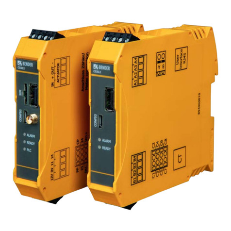
Bender CC612 User manual

Bender
Bender CC611 User manual
Bender
Bender PRC470 Series User manual

Bender
Bender CC612 User manual
Bender
Bender CC613 User manual
Bender
Bender ISOMETER isoMIL425HV User manual

