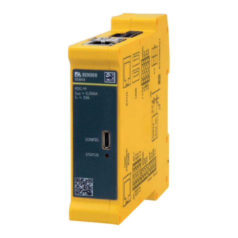
Bender CC613 User manual

CC613 charge controller
Charge controller for use in electric vehicle charging stations, wallboxes or street
light charging points
CC613_D00381_07_M_XXEN/02.2023 Manual EN

2 CC613_D003 1_07_M_XXEN/02.2023

CC613 charge controller
Table of contents
1Gene al inst uctions.........................................................................................5
1.1 How to use the manual..............................................................................................................................5
1.2 Indication of important instructions and information................................................................... 5
1.2.1 Signs and symbols........................................................................................................................................5
1.3 Service and Support.................................................................................................................................... 5
1.4 Training courses and seminars................................................................................................................ 5
1.5 Delivery conditions...................................................................................................................................... 6
1.6 Inspection, transport and storage..........................................................................................................6
1.7 Warranty and liability.................................................................................................................................. 6
1. Disposal of Bender devices.......................................................................................................................6
1.9 Safety................................................................................................................................................................. 7
2Function.............................................................................................................8
2.1 Intended use...................................................................................................................................................
2.2 Device features (depending on the variant)......................................................................................
2.3 Product description..................................................................................................................................... 9
2.4 Functional description................................................................................................................................9
2.5 General functions (depending on the variant)..................................................................................9
2.6 Temperature monitoring - Load current and cooling monitoring...........................................10
2.7 LED indications............................................................................................................................................11
3Dimensions and mounting............................................................................ 12
4Connection...................................................................................................... 13
4.1 Connection plug connections...............................................................................................................13
4.2 Wiring diagram............................................................................................................................................14
4.3 Connectivity..................................................................................................................................................17
4.3.1 Master/slave connection ........................................................................................................................ 17
4.3.2 Interfaces....................................................................................................................................................... 17
4.3.3 Power contactor connection..................................................................................................................17
4.3.4 PE monitoring..............................................................................................................................................19
4.3.5 Control Pilot (CP) and Proximity Pilot connections (PP).............................................................. 20
4.3.6 I/O extension (depending on the variant).......................................................................................21
4.3.7 Emergency opener.................................................................................................................................... 21
4.3. Residual direct current monitoring module (RDC-M)...................................................................21
4.3.9 Connectivity with Modbus meters...................................................................................................... 21
CC613_D003 1_07_M_XXEN/02.2023 3

Table of contents
4.3.10 Gateway variants with modem.............................................................................................................21
5Congu ation and testing............................................................................. 23
5.1 Conguration (depending on the variant)....................................................................................... 23
5.2 Local conguration of parameters...................................................................................................... 23
5.3 Remote conguration of parameters ................................................................................................25
5.4 Factory settings...........................................................................................................................................25
5.5 Testing and system boot process.........................................................................................................26
5.6 Connectivity to the backend................................................................................................................. 26
5.7 Plug locking and unlocking................................................................................................................... 27
5. Authorisation and charging................................................................................................................... 27
6Technical data.................................................................................................28
6.1 Declaration of conformity.......................................................................................................................32
6.2 Standards and approvals.........................................................................................................................32
6.3 Ordering information................................................................................................................................32
6.4 Revision history...........................................................................................................................................33
4 CC613_D003 1_07_M_XXEN/02.2023

CC613 charge controller
1 Gene al inst uctions
1.1 How to use the manual
ADVICE
This manual is intended for qualied personnel working in electrical engineering and electronics!
Part of the device documentation in addition to this manual is the enclosed supplement "Safety
instructions for Bender products".
ADVICE
Read the operating manual before mounting, connecting and commissioning the device. Keep the
manual within easy reach for future reference.
1.2 Indication of impo tant inst uctions and info mation
DANGER
Indicates a high risk of danger that will result in death or serious injury if not avoided.
WARNING
Indicates a medium risk of danger that can lead to death or serious injury if not avoided.
CAUTION
Indicates a low-level risk that can result in minor or moderate injury or damage to property if not
avoided.
Information can help to optimise the use of the product.
1.2.1 Signs and symbols
Disposal Protect from moisture Protect from dust
Temperature range Recycling RoHS directives
1.3 Se vice and Suppo t
Information and contact details about customer service, repair service or eld service for Bender devices are
available on the following webside: Fast assistance | Bender GmbH & Co. KG.
1.4 T aining cou ses and semina s
Regular face-to-face or online seminars for customers and other interested parties:
www.bender.de -> Fachwissen -> Seminare.
CC613_D003 1_07_M_XXEN/02.2023 5

General instructions
1.5 Delive y conditions
The conditions of sale and delivery set out by Bender GmbH & Co. KG apply. These can be obtained in printed
or electronic format.
The following applies to software products:
Die Elektroindustrie
"Software clause in respect of the licensing of standard software as part of deliveries,
modications and changes to general delivery conditions for products and services in the
electrical industry"
1.6 Inspection, t anspo t and sto age
Check the shipping and device packaging for transport damage and scope of delivery. In the event of
complaints, the company must be notied immediately, see "Technical support: Service and support".
The following must be observed when storing the devices:
1.7 Wa anty and liability
Warranty and liability claims for personal injury and property damage are excluded in the case of:
•Improper use of the device.
•Incorrect mounting, commissioning, operation and maintenance of the device.
•Failure to observe the instructions in this operating manual regarding transport, commissioning, operation
and maintenance of the device.
•Unauthorised changes to the device made by parties other than the manufacturer.
•Non-observance of technical data.
•Repairs carried out incorrectly.
•The use of accessories or spare parts that are not provided, approved or recommended by the
manufacturer.
•Catastrophes caused by external inuences and force majeure.
•Mounting and installation with device combinations not approved or recommended by the manufacturer.
This operating manual and the enclosed safety instructions must be observed by all persons working with
the device. Furthermore, the rules and regulations that apply for accident prevention at the place of use must
be observed.
1.8 Disposal of Bende devices
Abide by the national regulations and laws governing the disposal of this device.
For more information on the disposal of Bender devices, refer to
www.bender.de -> Service & Support.
6 CC613_D003 1_07_M_XXEN/02.2023

CC613 charge controller
1.9 Safety
If the device is used outside the Federal Republic of Germany, the applicable local standards and regulations
must be complied with. In Europe, the European standard EN 50110 applies.
DANGER Risk of fatal injury due to electric shock!
Touching live parts of the system carries the risk of:
•Risk of electrocution due to electric shock
•Damage to the electrical installation
•Destruction of the device
Before installing the device and before working on its connections, make sure that the installation
has been de-energised. The rules for working on electrical systems must be observed.
CC613_D003 1_07_M_XXEN/02.2023 7

Function
2 Function
Local access to charge controller
Local access to the charge controller is possible either as the operator or as the manufacturer. Further
details are described in chapter 5.1.1. perator access is possible via the http://192.168.123.123/
operator:
•User name: operator
•Password: yellow_zone
The Manufacturer can access the manufacturer area via the URL http://192.168.123.123/manufacturer:
•User name: manufacturer
•Password: orange_zone
The default passwords should be changed to prevent unauthorised access.
2.1 Intended use
The CC613 charge controller, hereinafter referred to as "charge controller", is the main component of a
charging system. It is intended for use in electric vehicle charging stations, wallboxes or street light charging
points. The charge controller controls type 1 and type 2 socket-outlets as well as attached cables. It enables a
setup that complies with the requirements of current standards, e.g. IEC 61 51-1 and IEC 62955.
2.2 Device featu es (depending on the va iant)
•Charge controller in accordance with IEC 61 51-1 (charging mode 3)
•Congurable master and slave operation
Setting up charging stations with two charging points:
– 1 charge controller as data gateway with 4G modem
– 1 charge controller as slave without 4G modem
•Dynamic load management to optimally distribute the available power among all charging points and
signal the maximum power available in each case to the vehicle
•Residual direct current monitoring module (external RCD type A required), dierent cable lengths can be
selected
•Integrated emergency opener for actuator control (locking/unlocking) and monitoring of the 12 V supply
voltage
•Can be integrated in single- or three-phase systems up to 0 A
•OCPP 1.5 and OCPP 1.6 compliant with JSON, SOAP
•Supported mobile networks: 4G (LTE), 3G (UMTS) and 2G (GSM) with an integrated 4G modem
•3 USB interfaces:
– 1 CONFIG interface for local conguration and installation of software updates
– 2 USB host interfaces
•Control Pilot and Proximity Pilot communication
•Congurable support for additional SCHUKO socket-outlets
•Meter interface: Modbus TCP and RTU
•External Modbus interface (second meter for dynamic load management)
•User interface modules for customer-specic applications (e.g. RFID, LED, antenna)
CC613_D003 1_07_M_XXEN/02.2023

CC613 charge controller
•Congurable 2-channel input/output extension interface for additional functionality
•Internal temperature sensor to reduce the charging current depending on the ambient temperature
•ISO 1511 Powerline Communication (PLC) for plug & charge and load management systems
•ISO 1511 Powerline Communication (PLC) for plug & charge or autocharge
•Ethernet interface
2.3 P oduct desc iption
The charge controller primarily controls the charging process of an electric vehicle and monitors the internal
hardware of charging systems such as the meter, the user interface module or the socket-outlet. It can
be operated as an "always-on system" that is always connected to a mobile network. The master variant
supports 4G mobile networks.
Communication with a backend system is possible via the OCPP application protocol. All specied messages
in OCPP are supported as well as some vendor-specic extensions based on the DataTransfer message.
Integration tests with the backend implementations of providers (e.g. has-to-be, Virta and NewMotion) have
been carried out successfully. See chapter "Ordering information".
2.4 Functional desc iption
The charging system consists of an RCD type A and a contactor. These are directly connected to a type 1 or
type 2 socket-outlet, or to a permanently mounted cable with a type 1 or type 2 plug (see chapter "Wiring
diagram").
2.5 Gene al functions (depending on the va iant)
•The charging system can be equipped with a meter. A Modbus meter is required to digitally read the
energy consumption. The Modbus RTU lines are attached directly to the device.
•A 12 V power supply is needed for operation.
•An RFID module can be used for easy user interaction.
•Current ow toward the vehicle is released by enabling the contactor via an integrated 230 V control relay
in the charge controller.
•Using a micro SIM card (not included in the scope of delivery):
The SIM card slot (available on data gateways with a 4G modem only) is located on the charge controller
front panel. The SIM card can have a PIN number which can be congured via the Ope ato tab. The APN
settings for the SIM card can also be congured via the Ope ato tab.
•Data gateways with a 4G modem feature a connection for a 4G antenna on the front panel.
•For residual current detection in an AC charging system, the charge controller features an integrated
residual direct current monitoring module (RDC-M) which uses an externally connected measuring current
transformer. With integrated monitoring of the DC residual current, only an RCD type A is required in the
charging system.
•Data exchange between the electric vehicle and the charging system is possible via ISO 1511 -compliant
Powerline Communication (PLC).
CC613_D003 1_07_M_XXEN/02.2023 9

Function
•Dynamic load management (DLM):
The charge controller comes with DLM software, which can be fully used, independent of a backend
connection. It detects which charging current is applied to which phase and thus prevents the occurrence
of peak loads and unbalanced loads. Maximum number of charging points in a network: 250.
•Data management and control functionality of the charge controller:
– Termination of the charging process after tripping the residual current protective device (RCD) due to a
residual current.
– Detection of critical residual currents by the RCM sensor. For the vehicle owner, this can serve as an early
warning, provided that the charge controller is connected to an energy management system and that it
supports this function.
•External Modbus interface for advanced control of the controller via an energy management system,
independent of a backend connection.
The charge controller with residual direct current monitoring module (RDC-M) only works in
combination with the measuring current transformer (to be ordered separately).
WARNING
CAUTION! Risk of damage when pulling out the measuring current
transformer plug! If the measuring current transformer plug is
pulled out using too much force, the enclosure and the internal
components may be damaged. Use needle-nose pliers to unlock
the measuring current transformer plug.
2.6 Tempe atu e monito ing - Load cu ent and cooling monito ing
The charge controller is equipped with a temperature sensor, which allows the temperature in the
environment of the charge controller to be estimated. Based on this estimation, it is possible to dynamically
reduce the charging current or even suspend charging. This feature can serve to maintain the temperature
inside the enclosure within the permissible range for the components used in a charging system. Basic
settings can be made via the Manufactu e tab.
The actual temperature is aected by heat generated by the charge controller itself.
10 CC613_D003 1_07_M_XXEN/02.2023

CC613 charge controller
2.7 LED indications
STATUS LED
Front plate
Orange Power on/system not ready for operation
Blue System is starting
Green System started, not yet ready for operation
Flashing green System running, system ready for operation
Red System error
Ethe net
Terminal D
O No Ethernet connection
Steady green Ethernet connection at 100 Mbit s
Flashing green Data exchange at 100 Mbit s
Steady yellow Ethernet connection at 10 Mbit s
Flashing yellow Data exchange at 10 Mbit s
CC613_D003 1_07_M_XXEN/02.2023 11

Dimensions and mounting
3 Dimensions and mounting
Dimension diag am
23,5
111 (112,3*)
99
Dimensions in mm acc. to ISO 276 - m
* Dimensions incl. antenna socket
Mounting
DIN rail mounting
Lateral distance to other equipment: 6 mm (self-heating)
In the horizontal mounting position, the max. operating temperature is reduced by 15 °C (refer to " ther"
in chapter "Technical data").
12 CC613_D003 1_07_M_XXEN/02.2023

CC613 charge controller
4 Connection
Connection conditions
DANGER System parts may be live
(charge controller terminals up to 230 , charging station 400 )
Electric shock
Before touching system parts, ensure that it has been de-energised.
CAUTION Sharp-edged terminals
Cut injuries
Handle enclosure and terminals with care.
Information:
•PE is connected to "0V"; reference level for Control Pilot (CP communication) must be at the same level
as the power supply (IEC 61851 series of standards).
•The Ethernet shield is directly connected to PE.
•The charge controller is supplied with power from a 12 V main voltage source at the +12V and 0V
connections.
•Lay lines only inside the wallbox and not in parallel with power cables.
•Connect external Modbus to terminal block I using a shielded cable.
•External Modbus must be terminated by the customer with a terminating resistor of 120 Ω.
•Cable lengths (except Modbus, Ethernet, Power IN and charging cable): < 3m.
•Maximum cable length Ethernet/Fast Ethernet: 100m.
•Maximum cable length Modbus: 250m.
For further information on connection, refer to the manuals of the accessories
(Example CTBC17P-03).
4.1 Connection plug connections
Image: Connection type 1 plug Image: Connection type 2 plug
CC613_D003 1_07_M_XXEN/02.2023 13

Connection
4.2 Wi ing diag am
Cha ging system with type 2 socket-outlet
14 CC613_D003 1_07_M_XXEN/02.2023

CC613 charge controller
Legend
A Connection measuring current transformer (CT) m RCD type A
B 12 V supply, PE, Modbus meter, CP, PP n Supply voltage DC 12 V
C 2x USB type A (1, 2) o Measuring current transformer (CT) with
plug
D Connection Ethernet (ETH1) p Contactor
E Antenna socket 4G (only available for variants with 4G modem1) q Type 2 socket-outlet
F Configuration interface
G Micro SIM card slot (only available for variants with 4G modem1)
H Weld check, relay for contactor control rated for 230 V 4 A
I External Modbus (galvanic separation)
J Locking, control relay GPIO, optocoupler input
K Connection user interface (HMI) (not available with HEM-X2 variant)
L STATUS LED
1Data gateways with 4G modem: CC613-ELM4PR-M and CC613-ELM4PR
Te minal assignment (depending on the va iant)
0 V Input 0 V GND2 External Modbus GND (shield connected on one side)
+12 V Supply voltage +12 V B2 External Modbus B (galvanic separation)
PE Input PE
I
A2 External Modbus A (galvanic separation)
PE Input PE
B Mod. Modbus meter B In- Opto 1 In-: Optocoupler input 12 V negative
A Mod. Modbus meter A IN+ Opto 1 In+: Optocoupler input 12 V positive
CP Control Pilot A Actuator A: Locking actuator output negative
B
PP Proximity Pilot B Actuator B: Locking actuator output positive
HS2 Actuator HS2: Locking input actuator switch
WA Weld check input L1 HS1 Actuator HS1: Locking 12 V output actuator switch
23 Relay 23: Switching contact contactor 14 Relay 14: Relay contacts GPIO (12 V)
WB Weld check input N
J
13 Relay 13: Relay contacts GPIO (12 V)
H
24 Relay 24: Switching contact contactor
ADVICE
CAUTION! Switching contact contactor and weld check at terminal H are only suitable for mains
voltage (230 V)! Not permitted for SELV/PELV voltages.
CC613_D003 1_07_M_XXEN/02.2023 15

Connection
Connection locking actuato s
A S1 B S2Type 2 socket-outlets (actuator type) Actuator
Socket-outlet actuator wiring
•Mennekes (31016, 31023, 31024, 31038)
•Bals (801191-801195, 80300, 9743205000,
9743211000)
•Walther Werke (9743211000)
•Harting
Wire 3 ( ) Wire 1 ( ) Wire 2 ( )
•Walther Werke Eco Slim 32 A (9743205180) with
connection cable (790000001)
Hella
Wire 1
(black)
Wire 3
(blue)
Wire 2
(red)
•Phoenix Contact (1624129) Küster BU BN BU YE BU RD BU GN
•Phoenix Contact ( EV-T2M3SM-E-LOCK12V) Phoenix
Contact BU BN BU YE BU RD BU GN
Example Hella actuato
Example Küste
16 CC613_D003 1_07_M_XXEN/02.2023

CC613 charge controller
4.3 Connectivity
4.3.1 Maste /slave connection 1
The charge controller serves as a data gateway. Master/slave operation requires the USB conguration
interface (micro USB 2.0, master) to be connected to the USB type A interface (slave) via a USB cable. The
master assumes the role of the OCPP backend for the slave. It connects each slave as an additional charging
point to the backend.
The master or slave role is assigned to a charge controller within the Manufactu e conguration interface.
A reboot can then be triggered and the devices can be connected via a micro USB cable (master: micro USB/
slave: USB type A). Usually, the devices connect automatically. Local access to the master/slave combination
is then only possible via the slave device. The IP address of the master must be assigned to each slave as
OCPP host name. Port 1600 must be used as an OCPP port to establish a connection with the master.
The additional IP address 192.16 .125.124 is assigned to the master via the Ope ato tab (without assigning
a default gateway). The slave uses the IP address 192.16 .125.125 to establish a connection with the master.
Master and slave conguration can be accessed via a selection page on the conguration website of the slave
(e.g. http://192.16 .123.123).
4.3.2 Inte faces
USB congu ation inte face (CONFIG)
The USB conguration interface (CONFIG) on the front panel of the charge controller can be connected to a
conventional laptop, PC or tablet computer via a micro USB cable. This interface allows local conguration
of the charge controller. In addition, it enables software updates to be installed. The web interface can be
accessed via the IP address 192.16 .123.123.
Ethe net inte face (depending on the va iant)
The charge controller can be connected to an existing Ethernet network via an Ethernet interface.
WiFi inte face (via USB WiFi adapto )
By using an USB WiFi adaptor, it is possible to set up a backend connection via WiFi network.
For further information on conguration descriptions and interfaces, see chapter "Conguration and testing".
4.3.3 Powe contacto connection
Contacto connection
The charge controller controls the contactor, which in turn releases the current ow to the vehicle. The
contactor is controlled via a relay in the charge controller, the contacts of which are rated for 230 V/4 A (see
chapter "Wiring diagram").
1Only for variants with OCPP (see ordering information)
CC613_D003 1_07_M_XXEN/02.2023 17

Connection
Alte native connection fo powe contacto
Alternatively, the power contactor can be controlled via the customer's own AC or DC mains part in
combination with the 230 V relay (terminal H: 23, 24).
Detail of wiring diagram chapter "Charging system with type 2 socket-outlet"
1 Customer mains part (AC/DC)
ADVICE
Caution: DC residual currents caused by the contactor or the control relay are not detected.
1 CC613_D003 1_07_M_XXEN/02.2023

CC613 charge controller
Weld check
By means of the measuring lines (terminal H: WA, WB) impermissible closing of the contactor contacts, e.g.
welding/sticking, can be detected.
Wiring diagram
ADVICE
Risk of a short circuit! For the coupling of terminals WA and WB, devices for protection against a
short circuit can be omitted in accordance with DIN VDE 0100-430 if the wiring is carried out in
such a manner as to reduce the risk of a short circuit to a minimum. (Short-circuit-proof and earth-
fault-proof wiring is recommended). The connecting lines WA and WB to the power supply system
to be monitored must be designed as spur lines. No load current may be conducted through the
terminals.
4.3.4 PE monito ing
PE monito ing
PE monitoring checks whether there is a connection from the charge controller to PE. For this purpose,
WA must be connected to L1. Due to the capacitance of the supply line, the supply line length that can
be checked is limited. To ensure correct functionality of the PE monitoring, L1 must be tapped behind the
measuring current transformer and before the power contactor.
CC613_D003 1_07_M_XXEN/02.2023 19

Connection
Wiring diagram
ADVICE
PE monitoring does not replace tests (e.g. protective earth resistance).
ADVICE
The Ethernet shield and the USB shield are directly connected to PE. This must be taken into
account in the test!
ADVICE
HV test: WA is coupled to PE via a protective circuit and with approximately 140 kΩ.
Above 500 V, a leakage current ows to PE.
Test voltages above AC 1000 V/1 s are not permissible!
4.3.5 Cont ol Pilot (CP) and P oximity Pilot connections (PP)
The PP contact identies the connected charging cable and limits the maximum possible charging current.
The CP contact enables communication with the vehicle (see IEC61 51 series of standards).
PP is not required if the charging cable is permanently installed.
20 CC613_D003 1_07_M_XXEN/02.2023
Other manuals for CC613
1
Table of contents
Other Bender Controllers manuals
Bender
Bender ISOMETER isoMIL425HV User manual
Bender
Bender RC48C User manual
Bender
Bender CC612 EV User manual
Bender
Bender CC612 User manual

Bender
Bender CC612 User manual
Bender
Bender CC613 User manual
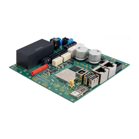
Bender
Bender ICC1324 User manual
Bender
Bender ISOMETER isoPV425 with AGH420 User manual

Bender
Bender CC611 User manual
Bender
Bender PRC470 Series User manual
