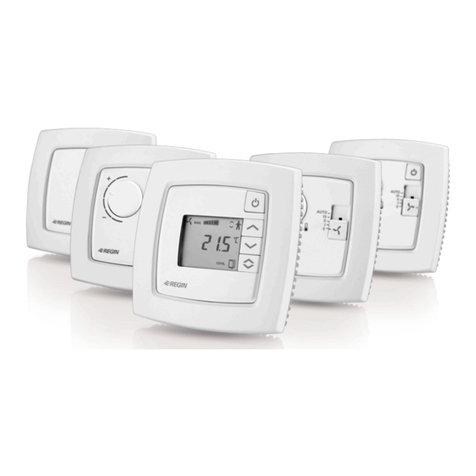
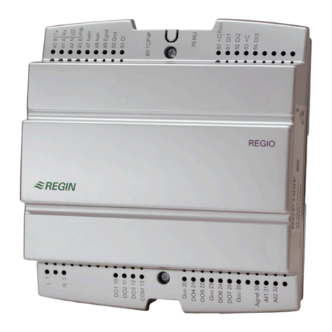
Regin Regio Eddo User manual

EN INSTRUCTION
REGIOEEDO
IN20006 REV. D, 2019-02-26
NNoottee!! More information a out the product can e found in the manual,
which is availa le for download from www.regincontrols.com
CCaauuttiioonn!! Read and understand the instruction efore using the product.
CCaauuttiioonn!! Ensure that the installation complies with local safety
regulations.
WWaarrnniinngg!! Before installation or maintenance, the power supply must first
e disconnected in order to prevent potentially lethal electric shocks! In-
stallation or maintenance of this unit should only e carried out y quali-
fied personnel. The manufacturer is not responsi le for any eventual
damage or injury caused y inadequate skills during installation, or through
removal of or deactivation of any security devices.
Box contents
The RegioEedo box contains one baseplate with a pre-mounted partition
that separates the 230 V and 24 V controller connections (A) one
controller unit (B) and two terminal protection covers (C).
Mounting
The controller is mounted either on a DIN rail inside a cabinet or on a
wall above a false ceiling. The controller form factor is EURO norm
which makes it fit into a standard EURO norm cabinet.
WWaarrnniinngg!! When mounting the controller on a DIN rail, the controller
must e placed inside a ca inet to prevent electric shock. When mounting
the controller on a wall, the terminal protection covers must e attached
to prevent electric shock.
DIN rail mounting inside a ca inet
To mount the controller:
1. Pull out the fastener.
2. Attach the controller to the rail.
3. Push in the fastener to secure the controller.
Wall mounting
To mount the controller:
1. Attach the baseplate to the wall using screws.
2. Pull out the fastener and attach the controller to the baseplate and
then push in the fastener to secure the controller.
A
B
C x 2
RegioEedo 1

3. Check that the pre-mounted partition between the 230 V and 24 V
terminals is securely attached.
4. Attach the terminal protection covers to the baseplate and then
secure the covers using the pre-mounted Torx T20 screws.
Wiring
The following wiring diagram exemplifies controller connections usage
and the following table describes the controller connections and their
applicability.
CCaauuttiioonn!! Ensure that the ca ling is securely attached to the aseplate,
and that the 230 V ca ling is separated from the extra-low voltage (ELV)
ca ling.
Terminal №
and
designator
Type Description
1 L Supply voltage 230 V AC supply voltage
2 N Supply voltage
(neutral)
230 V AC supply voltage (neutral).
10 N1
12 N2
20 N3-5
Neutral Digital output neutral.
Terminal №
and
designator
Type Description
11 DO1d
13 DO2d
Digital output Triac output used for valve, blinds, or lighting
control, or for alarms or forced ventilation.
21 DO3c
22 DO4c
23 DO5c
Digital output Relay output used for 3-speed fan control.
30 N
31 A
32 B
RS485 communi-
cation port
RS485 connector used for communication via
BACnet, or for master/slave communication via
Exoline or Modbus.
This connection is galvanically isolated.
40 N
41 A
42 B
RS485 communi-
cation port
RS485 connector used for communication via
BACnet, or for master/slave communication via
Exoline or Modbus.
This connection is not galvanically isolated.
Ext. Disp. External display
communication
port
4P4C modular connector used for communica-
tion with an ED-RU-... room unit.
Ethernet commu-
nication port
8P8C modular connector used for Ethernet -
TCP/IP communication.
50 AGND
52 AGND
54 AGND
70 AGND
72 AGND
74 AGND
76 AGND
Analog ground Signal ground for analog inputs and outputs.
51 AI1c Analog input Input used for change-over detection or for
temperature sensor.
53 AI2b
55 AI3b
Analog input Input used for CO2, condensation, or relative
humidity sensor.
56 POa Power output 24 V DC voltage output used for powering a
CO2or condensation sensor.
60 GND
62 GND
64 GND
66 GND
Digital ground Signal ground for digital inputs.
61 DI1b
63 DI2b
65 DI3b
Digital input Input used for presence, open window, or
change-over detection.
67 CI1a Condensation
input
Input dedicated for Regin’s condensation de-
tector KG-A/1.
71 AO1a
73 AO2a
75 AO3a
77 AO4a
Analog output Output used for valve, damper, or EC fan
control.
N | -
L | +
1
2
+24 V DC | POa56
230 V AC
DO5c
DO4c
DO3c
N3-5
DO2d
N2
DO1d
10N1
11
12
13
20
21
22
23
AO4a
AGND
AO3a
AGND
AO2a
AGND
77
76
75
AO1a
AGND
74
73
72
71
70
DI3b
GND
DI2b
GND
DI1b
GND
GND
CI1a67
66
65
64
63
62
61
60
AGND
AI1c
AGND
AI2b
AGND
AI3b55
54
53
52
51
50
Ext.
Disp.
Eedo
230 V AC
Ethernet
A (COM-)
B (COM+)
N
40
41
42
{
P2
A (COM-)
B (COM+)
N
30
31
32
{
P1
M
I
III
II
°C
PT1000
KG-A/1
GND
0...10 V
N
L
G0
0...10 V
G
CTRTA
RegioEedo 2

The ED-RU-… room unit is connected to the controller by using a Regin
EDSP-K3 cable as shown in the following wiring diagram.
Terminal № and designator EDSP-K3 wire color
10 G Black
11 G0 White
42 A Yellow
43 B Brown
Configuration and commissioning
It is recommended that Application tool is used to perform configuration
and commissioning. A room unit with display can also be used by
modifying the parameters that are accessed via the parameter menu in
the display. The display parameters are listed in the manual.
Technical data
General data
Supply voltage 230 V ~ (207…253 V ~ 50/60 Hz)
Memory backup Backup of memory and real-time clock function
Battery type CR2032 replaceable lithium cell
Protection class IP20
Protection class, with ter-
minal protection covers
IP30
Protection class, electrical Class II
Ambient humidity Max. 95 % RH (non-condensing)
Ambient temperature 0…55 °C
Number of DIN modules 8.5
Dimensions, controller unit
with terminal blocks
(WxHxD)
149 x 121 x 58 mm
Dimensions, controller unit
with baseplate and terminal
protection covers (WxHxD)
153 x 202 x 68 mm
Operating system EXOrealC
I/Os
Analogue input b (AIb) 0…10 V DC
Analogue input c (AIc) PT1000
Digital input b (DIb) Sourcing input type, GND is ref
Condensation input a (CIa) Input dedicated for Regin’s condensation detec-
tor KG-A/1
Analogue output a (AOa) 0…10 V DC, max. 5 mA, short-circuit proof
Digital output c (DOc) Relay output 230 V AC, max. 3 A
Digital output d (DOd) Triac output 230 V AC, max. 300 mA
Digital outputs, total max.
current (fuse)
6.3 A (6.3 AT 5x20 mm)
Power output a (POa) 24 V DC, max. 50 mA
RS485 communication ports
Default protocol EXOline
Supported protocols EXOline, Modbus, BACnet MS/TP
Port isolation P1: Galvanic common mode voltage, max. 150 V
P2: No
Ethernet communication port
Default protocol EXOline
Supported protocols EXOline, Modbus IP, BACnet/IP
This product carries the CE-mark. More information is available at
www.regincontrols.com.
Documentation and Application tool
All documentation and Application tool can be downloaded from www.
regincontrols.com
Contact
AB Regin Box 116 428 22 Kållered Sweden
Tel: +46 31 720 02 00 Fax: +46 31 720 02 50
www.regincontrols.com [email protected]
SE INSTRUKTION
REGIOEEDO
NNootteerraa!! Mer information om produkten finns i manualen, som är tillgäng-
lig för nedladdning från www.regincontrols.com
OO sseerrvveerraa!! Läs och förstå instruktionen innan du använder produkten.
OO sseerrvveerraa!! Se till att installationen uppfyller lokala
säkerhets estämmelser.
VVaarrnniinngg!! Innan installation eller underhåll måste matningsspänningen först
kopplas från för att undvika potentiellt dödliga elstötar! Installation eller
underhåll av denna enhet ska endast utföras av kvalificerad personal. Till-
verkaren är inte ansvarig för eventuella skador som orsakas av felaktig in-
stallation och/eller inaktivering eller orttagning av säkerhetsanordningar.
Kartongens innehåll
RegioEedo-kartongen innehåller ett bakstycke med en förmonterad
partition som avskiljer regulatorns 230 V- och 24 V-anslutningar (A) en
regulatorenhet (B) och två plintskydd (C).
B
A
G0
10G
11
42
43
ED-RU-...
Ext.
Disp.
EDSP-K3
RegioEedo 3
Montering
Regulatorn monteras antingen på en DIN-skena i ett skåp eller på en
vägg ovanför ett undertak. Regulatorns formfaktor håller EURO-norm
vilket gör att den passar in i standard EURO-normskåp.
VVaarrnniinngg!! När regulatorn monteras på en DIN-skena så måste den place-
ras inuti ett skåp för att förhindra elstötar. När regulatorn monteras på en
vägg så måste plintskydden fästas för att förhindra elstötar.
Montering på DIN-skena inuti ett skåp.
För att montera regulatorn:
1. Dra ut fästet.
2. Fäst regulatorn på skenan.
3. Skjut in fästet för att säkra regulatorn.
Väggmontering
För att montera regulatorn:
1. Fäst bakstycket på väggen med hjälp av skruvar.
2. Dra ut fästet och fäst regulatorn på bakstycket. Skjut sedan in fästet
för att säkra regulatorn.
3. Kontrollera att den förmonterade partitionen mellan 230 V- och 24
V-anslutningarna är ordentligt fastsatt.
4. Fäst plintskydden på bakstycket och säkra dem sedan med hjälp av
de förmonterade Torx T20-skruvarna.
Inkoppling
Följande kopplingsschema exemplifierar användning av
regulatoranslutningar och följande tabell beskriver regulatorns
anslutningar och deras tillämpbarhet.
OO sseerrvveerraa!! Se till att ka laget är ordentligt fastsatt på akstycket och att
230 V-ka laget är avskilt från extra-lågspänningska alaget (ELV).
A
B
C x 2
RegioEedo 4

Plintnum-
mer och
beteckning
Typ Beskrivning
1 L Matningsspän-
ning
230 V AC matningsspänning
2 N Matningsspän-
ningsnolla
230 V AC matningsspänningsnolla.
10 N1
12 N2
20 N3-5
Referens Referens för digital utgång.
Plintnum-
mer och
beteckning
Typ Beskrivning
11 DO1d
13 DO2d
Digital utgång Triacutgång som används för styrning av ventil,
persienner eller belysning, eller för forcerad
ventilation eller larm.
21 DO3c
22 DO4c
23 DO5c
Digital utgång Reläutgång som används för styrning av 3-
stegsfläkt.
30 N
31 A
32 B
RS485-kommuni-
kationsport
RS485-kontakt som används för kommunika-
tion via BACnet eller för master/slave-kommu-
nikation via Exoline eller Modbus.
Denna anslutning är galvaniskt isolerad.
40 N
41 A
42 B
RS485-kommuni-
kationsport
RS485-kontakt som används för kommunika-
tion via BACnet eller för master/slave-kommu-
nikation via Exoline eller Modbus.
Denna anslutning är inte galvaniskt isolerad.
Ext. Disp. Kommunikation-
sport för extern
display
Modulär 4P4C-kontakt som används för kom-
munikation med en ED-RU-... rumsenhet.
Ethernet-kommu-
nikationsport
Modulär 8P8C-kontakt som används för Ether-
net-TCP/IP-kommunikation.
50 AGND
52 AGND
54 AGND
70 AGND
72 AGND
74 AGND
76 AGND
Analog jord Signaljord för analoga ingångar och utgångar.
51 AI1c Analog ingång Ingång som används för change-over-detekter-
ing eller för temperaturgivare.
53 AI2b
55 AI3b
Analog ingång Ingång som används för CO2-, kondens- eller
relativ fuktighetsgivare.
56 POa Spänningsutgång 24 V DC spänningsutgång som används för att
driva en CO2- eller kondensgivare.
60 GND
62 GND
64 GND
66 GND
Digital jord Signaljord för digitala ingångar.
61 DI1b
63 DI2b
65 DI3b
Digital ingång Ingång som används för närvaro-, öppet föns-
ter- eller change-over-detektering.
67 CI1a Kondensingång Ingång avsedd för Regins kondensgivare KG-
A/1.
71 AO1a
73 AO2a
75 AO3a
77 AO4a
Analog utgång Utgång som används för styrning av ventil,
spjäll eller EC-fläkt.
ED-RU-... rumsenheten ansluts till regulatorn med hjälp av en Regin
EDSP-K3 kabel vilket visas i följande kopplingsschema.
Plintnummer och beteckning EDSP-K3 trådfärg
10 G Svart
11 G0 Vit
42 A Gul
43 B Brun
Konfigurering och driftsättning
Det rekommenderas att Application tool används för att utföra
konfigurering och driftsättning. En rumsenhet med display kan också
användas genom att modifiera de parametrar som nås via displayens
parametermeny. Displayparametrarna är listade i manualen.
Tekniska data
Generella data
Matningsspänning 230 V ~ (207…253 V ~ 50/60 Hz)
Minnesbackup Backup av minne och realtidsklocka
Batterityp Utbytbar lithiumcell CR2032
Skyddsklass IP20
Skyddsklass, med
plintskydd
IP30
Skyddsklass, elektrisk Klass II
Omgivande luftfuktighet Max. 95 % RH (icke-kondenserande)
Omgivningstemperatur 0…50 °C
Antal DIN-moduler 8.5
N | -
L | +
1
2
+24 V DC | POa56
230 V AC
DO5c
DO4c
DO3c
N3-5
DO2d
N2
DO1d
10N1
11
12
13
20
21
22
23
AO4a
AGND
AO3a
AGND
AO2a
AGND
77
76
75
AO1a
AGND
74
73
72
71
70
DI3b
GND
DI2b
GND
DI1b
GND
GND
CI1a67
66
65
64
63
62
61
60
AGND
AI1c
AGND
AI2b
AGND
AI3b55
54
53
52
51
50
Ext.
Disp.
Eedo
230 V AC
Ethernet
A (COM-)
B (COM+)
N
40
41
42
{
P2
A (COM-)
B (COM+)
N
30
31
32
{
P1
M
I
III
II
°C
PT1000
KG-A/1
GND
0...10 V
N
L
G0
0...10 V
G
CTRTA
B
A
G0
10G
11
42
43
ED-RU-...
Ext.
Disp.
EDSP-K3
RegioEedo 5

Mått, regulatorenhet med
plintar (BxHxD)
149 x 121 x 58 mm
Mått, regulatorenhet med
bakstycke och plintskydd
(BxHxD)
153 x 202 x 68 mm
Operativsystem EXOrealC
I/Os
Analog ingång b (AIb) 0…10 V DC
Analog ingång c (AIc) PT1000
Digital ingång b (DIb) Strömmatande ingång, GND är ref
Kondensingång a (CIa) Ingång avsedd för Regins kondensgivare KG-A/
1.
Analog utgång a (AOa) 0...10 V DC, max. 5 mA, kortslutningsskyddad
Digital utgång c (DOc) Reläutgång 230 V AC, max. 3 A
Digital utgång d (DOd) Triacutgång 230 V AC, max. 300 mA
Digitala utgångar, totalt
max. ström (säkring)
6.3 A (6.3 AT 5x20 mm)
Spänningsutgång a (POa) 24 V DC, max. 50 mA
RS485-kommunikationsport
Förvalt protokoll EXOline
Stödda protokoll EXOline, Modbus, BACnet MS/TP
Portisolering P1: Isolationsspänning, max. 150 V
P2: Nej
Ethernet-kommunikationsport
Förvalt protokoll EXOline
Stödda protokoll EXOline, Modbus IP, BACnet/IP
Produkten är CE-märkt. Mer information finns på www.regincontrols.
com.
Dokumentation och Application tool
All dokumentation och Application tool kan laddas ner från www.
regincontrols.com
Kontakt
AB Regin Box 116 428 22 Kållered Sverige
Tel: +46 31 720 02 00 Fax: +46 31 720 02 50
www.regincontrols.com [email protected]
DE INSTALLATIONSANLEITUNG
REGIOEEDO
HHiinnwweeiiss!! Weitere Informationen zum Produkt finden Sie im Bedienhand-
uch, das Sie unter www.regincontrols.de runterladen können.
VVoorrssiicchhtt Lesen Sie diese Montageanleitung vor Einsatz des Produktes
durch.
VVoorrssiicchhtt Vergewissern Sie sich, dass die Installation die lokalen Sicher-
heitsanforderungen erfüllt.
WWaarrnnuunngg Vor der Installation oder der Wartung muss die Stromversor-
gung getrennt werden, um tödliche Stromschläge zu vermeiden. Montage
und Wartung dieses Geräts dürfen nur von Fachkräften durchgeführt wer-
den. Der Hersteller haftet nicht für Schäden, die durch mangelnde Fach-
kenntnisse ei der Installation und/oder Sicherheitsvorkehrungen, die
entfernt oder manipuliert wurden, verursacht werden.
Lieferumfang
Der RegioEedo Lieferumfang beinhaltet die Montageplatte mit den
Unterteilungen die den 230V-Bereich von dem 24V-Bereich trennt (A)
ein Regler separat in einer Verpackung (B) und 2 Abdeckungen (C)
Montage
Installieren Sie den Regler auf einer DIN-Schiene in einem
Schaltschrank oder auf die Wand in der Zwischendecke. Die
Abmessungen des Gehäuses besitzen EURO-Norm und passen daher in
Schaltschränke mit EURO-Norm.
WWaarrnnuunngg Wird der Regler auf einer DIN-Schiene montiert, so darf dies
nur innerthal eines Schaltschrankes erfolgen um Elektroschläge zu ver-
meiden. Wird der Regler auf der Wand montiert, so müssen die A de-
ckungen verwendet werden um Elektroschläge zu vermeiden.
Montage auf der DIN-Schienen im Schaltschrank
Montage des Reglers:
1. Ziehen Sie die Befestigung heraus.
2. Positionieren Sie den Regler auf der DIN-Schiene.
A
B
C x 2
RegioEedo 6

3. Drücken Sie den Befestiger herein um den Regler auf der Schiene zu
sichern.
Wandmontage
Montage des Reglers:
1. Befestigen Sie die Monategplatte auf der Wand mit Hilfe der
Schrauben.
2. Ziehen Sie die Befestigung heraus positionieren Sie den Regler auf
der Montageplatte und drücken Sie den Befestiger wieder herein um
den Regler zu sichern.
3. Vergewissern Sie sich dass die Trennung zwischen 230V-Bereich
und 24V-Bereich auch sicher positioniert ist.
4. Befestigen Sie die Abdeckplatten auf der Montageplatte und sichern
Sie diese mit den vorinstallierten Torx T20 Schrauben.
Verdrahtung
Das folgende Anschlussschema veranschaulicht die Verwendung der
Regleranschlüsse und die folgende Tabelle beschreibt deren
Verwendbarkeit.
VVoorrssiicchhtt Stellern Sie sicher, dass die Ka el sicher mit der Montageplatte
vert unden sind und dass die 230V Ka el von den Ka eln mit Niedervolt-
spannung (ELV) getrennt sind.
RegioEedo 7

Klemmen
Nr. und Be-
stimmung
Typ Beschreibung
1 L Versorgungs-
spannung
230 V AC Versorgungsspannung
2 N Versorgungs-
spannung
(Neutral)
Versorgungsspannung 230 V AC (Neutral)
10 N1
12 N2
20 N3-5
Neutral Digitalausgang (Neutral)
Klemmen
Nr. und Be-
stimmung
Typ Beschreibung
11 DO1d
13 DO2d
Digitalausgang Triac Ausgang für Ventil, Zwangslüftung, Alar-
me, Rollos oder Lichtkontrolle.
21 DO3c
22 DO4c
23 DO5c
Digitalausgang Relaisausgang vorrangig verwendet für 3-stufi-
ge Ventilatorregelung
30 N
31 A
32 B
RS485 Kommuni-
kationsschnittstel-
le
RS485 Anschluss für die Komunikation über
BACnet oder Master/Slave-Kommunikation
über EXOline oder Modbus.
Diese Verbindung ist nicht galvanisch getrennt.
40 N
41 A
42 B
RS485 Kommuni-
kationsschnittstel-
le
RS485 Anschluss für die Komunikation über
BACnet oder Master/Slave-Kommunikation
über EXOline oder Modbus.
Diese Verbindung ist nicht galvanisch getrennt.
Ext. Disp. Schnittstelle für
externes Display
4P4C modularer Steckverbinder für die Kom-
munikation mit einer ED-RU-... Fernbedienung.
Ethernet-
Schnittstelle
8P8C modularer Steckverbinder für Ethernet -
TCP/IP-Kommunikation.
50 AGND
52 AGND
54 AGND
70 AGND
72 AGND
74 AGND
76 AGND
Analog Masse Masse für analoge Ein- und Ausgänge
51 AI1c Analogeingang Eingang für Temperaturfühler oder Change-
Over-Erkennung
53 AI2b
55 AI3b
Analogeingang Eingang für CO2, Kondensation, oder Fühler
für relative Feuchte.
56 POa Stromausgang 24 V DC Versorgungsspannung Ausgang ver-
wendet für CO2oder Kondensationsfühler
60 GND
62 GND
64 GND
66 GND
Digitaleingang Signalmasse für Digitaleingänge
61 DI1b
63 DI2b
65 DI3b
Digitaleingang Eingang für Präsenzmelder, Fensterkontakt
oder Change-Over-Erkennung
67 CI1a Kondensations-
eingang
Eingang für Kondensationsmelder von Regin,
KG-A/1
71 AO1a
73 AO2a
75 AO3a
77 AO4a
Analogausgänge Ausgang für Ventil, Klappe oder EC-
Ventilatorregelung
Die ED-RU-... Fernbedienung wird mit dem Regler über das Kabel
EDSP-K3 verbunden wie im folgenden Diagramm angezeigt
Klemmen Nr. und Bestimmung EDSP-K3 Draht Farbe
10 G Schwarz
11 G0 Weiß
42 A Gelb
43 B Braun
Konfiguration und In etrie nahme
Für die Konfiguration und die INbetriebnahme wird die Verwendung
des Application Tool empfohlen. Sie können auch eine Fernbedienung
mit Display verwenden um Parameter zu verwenden. Dazu nutzen Sie
das Parametermenü. Die Displayparameter sind im Bedienhandbuch
aufgelistet.
Technische Daten
Allgemeine Daten
Versorgungsspannung 230 V ~ (207…253 V ~ 50/60 Hz)
Speicher Backup Backup von Speicher und Echtzeituhr
Batterietyp CR2032, austauschbare Lithiumbatterie
Schutzart IP20
Schutzklasse, mit
Abdeckungen
IP30
Schutzart, elektrisch Klasse 2
Umgebungsfeuchte Max. 95 % rel.F., (nicht kondensierend)
Umgebungstemperatur 0...55°C
Anzahl der DIN-Module 8.5
N | -
L | +
1
2
+24 V DC | POa56
230 V AC
DO5c
DO4c
DO3c
N3-5
DO2d
N2
DO1d
10N1
11
12
13
20
21
22
23
AO4a
AGND
AO3a
AGND
AO2a
AGND
77
76
75
AO1a
AGND
74
73
72
71
70
DI3b
GND
DI2b
GND
DI1b
GND
GND
CI1a67
66
65
64
63
62
61
60
AGND
AI1c
AGND
AI2b
AGND
AI3b55
54
53
52
51
50
Ext.
Disp.
Eedo
230 V AC
Ethernet
A (COM-)
B (COM+)
N
40
41
42
{
P2
A (COM-)
B (COM+)
N
30
31
32
{
P1
M
I
III
II
°C
PT1000
KG-A/1
GND
0...10 V
N
L
G0
0...10 V
G
CTRTA
B
A
G0
10G
11
42
43
ED-RU-...
Ext.
Disp.
EDSP-K3
RegioEedo 8

Abmessungen, Gehäuse
mit Klemmenleisten
(BxHxT)
149 x 121 x 58 mm
Abmessungen, Gehäuse
mit Montageplatte und Ab-
deckungen (BxHxT)
153 x 202 x 68 mm
Betriebssystem EXOrealC
E/As
Analogeingang b (AIb) 0…10 V DC
Analogeingang c (AIc) PT1000
Digitaleingang b (DIb) Quelle Eingangstyp, GND ist Referenz
Kondensationseingang a
(CIa)
Eingang für Kondensationsmelder von Regin,
KG-A/1
Analogausgang a (AOa) 0…10 V DC, max. 5 mA, kurzschlussfest,
Digitalausgang c (DOc) Relaisausgang: 230 V AC, max. 3 A
Digitalausgang d (DOd) Triac-Aisgang. 230 V AC, max. 300 mA.
Digitalausgang. total Maxi-
malstrom (Sicherung)
6.3 A (6.3 AT 5x20 mm)
Stromausgang a (POa) 24 V DC, max. 50 mA
RS485 Kommunikationsschnittstelle
Standardprotokoll EXOline
Unterstütztes Protokoll EXOline, Modbus, BACnet MS/TP
Schnittstellen-Trennung P1: Galvanische Trennung, Gleichtaktspannung.
max. 150V
P2: Nein
Ethernet-Schnittstelle
Standardprotokoll EXOline
Unterstütztes Protokoll EXOline, Modbus IP, BACnet/IP
Dieses Produkt trägt das CE-Zeichen. Mehr Information können Sie auf
www.regincontrols.de finden.
Dokumentation und Application Tool
Alle Dokumente und das Application Tool können auf www.
regincontrols.de runtergeladen werden.
Kontakt
Regin Controls Deutschland GmbH Haynauer Str. 49 12249 Berlin
Deutschland
Tel: +49 30 77 99 4-0 Fax: +49 30 77 99 4-13
www.regincontrols.de [email protected]
FR INSTRUCTION
REGIOEEDO
NNBB !! Pour plus d'informations sur le produit, veuillez consulter le manuel,
disponi le sur le site www.regincontrols.com
AAtttteennttiioonn !! Veuillez lire attentivement l'instruction avant d'utiliser le
produit.
AAtttteennttiioonn !! Assurez-vous que l'installation est conforme aux normes de
sécurité locales.
AAvveerrttiisssseemmeenntt !! Avant de procéder à l'installation ou à la maintenance
de l'appareil, il convient de couper l'alimentation afin d'éviter tout risque
de choc électrique. Les opérations d'installation et de maintenance doi-
vent être effectuées par un professionnel qualifié. Le fa ricant ne pourra
être tenu responsa le d'éventuels dommages ou lessures causés par une
installation défectueuse du produit, ou par la désactivation des dispositifs
de sécurité.
Contenu de la oîte
La boîte de RegioEedo contient un socle avec une séparation des fils en
230V et 24V (A) un régulateur (B) et 2 caches (C).
Montage
Le régulateur se monte sur un rail DIN dans une armoire ou sur un mur
dans le faux plafond. Le boîtier est compatible avec toutes les armoires
au standard européen.
AAvveerrttiisssseemmeenntt !! Lorsque le régulateur est monté sur un rail DIN, il doit
être placé dans une armoire pour prévenir des risques électriques.
Lorsque le régulateur est monté sur un mur, les caches de protection doi-
vent être utilisées pour prévenir des risques électriques.
Montage sur rail DIN dans une armoire
Pour monter le régulateur :
1. Tirer sur le clips.
2. Poser le régulateur sur le rail.
A
B
C x 2
RegioEedo 9

3. Refermer le clips pour attacher le régulateur.
Montage mural
Pour monter le régulateur :
1. Fixer le socle sur le mur avec des vis.
2. Tirer sur le clips et poser le régulateur sur le socle puis refermer le
clips pour attacher le régulateur.
3. Vérifier que la séparation entre le 230V et le 24V est bien installée.
4. Poser les caches de protection sur le socle et les fixer avec les vis
Torx T20 pré-montées.
Raccordement
Le schéma de raccordement ci-après montre un exemple de connexion
et le tableau suivant décrit l'utilisation des borniers.
AAtttteennttiioonn !! Assurez-vous que les câ les sont ien attachées au socle et
que les fils en 230 V sont correctement à distance des fils à très asse ten-
sion (ELV).
N° de bor-
nier et
utilisation
Type Description
1 L Tension
d’alimentation
Tension d'alimentation 230 V AC
2 N Tension d’alimen-
tation (neutre)
Tension d'alimentation 230 V AC (neutre)
10 N1
12 N2
20 N3-5
Neutre Sortie digitale neutre.
N | -
L | +
1
2
+24 V DC | POa56
230 V AC
DO5c
DO4c
DO3c
N3-5
DO2d
N2
DO1d
10N1
11
12
13
20
21
22
23
AO4a
AGND
AO3a
AGND
AO2a
AGND
77
76
75
AO1a
AGND
74
73
72
71
70
DI3b
GND
DI2b
GND
DI1b
GND
GND
CI1a67
66
65
64
63
62
61
60
AGND
AI1c
AGND
AI2b
AGND
AI3b55
54
53
52
51
50
Ext.
Disp.
Eedo
230 V AC
Ethernet
A (COM-)
B (COM+)
N
40
41
42
{
P2
A (COM-)
B (COM+)
N
30
31
32
{
P1
M
I
III
II
°C
PT1000
KG-A/1
GND
0...10 V
N
L
G0
0...10 V
G
CTRTA
RegioEedo 10

N° de bor-
nier et
utilisation
Type Description
11 DO1d
13 DO2d
Sortie digitale Sortie trac utilisée pour les vannes, les stores,
l'éclairage, les alarmes ou la marche forcée.
21 DO3c
22 DO4c
23 DO5c
Sortie digitale Sortie relais utilisée pour un ventilateur 3
vitesses.
30 N
31 A
32 B
Port de communi-
cation RS485
Connecteur RS485 utilisé pour la communica-
tion via BACnet ou la communication maître/
esclave via EXOline ou Modbus.
Cette connexion est galvaniquement isolée.
40 N
41 A
42 B
Port de communi-
cation RS485
Connecteur RS485 utilisé pour la communica-
tion via BACnet ou la communication maître/
esclave via EXOline ou Modbus.
Cette connexion n'est pas galvaniquement
isolée.
Écran
externe
Port de communi-
cation pour
l'écran externe
Connecteur modulaire 4P4C utilisé pour la
communication avec une unité ED-RU….
Port de communi-
cation Ethernet
Connecteur modulaire 8P8C utilisé pour la
communication Ethernet - TCP/IP.
50 AGND
52 AGND
54 AGND
70 AGND
72 AGND
74 AGND
76 AGND
Référence AI/AO Référence pour les entrées et sorties
analogiques
51 AI1c Entrée
analogique
Entrée pour sonde change-over analogique ou
sonde de température.
53 AI2b
55 AI3b
Entrée
analogique
Entrée pour sonde de CO2, de condensation
ou d'humidité relative.
56 POa Sortie puissance Sortie 24 V DC utilisée pour une sonde de CO2
ou de condensation.
60 GND
62 GND
64 GND
66 GND
Référence DI Référence pour les entrées digitales.
61 DI1b
63 DI2b
65 DI3b
Entrée digitale Entrée contact sec pour la détection de pré-
sence, d'ouverture de fenêtre ou change-over.
67 CI1a Entrée
condensation
Entrée prévue pour le détecteur de condensa-
tion Regin KG-A/1.
71 AO1a
73 AO2a
75 AO3a
77 AO4a
Sortie analogique Sortie prévue pour le contrôle d'une vanne,
d'un registre ou d'un ventilateur EC.
L'unité ED-RU… se raccorde au régulateur avec le câble EDSP-K3 tel
que c'est indiqué dans le schéma ci-après.
N° de bornier et utilisation Couleur du câble EDSP-K3
10 g Noir
11 G0 Blanc
42 A Jaune
43 B Marron
Configuration et mise en service
Il est recommandé d'utiliser Application tool pour la configuration et la
mise en service. Une unité d'ambiance avec écran peut également être
utilisée pour modifier les paramètres qui sont accessibles depuis le menu
de l'appareil. Les paramètres disponibles à l'écran sont répertoriés dans
le manuel.
Caractéristiques techniques
Données générales
Tension d’alimentation 230 V ~ (207…253 V ~ 50/60 Hz)
Sauvegarde de la mémoire Sauvegarde de la mémoire et horloge temps réel
Type de batterie Pile au Lithium CR2032, remplaçable
Indice de protection IP20
Indice de protection, avec
les caches de protection
IP30
Classe d'isolation, compo-
sants électriques
Classe II
Humidité ambiante Max. 95 % HR (sans condensation)
Température ambiante 0…55 °C
Nombre de modules DIN 8,5
Dimensions, régulateur
avec borniers (LxHxP)
149 x 121 x 58 mm
Dimensions, regulateur
avec socle et caches de
protection (LxHxP)
153 x 202 x 68 mm
Système d'exploitation EXOreal C
E/S
Entrée analogique b (AIb) 0…10 V DC
Entrée analogique c (AIc) PT1000
Entrée digitale b (DIb) Entrée pour contact sec
Entrée condensation a
(CIa)
Entrée pour le détecteur de condensation Regin
KG-A/1
Sortie analogique a (AOa) 0...10 V DC, max 5 mA, protection contre les
courts-circuits
Sortie digitale c (DOc) Sortie relais : 230 V AC, 3 A
Sortie digitale d (DOd) Sortie triac, 230 V AC, max. 300 mA
Sorties digitales, courant
max total (fusible)
6,3 A (6,3 AT 5x20 mm)
Sortie puissance a (POa) 24 V DC, max. 50 mA
Ports de communication RS485
Protocole par défaut EXOline
Protocoles supportés EXOline, Modbus, BACnet MS/TP
Isolement du port P1 : Protection galvanique, max. 150 V
P2 : Non
Port de communication Ethernet
Protocole par défaut EXOline
Protocoles supportés EXOline, Modbus IP, BACnet/IP
Ce produit porte le marquage CE. Pour plus d'information veuillez
consulter le site web www.regincontrols.com.
Documentation et Application tool
La documentation et Application tool peuvent être téléchargées sur le
site www.regincontrols.com
B
A
G0
10G
11
42
43
ED-RU-...
Ext.
Disp.
EDSP-K3
RegioEedo 11

Contact
AB Regin Box 116 428 22 Kållered Sweden
Tel: +46 31 720 02 00 Fax: +46 31 720 02 50
www.regincontrols.com [email protected]
RegioEedo 12
Table of contents
Languages:
Other Regin Controllers manuals

Regin
Regin REGIO RC-DTO User manual

Regin
Regin RVAZ4-230 User manual

Regin
Regin Corrigo U10 Series User manual

Regin
Regin RDAS18S-24C User manual

Regin
Regin RVAZ4L1-24 User manual

Regin
Regin RDAS7S-24C User manual

Regin
Regin ALD24A1 User manual

Regin
Regin PULSER-M User manual

Regin
Regin REGIO RC-F User manual

Regin
Regin RVAZ2-230 User manual

Regin
Regin XCA152W-4 User manual

Regin
Regin TTC40FX User manual

Regin
Regin RVAN18-230 User manual

Regin
Regin RDAS7S Series User manual

Regin
Regin RCF Series User manual

Regin
Regin RVAZ2-24A User manual

Regin
Regin TTC40F User manual

Regin
Regin EXOcompact C80 User manual

Regin
Regin RVAN5-24A User manual

Regin
Regin REGIO RC-T User manual