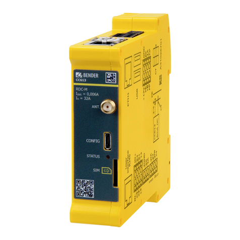
Bender CC613-H Series User manual

Manual ENCC613-Hxx_D00423_02_M_XXEN/11.2020
CC613-Hxx charge controller
Charge controller for wallboxes

2 CC613-Hxx_D00423_02_M_XXEN/11.2020
Service and support for Bender products
First-level support
Technical support
Carl-Benz-Strasse 8 • 35305 Grünberg • Germany
Telephone: +49 6401 807-760
0700BenderHelp *
Fax: +49 6401 807-629
E-mail: support@bender-service.de
Available on 365 days from 7.00 a.m. to 8.00 p.m. (MEZ/UTC +1)
* Landline German Telekom: Mon-Fri from 9.00 a.m. to 6 p.m.: 6.3 cents/30 sec.; remaining time: 6.3
cents/min.
Mobile phone: higher, depending on mobile phone tariff
Repair service
Repair, calibration and replacement service
Londorfer Strasse 65 • 35305 Grünberg • Germany
Telephone: +49 6401 807-780 (technical issues) or
+49 6401 807-784, -785 (commercial issues)
Fax: +49 6401 807-789
E-mail: [email protected]
Field service
On-site service
Telephone: +49 6401 807-752, -762 (technical issues) or
+49 6401 807-753 (commercial issues)
Fax: +49 6401 807-759
E-mail: fieldservice@bender-service.de
Mon-Thu 7.00 a.m. to 4.00 p.m., Fri 7.00 a.m. to 1 p.m. (MEZ/UTC +1)

CC613-Hxx_D00423_02_M_XXEN/11.2020 3
CC613-Hxx charge controller
Table of content
1 General instructions .........................................................................5
1.1 How to use this manual..............................................................................................5
1.2 Indication of important instructions and information ...................................5
1.2.1 Signs and symbols........................................................................................................5
1.3 Training courses and seminars.................................................................................5
1.4 Delivery conditions.......................................................................................................5
1.5 Inspection, transport and storage ..........................................................................5
1.6 Warranty and liability...................................................................................................6
1.7 Disposal of Bender devices........................................................................................6
1.8 Safety.................................................................................................................................6
2 Function...............................................................................................7
2.1 Intended use...................................................................................................................7
2.2 Product features (depending on the variant).....................................................7
2.3 Product description......................................................................................................7
2.4 Functional description ................................................................................................7
2.4.1 General functions (depending on the variant) ..................................................8
2.4.2 Load current and cooling control (temperature monitoring)......................8
3 Dimensions and mounting ..............................................................9
3.1 Dimensions......................................................................................................................9
3.2 Mounting..........................................................................................................................9
4 Connection ....................................................................................... 10
4.1 Connection conditions............................................................................................. 10
4.2 Connection type 2 plug...........................................................................................10
4.2.1 Charging system with permanently attached type 2 cable....................... 10
4.2.2 Charging system with type 2 socket-outlet.....................................................12
4.2.3 Connection locking actuators (depending on the variant)........................ 14
4.3 Connectivity.................................................................................................................15
4.3.1 USB configuration interface (CONFIG) ...............................................................15
4.3.2 Ethernet interface (depending on the variant)...............................................15
4.3.3 STATUS LED.................................................................................................................. 15
4.3.4 12 V power supply..................................................................................................... 15
4.3.5 Contactor connection...............................................................................................15
4.3.6 Weld check ...................................................................................................................15
4.3.7 Alternative connection switching contact contactor................................... 16
4.3.8 PE monitoring..............................................................................................................17
4.3.9 Control Pilot (CP) and Proximity Pilot connections (PP)..............................17
4.3.10 Emergency opener ....................................................................................................17
4.3.11 Residual direct current monitoring module (RDC-M)...................................17
4.3.12 Connectivity with Modbus meters (depending on the variant)...............17

4 CC613-Hxx_D00423_02_M_XXEN/11.2020
5 Configuration and testing............................................................. 19
5.1 Configuration...............................................................................................................19
5.1.1 Local configuration of parameters ......................................................................19
5.1.2 Factory settings...........................................................................................................20
5.1.3 Testing and system boot process ........................................................................20
5.1.3.1 Ethernet.....................................................................................................................................21
5.1.4 Plug locking and unlocking (depending on the variant)............................ 21
5.1.5 Charging........................................................................................................................21
6 Technical data.................................................................................. 22
6.1 Tabular data .................................................................................................................22
6.2 Ordering details..........................................................................................................25
6.3 Document revision history ..................................................................................... 26

CC613-Hxx_D00423_02_M_XXEN/11.2020 5
CC613-Hxx charge controller
1 General instructions
1.1 How to use this manual
This manual is intended for qualified personnel working in electrical engineering and electroics! Part
of the device documentation, in addition to this manual, is the enclosed "Safety instructions for
Bender products".
Read the manual before mounting, connecting and commissioning the device.
Always keep the manual within easy reach for future reference.
1.2 Indication of important instructions and information
I Danger! Indicates a high risk of danger that will result in death or serious injury if not avoided.
I Warning! Indicates a medium risk of danger that can lead to death or serious injury if not avoided.
I Caution! Indicates a low-level risk that can result in minor or moderate injury or damage to property if
not avoided.
i
Information can help to optimise the use of the product.
1.2.1 Signs and symbols
Disposal Temperature range Protect from dust
Protect from mois-
ture
Recycling RoHS directives
1.3 Training courses and seminars
www.bender.de > Know-how-> Seminars.
1.4 Delivery conditions
The conditions of sale and delivery set out by Bender apply. These can be obtained from Bender in printed or
electronic format.
The following applies to software products:
"Softwareklausel zur Überlassung von Standard- Software als Teil von Lieferungen, Ergänzung
und Änderung der Allgemeinen Lieferbedingungen für Erzeugnisse und Leistungen der
Elektroindustrie" (software clause in respect of the licensing of standard software as part of deliv-
eries, modifications and changes to general
delivery conditions for products and services in the electrical industry)
1.5 Inspection, transport and storage
Check the shipping and device packaging for transport damage and scope of delivery. The following must be
observed when storing the devices:
Die Elektroindustrie

6 CC613-Hxx_D00423_02_M_XXEN/11.2020
General instructions
1.6 Warranty and liability
Warranty and liability claims in the event of injury to persons or damage to property are excluded in case of:
Improper use of the device.
• Incorrect mounting, commissioning, operation and maintenance of the device.
• Failure to observe the instructions in this operating manual regarding transport, commissioning,
operation and maintenance of the device.
• Unauthorised changes to the device made by parties other than the manufacturer.
• Non-observance of technical data.
• Repairs carried out incorrectly
• Use of accessories and spare parts not recommended by Bender
• Catastrophes caused by external influences and force majeure.
• Mounting and installation with device combinations not recommended by the manufacturer.
This operating manual and the enclosed safety instructions must be observed by all persons working with the
device. Furthermore, the rules and regulations that apply for accident prevention at the place of use must be
observed.
1.7 Disposal of Bender devices
Abide by the national regulations and laws governing the disposal of this device.
For more information on the disposal of Bender devices, refer to
www.bender.de -> Service & support.
1.8 Safety
If the device is used outside the Federal Republic of Germany, the applicable local standards and regulations
must be complied with. In Europe, the European standard EN 50110 applies.
I Danger! Risk of electrocution due to electric shock! Touching live parts of the system carries the risk of:
• A fatal electric shock
• Damage to the electrical installation
• Destruction of the device
Before installing and connecting the device, make sure that the installation has been de-energised. The rules
for working on electrical systems must be observed.

CC613-Hxx_D00423_02_M_XXEN/11.2020 7
CC613-Hxx charge controller
2 Function
i
Local access to the charge controller
Local access to the charge controller is possible either as operator or as manufacturer. Further details are
described in chapter 5.1.1.
Operator access is possible via the http://192.168.123.123/operator:
- User name: operator
- Password: yellow_zone
The manufacturer can access the manufacturer area via the URL http://192.168.123.123/manufacturer:
- User name: manufacturer
- Password: orange_zone
i
The default passwords should be changed to prevent unauthorised access.
2.1 Intended use
The CC613-Hxx charge controller, hereinafter referred to as "charge controller", is the main component of a
charging system. It is intended for use in wallboxes installed in domestic environments. The CC613-HB variant
is designed for the use of a permanently attached cable and the CC613-HEM-X2 variant controls type 2 socket
outlets and permanently attached charging cables. The charge controller enables a setup that complies with
the requirements of current standards, e.g. IEC 61851-1 and IEC 62955.
2.2 Product features (depending on the variant)
• Charge controller in accordance with IEC 61851-1 (mode 3 charging)
• Residual direct current monitoring module (external RCD type A required), different cable lengths
can be selected
• Integrated emergency opener for actuator control (locking/unlocking) and monitoring of the 12 V
supply voltage
• Can be integrated in single- or three-phase systems up to 80 A
• 3 USB interfaces:
– 1 CONFIG interface for local configuration and installation of software updates
– 2 USB host interfaces
• Control Pilot and Proximity Pilot communication (acc. to IEC 61851-1)
• Internal temperature sensor to reduce the charging current depending on the ambient tempera-
ture
• ISO 15118 Powerline Communication (PLC) for plug & charge or autocharge
• Ethernet-interface
2.3 Product description
The charge controller is designed for use in compact wallboxes and primarily controls the charging process of
an electric vehicle. It monitors the internal hardware of the wallboxes.
Refer to "Ordering details" for product variants.
2.4 Functional description
The charging system consists of an RCD type A and a contactor. These are directly connected to a type 2 sock-
et-outlet, or to a permanently attached cable (see chapter "Charging system with type 2 socket- outlet").

8 CC613-Hxx_D00423_02_M_XXEN/11.2020
Function
2.4.1 General functions (depending on the variant)
• The charging system can be equipped with a meter. A Modbus meter is required for digital reading
of the energy consumption. The Modbus RTU wires are attached directly to the charge controller.
• A 12 V power supply is needed for operation.
• Power flow toward the vehicle is enabled by enabling the contactor via an integrated 230 V control
relay in the charge controller.
• For fault current detection in an AC charging system, the charge controller features an integrated
residual direct current monitoring module (RDC-M) which uses an externally connected current
transformer. With the integrated monitoring of the DC fault current, only an RCD type A is required
in the charging system.
• Data exchange between the electric vehicle and the charging system is possible via ISO 15118 com-
pliant Powerline Communication (PLC).
• Data management and control functionality of the charge controller:
– Termination of the charging process after tripping of the residual current device (RCD) due to a
residual current.
– Detection of critical fault currents by the RCM sensor. For the vehicle owner, this can be an early
warning, provided that the charge controller is connected to an energy management system
and that it supports this function.
i
The charge controller with residual direct current monitoring module (RDC-M) only works in combination
with the measuring current transformer (to be ordered separately).
I Caution! Risk of damage when pulling out the measuring current
transformer plug! If the measuring current transformer plug is pulled out
using too much force, the enclosure and the internal components may be
damaged. Use needle-nose pliers to unlock the measuring current transfor-
mer plug.
2.4.2 Load current and cooling control (temperature monitoring)
The charge controller is equipped with a temperature sensor, which allows the temperature in the environ-
ment of the charge controller to be estimated. Based on this estimation it is possible to dynamically reduce
the charging current or even suspend charging. This feature can serve to maintain the temperature inside the
enclosure within the permissible range for the components used in a charging system. Two temperature
thresholds for charging current reduction and charging interruption can be set via the Manufacturer tab.
i
The actual temperature is affected by heat generated by the controller itself.

CC613-Hxx_D00423_02_M_XXEN/11.2020 9
CC613-Hxx charge controller
3 Dimensions and mounting
3.1 Dimensions
Abb. 3–1 Note: Dimensions in mm acc. to ISO 2768 - m
* Dimensions incl. antenna socket (depending on the variant)
3.2 Mounting
i
DIN rail mounting
Lateral distance to other equipment: 6 mm (self-heating)
In horizontal mounting position the max. operating temperature is reduced by 15 °C (refer to "Other" in the
technical data).
111 (112,3*)
23,5
99
2.
Click!
3.
1.

10 CC613-Hxx_D00423_02_M_XXEN/11.2020
Connection
4 Connection
4.1 Connection conditions
I risk of electric shock! Parts of the system may be live (charge controller terminals up to 230 V, charging
station 400 V). Before touching parts of the system, ensure that it has been de-energised.
I Caution! Risk of injury from sharp-edged terminals! Handle enclosure and terminals with care.
i
Information:
• PE is connected to "0V"; reference level for Control Pilot (CP communication) must be at the same
level as the power supply (IEC 61851 series of standards).
• Lay cables only inside the wallbox and not in parallel with power cables.
• Cable lengths (except Modbus, Ethernet, Power IN and charging cable): < 3 m.
• Maximum cable length Ethernet: 100 m.
• Maximum cable length Modbus: 250 m.
• The Ethernet shield is directly connected to PE.
• External Modbus must be terminated by the customer with a terminating resistor of 120 Ω.
i
For further information on connection, refer to the manuals of the accessories (e.g. W15BS).
4.2 Connection type 2 plug
4.2.1 Charging system with permanently attached type 2 cable
L1
L1
L3
NPE
L2/N
L1
CS CP
PE
PP
CP
PE
L1 N
L3
L2
L2
N
PE

CC613-Hxx_D00423_02_M_XXEN/11.2020 11
CC613-Hxx charge controller

12 CC613-Hxx_D00423_02_M_XXEN/11.2020
Connection
4.2.2 Charging system with type 2 socket-outlet
Wiring diagram
top front bottom
N
L3
L2
L1
PE
J
M
–
+
q
CP
PP
PE
NL1
L2
L3
PE
0V
CP
B Mod.
PP
PE
+12V
A Mod.
D
B
A
C
J
H
F
L
H
WA
24
WB
23
B
B
HS2
A
HS1
AC
DC
0 V
12 V
n
p
H
V
m
o
12
CT
0V
PE
B Modbus
CP
+12V
PE
A Mod.
PP
WA
Relais 23
WB
Relais 24
230V only
Opto1 In-
Motor A
Motor HS1
Relais 13
Opto1 In+
Motor B
Motor HS2
Relais 14
GND2 Modbus
B2 Modbus
A2 Modbus
User
interface
RJ45
ETH1
10/100 Mbit
USB
Host
Side view from right

CC613-Hxx_D00423_02_M_XXEN/11.2020 13
CC613-Hxx charge controller
Legend
A Connection measuring current transformer (CT) mRCD type A
B 12 V supply, PE, Modbus meter, CP, PP nVoltage supply DC 12V
C 2x USB type A (depending on the variant) oMeasuring current transformer (CT)
with plug
D Connection Ethernet (depending on the variant) pContactor
F Conguration interface qType 2 socket-outlet
H Weld check, relay for contactor control rated for 230V/4 A
J Locking (depending on the variant)
L STATUS LED
Terminal assignment
B
0V Input 0V
+ 12V Supply voltage +12V
PE Input PE
PE Input PE
B Mod. Modbus meter B
J
A Mod. Modbus meter A
CP Control Pilot A Actuator A: Locking actuator output negative
PP Proximity Pilot B Actuator B: Locking actuator output positive
HS2 Actuator HS2: Locking input actuator switch
H
WA Weld check input L1 HS1 Actuator HS1: Locking 12V output actuator switch
23 Relay 23: Switching contact
contactor
WB Weld check input N
24 Relay 24: Switching contact
contactor
I Caution! Switching contact contactor and weld check at terminal H are only suitable for mains voltage
(230 V)!
Not permitted for SELV/PELV voltages.
i
For variants with a permanently attached charging cable, the terminals J for plug locking and the wiring of
the Proximity Pilot (PP) to terminal B are not required.

14 CC613-Hxx_D00423_02_M_XXEN/11.2020
Connection
4.2.3 Connection locking actuators (depending on the variant)
Type 2 socket-outlet (actuator type) Actua-
tor
A HS1 B HS2
Socket-outlet actuator wiring
• Mennekes (31016, 31023, 31024, 31038)
• Bals (801191-801195, 80300, 9743205000,
9743211000)
• Walther Werke (9743211000)
• Harting
Hella
Wire 3
(///)
Wire 1
(/)
Wire 2
(//)
• Walther Werke Eco Slim 32 A (9743205180)
with connection cable (790000001)
Wire 3
(black)
Wire 1
(blue)
Wire 2
(red)
• Phoenix Contact (1624129) Küster BU/BN BU/YE BU/RD BU/GN
Example Hella actuator:
Example Küster:
M
CP
PP
PE
NL1
L2
L3
B
HS2
A
HS1
M
CP
PP
PE
NL1
L2
L3
In+
B
14
HS2
In-
A
13
HS1
BU/YE
BU/RD
BU/BN
BU/GN

CC613-Hxx_D00423_02_M_XXEN/11.2020 15
CC613-Hxx charge controller
4.3 Connectivity
4.3.1 USB configuration interface (CONFIG)
The USB configuration interface (CONFIG) on the front panel of the charge controller is connected to a con-
ventional laptop, PC or tablet computer via a micro USB cable. This interface allows local configuration of the
charge controller. In addition, it enables the installation of software updates (for a configuration description,
refer to chapter "Configuration and testing"). The web interface can be accessed via the IP address
192.168.123.123.
4.3.2 Ethernet interface (depending on the variant)
The charge controller can be connected to an existing Ethernet network via an Ethernet interface. For further
information, refer to chapter "Configuration and testing".
4.3.3 STATUS LED
The "STATUS" LED on the front panel indicates the following system states:
Power on/system not ready for operation
System is starting
System started, not ready for operation yet
System ready for operation
System error
4.3.4 12 V power supply (depending on the variant)
The charge controller is supplied with power from a 12 V main voltage source at the +12 V and 0V connec-
tions.
4.3.5 Contactor connection
The charge controller controls the contactor, which in turn controls the power flow toward the vehicle. The
contactor is controlled via a relay in the charge controller, the contacts of which are rated for 230 V/4 A.
4.3.6 Weld check
By means of the measuring lines WA/WB (terminal designation) an impermissible closing of the contactor con-
tacts, e.g. welding/sticking, can be detected.

16 CC613-Hxx_D00423_02_M_XXEN/11.2020
Connection
Wiring diagram
I risk of a short circuit! According to DIN VDE 0100-430, devices for protection against a short circuit can be
omitted for the coupling of terminals WA and WB if the wiring is carried out in such a manner as to reduce
the risk of a short circuit to a minimum. (A short-circuit-proof and earth-fault-proof wiring is recommen-
ded). The connecting lines WA and WB to the system to be monitored must be designed as spur lines. No
load current may be conducted through the terminals.
4.3.7 Alternative connection switching contact contactor
Detail of wiring diagram chapter "Charging system with type 2 socket outlet"
The control voltage of the contactor can alternatively be supplied directly via a common fuse of the 12-V
power supply. For this purpose, the fuse must be selected accordingly.
I Caution: DC fault currents, caused by the contactor or the control relay, are not detected.
H
WA
24
WB
23
CP
PP
PE
NL1
L2
L3
L1L2L3N
PE
D
B
A
C
H
WA
24
WB
23
AC
DC
0 V
12 V
n
p
H
V
m
o

CC613-Hxx_D00423_02_M_XXEN/11.2020 17
CC613-Hxx charge controller
4.3.8 PE monitoring
The PE monitoring checks whether there is a connection from the CC613 to PE. For this purpose, L1 must be
connected to WA. The cable length is limited by its capacitance per unit length.
I Pe monitoring does not replace tests (example: protective conductor resistance).
I the Ethernet shield and the USB shield are directly connected to PE. This must be taken into account in
the test!
I hV test: WA is coupled to PE via a protective circuit and with approximately 140 kΩ. Above 500 V, a
leakage current flows to PE. Test voltages above AC 1000 V/1 sec. are not permissible!
4.3.9 Control Pilot (CP) and Proximity Pilot connections (PP)
The Control Pilot (CP) and Proximity Pilot (PP) contacts connect the charge controller to the socket-outlet, en-
abling it to communicate with the vehicle and the cable plug. The PP contact detects the presence of the plug
and the CP contact exchanges control signals between the electric vehicle and the charging station (see IEC
61851).
i
PP is not required if the charging cable is permanently attached.
4.3.10 Emergency opener
The emergency opener is integrated as a circuit group in the charge controller. In the event of a power failure,
the plug of the charging cable is automatically unlocked so that it can be removed
4.3.11 Residual direct current monitoring module (RDC-M)
For residual current detection in an AC charging system, an integrated residual direct current monitoring
module (RDC-M) is used. This module uses an external magnetically shielded measuring current transformer.
This allows the use of a residual current device (RCD) type A instead of an RCD type B. The relay in the charge
controller is de-energised if, during the charging process, a fault current
IΔn ≥ DC 6 mA flows.
4.3.12 Connectivity with Modbus meters (depending on the variant)
The use of a meter is not mandatory. It is necessary if measured values are required during normal operation.
The meter is connected to the Modbus meter interface (terminal B) of the charge controller. Various Modbus
meters are currently supported, including:
• ABB B23 series
• B-Control EM300-LR/EM300-LR (TCP)
• Carlo Gavazzi EM200/EM340
• Eastron SDM120/SDM220/ SDM630 series
• Finder
• Garo EM270/GNM1D/GNM3D/GNM3T/GM3T
• IME CE4DMID31

18 CC613-Hxx_D00423_02_M_XXEN/11.2020
Connection
• inepro PRO1/PRO2/PRO380
• NZR EcoCount S85
• Optec
• Phoenix Contact EEM-MB371 (TCP)
• Saia ALE3
• Siemens 7KT1666/7KM2200 (TCP)
Meter Slave ID Baud rate Parity Data Bit Stop Bit
1 9600 N (none) (except Saia) -> even 8 1
Additional Modbus meters can be included in future software updates upon customer request. Refer to the
Manufacturer tab on the web server for a list of supported Modbus meters.
The Modbus meter interface is terminated with a terminating resistor of 120 Ω.
i
With use of a Modbus TCP meter it is possible to read the energy demand of external consumers (e.g. resi-
dential buildings). Depending on this, the maximum charge current can be set.

CC613-Hxx_D00423_02_M_XXEN/11.2020 19
CC613-Hxx charge controller
5 Configuration and testing
5.1 Configuration
The following options are available for configuring the charging system:
Access to web interface via the following interfaces:
• Micro USB configuration interface (CONFIG)
• Ethernet interface
5.1.1 Local configuration of parameters
In order to locally configure the charging system via the charge controller, it is necessary to connect a micro
USB cable to a laptop, PC or tablet computer with a standard USB host interface. Once connected, the charge
controller is recognised as a USB network adapter.
i
The USB configuration interface (CONFIG) emulates a Remote Network Driver Interface Specification
(RNDIS) network when it is connected to a Windows, Linux or Mac computer. For Windows 10 and higher,
Linux and Mac operating systems, this virtual network is automatically detected. No driver is required.
On a Windows host device with a different Windows operating system the driver for the RNDIS network
adapter must be manually selected:
• Open the device manager on the control panel.
• Right click the "RNDIS/Ethernet Gadget" menu item located at "Other devices" and select "Update
driver software".
• Select the option "Browse my computer for driver software".
• Then click on the option "Select from a list of device drivers on my computer".
• Select the category "Network adapters" from the list.
• In the window that appears, select the manufacturer "Microsoft Corporation" and the network
adapter "Remote NDIS Compatible Device". The device driver is then installed and the system rec-
ognises the charge controller as a network adapter.
The web interface for configuration can be accessed with an ordinary browser. The charge controller uses the
local IP address 192.168.123.123 with the subnet mask 255.255.255.0 via the configuration interface. The con-
nected device automatically receives a corresponding IP address via the Dynamic Host Configuration Protocol
(DHCP) after the connection has been established. The communication with the charging system is based on
this IP address.
Each parameter is adequately described on the respective web interface tab. For further information on the
parameters, refer to the State, Operator and Manufacturer tabs.
The State tab of the charging system control interface can be accessed via the URL http://192.168.123.123. It
only provides status information.
Besides displaying status information, parameters of the Operator and Manufacturer tab can be set:
The Operator tab of the charging system control interface can be accessed via the URL
http://192.168.123.123/operator. To access this tab, user name and password are required:
• User name: operator
• Password: yellow_zone

20 CC613-Hxx_D00423_02_M_XXEN/11.2020
Configuration and testing
The Manufacturer tab of the charging system control interface can be accessed via the URL
http://192.168.123.123/manufacturer. To access this tab, user name and password are required:
• User name: manufacturer
• Password: orange_zone
i
The default passwords should be changed to prevent unauthorised access.
The manufacturer can also change the user passwords and parameters via the Operator tab.
Application of changed parameters
Parameter changes are not necessarily applied after submission. To submit all changed parameters, click the
"Save & Restart" button at the bottom of the tab. A message indicating a necessary restart may appear.
I automatiC reboot of the charge controller! In order to ensure perfect functionality, the charge controller
carries out a regular system reboot.
i
After the web configuration interface has been accessed or while a vehicle is connected, the charging point
will suppress system reboots for at least 2 minutes to allow all parameters to be configured.
5.1.2 Factory settings
i
Resetting to factory settings deletes all settings except the serial number.
Click the "Operator Default & Restart" button on
the Operator tab to reset changed parameters
of the operator configuration to default.
Click the "Settings Default & Restart" button on
the Settings tab to reset changed parameters to
default.
Click the "Manufacturer Default & Restart" button on the Manufacturer tab to reset changed parameters of
the manufacturer configuration to default. Click the "Factory Reset & Restart" button to reset the charge con-
troller to factory settings.
5.1.3 Testing and system boot process
After completing the configuration, the charge controller must be tested for operability. This can be done us-
ing a vehicle simulator. The following is checked:
• Successful boot process
• Connection to meter possible (meter configuration)
• Plug locking and unlocking works (depending on the variant)
This manual suits for next models
2
Table of contents
Other Bender Controllers manuals
Bender
Bender ISOMETER isoMIL425HV User manual
Bender
Bender CC612 User manual
Bender
Bender CC612 EV User manual

Bender
Bender CC611 User manual
Bender
Bender PRC470 Series User manual
Bender
Bender ICC1324 User manual
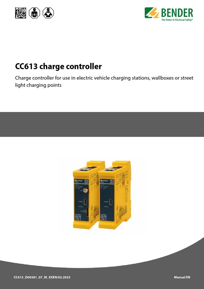
Bender
Bender CC613 User manual

Bender
Bender CC612 User manual
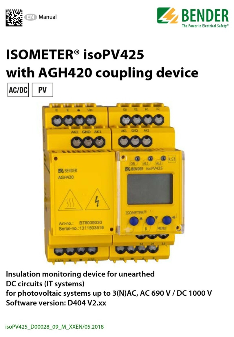
Bender
Bender ISOMETER isoPV425 with AGH420 User manual
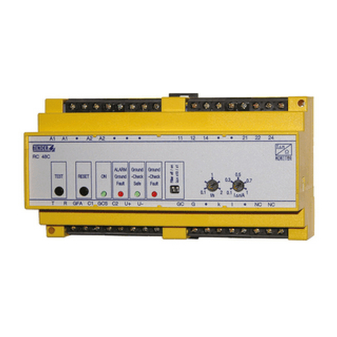
Bender
Bender RC48C User manual

