Fluke Biomedical ESA614 Parts list manual

PN 5006602
August 2018, Rev. 1
© 2018 Fluke Corporation. All rights reserved. Specifications are subject to change without notice.
All product names are trademarks of their respective companies.
ESA614
Electrical Safety Analyzer
Getting Started Manual

Warranty and Product Support
Fluke Biomedical warrants this instrument against defects in materials and workmanship for one year from the date of
original purchase OR two years if at the end of your first year you send the instrument to a Fluke Biomedical service center
for calibration. You will be charged our customary fee for such calibration. During the warranty period, we will repair or at our
option replace, at no charge, a product that proves to be defective, provided you return the product, shipping prepaid, to
Fluke Biomedical. This warranty covers the original purchaser only and is not transferable. The warranty does not apply if the
product has been damaged by accident or misuse or has been serviced or modified by anyone other than an authorized
Fluke Biomedical service facility. NO OTHER WARRANTIES, SUCH AS FITNESS FOR A PARTICULAR PURPOSE, ARE
EXPRESSED OR IMPLIED. FLUKE SHALL NOT BE LIABLE FOR ANY SPECIAL, INDIRECT, INCIDENTAL OR
CONSEQUENTIAL DAMAGES OR LOSSES, INCLUDING LOSS OF DATA, ARISING FROM ANY CAUSE OR THEORY.
This warranty covers only serialized products and their accessory items that bear a distinct serial number tag. Recalibration
of instruments is not covered under the warranty.
This warranty gives you specific legal rights and you may also have other rights that vary in different jurisdictions. Since
some jurisdictions do not allow the exclusion or limitation of an implied warranty or of incidental or consequential damages,
this limitation of liability may not apply to you. If any provision of this warranty is held invalid or unenforceable by a court or
other decision-maker of competent jurisdiction, such holding will not affect the validity or enforceability of any other provision.
7/07

Notices
All Rights Reserved
Copyright 2018, Fluke Biomedical. No part of this publication may be reproduced, transmitted, transcribed, stored in a retrieval system, or
translated into any language without the written permission of Fluke Biomedical.
Copyright Release
Fluke Biomedical agrees to a limited copyright release that allows you to reproduce manuals and other printed materials for use in service
training programs and other technical publications. If you would like other reproductions or distributions, submit a written request to
Fluke Biomedical.
Unpacking and Inspection
Follow standard receiving practices upon receipt of the instrument. Check the shipping carton for damage. If damage is found, stop unpacking
the instrument. Notify the carrier and ask for an agent to be present while the instrument is unpacked. There are no special unpacking
instructions, but be careful not to damage the instrument when unpacking it. Inspect the instrument for physical damage such as bent or
broken parts, dents, or scratches.
Technical Support
For application support or answers to technical questions, either email techservices@flukebiomedical.com or call 1-800- 850-4608 or
1-440-248-9300. In Europe, email techsupport.emea@flukebiomedical.com or call +31-40-2965314.
ClaimsOur routine method of shipment is via common carrier, FOB origin. Upon delivery, if physical damage is found, retain all packing materials in
their original condition and contact the carrier immediately to file a claim. If the instrument is delivered in good physical condition but does not
operate within specifications, or if there are any other problems not caused by shipping damage, please contact Fluke Biomedical or your local
sales representative.
Returns and Repairs
Return Procedure
All items being returned (including all warranty-claim shipments) must be sent freight-prepaid to our factory location. When you return an
instrument to Fluke Biomedical, we recommend using United Parcel Service, Federal Express, or Air Parcel Post. We also recommend that
you insure your shipment for its actual replacement cost. Fluke Biomedical will not be responsible for lost shipments or instruments that are
received in damaged condition due to improper packaging or handling.
Use the original carton and packaging material for shipment. If they are not available, we recommend the following guide for repackaging:
Use a double–walled carton of sufficient strength for the weight being shipped.
Use heavy paper or cardboard to protect all instrument surfaces. Use nonabrasive material around all projecting parts.
Use at least four inches of tightly packed, industry-approved, shock-absorbent material around the instrument.

Returns for partial refund/credit:
Every product returned for refund/credit must be accompanied by a Return Material Authorization (RMA) number, obtained from our Order
Entry Group at 1-440-498-2560.
Repair and calibration:
To find the nearest service center, go to www.flukebiomedical.com/service or
In the U.S.A. and Asia:
Cleveland Calibration Lab
Tel: 1-800-850-4608 x2564
In Europe, Middle East, and Africa:
Eindhoven Calibration Lab
Tel: +31-40-2675300
To ensure the accuracy of the Product is maintained at a high level, Fluke Biomedical recommends the product be calibrated at least
once every 12 months. Calibration must be done by qualified personnel. Contact your local Fluke Biomedical representative for
calibration.
Certification
This instrument was thoroughly tested and inspected. It was found to meet Fluke Biomedical’s manufacturing specifications when it was
shipped from the factory. Calibration measurements are traceable to the National Institute of Standards and Technology (NIST). Devices for
which there are no NIST calibration standards are measured against in-house performance standards using accepted test procedures.
WARNING
Unauthorized user modifications or application beyond the published specifications may result in electrical shock hazards or improper
operation. Fluke Biomedical will not be responsible for any injuries sustained due to unauthorized equipment modifications.
Restrictions and Liabilities
Information in this document is subject to change and does not represent a commitment by Fluke Biomedical. Changes made to the
information in this document will be incorporated in new editions of the publication. No responsibility is assumed by Fluke Biomedical
for the use or reliability of software or equipment that is not supplied by Fluke Biomedical, or by its affiliated dealers.
Manufacturing Location
The ESA614 Electrical Safety Analyzer is manufactured at Fluke Biomedical, 6920 Seaway Blvd., Everett, WA, U.S.A.

i
Table of Contents
Title Page
Introduction .................................................................................................................... 1
Intended Use.................................................................................................................. 3
Safety Information .......................................................................................................... 3
Unpack the Product........................................................................................................ 5
Instrument Familiarization .............................................................................................. 6
How to Hold the Product ................................................................................................ 10
Connect to Line Power................................................................................................... 10
Connect a DUT to the Product ....................................................................................... 11
Turn On the Product....................................................................................................... 11
How to Set the Display Contrast................................................................................ 11
How to Set the Language.......................................................................................... 12
For More Information...................................................................................................... 14
Maintenance................................................................................................................... 14
Fuse Test and Fuse Replacement............................................................................. 14
How to Clean the Product.......................................................................................... 15

ESA614
Getting Started Manual
ii
Replaceable Parts ......................................................................................................... 16
Accessories ................................................................................................................... 17
Specifications ................................................................................................................ 18
Detailed Specifications .................................................................................................. 20

1
Electrical Safety Analyzer
Introduction
XW Warning
To prevent possible electrical shock, fire, or
personal injury, read all safety information
before you use the Product.
The Fluke Biomedical ESA614 Electrical Safety Analyzer
(the Product) is a full-featured, compact, portable
analyzer, designed to verify the electrical safety of medical
devices. The Product tests to domestic (ANSI/AAMI ES1,
NFPA 99) electrical safety standards. The Product
simulates ECG to do performance tests on ECG monitors.
The Product does these tests:
•Line voltage
•Ground Wire resistance
•Equipment current
•Insulation resistance
•Ground leakage
•Chassis leakage
•Lead to Ground and Lead to Lead leakage
•Lead isolation

ESA614
Getting Started Manual
2
•Point to point leakage, voltage, and resistance
•ECG simulation and performance waveforms
Table 1 is a list of the symbols used on the Product and in
this manual.
Table 1. Symbols
Symbol Description
WWARNING. RISK OF DANGER.
XWARNING. HAZARDOUS VOLTAGE.
Risk of electric shock.
Consult user documentation.
Fuse
˜Equipotential
Measurement Category II is applicable to
test and measuring circuits connected
directly to utilization points (socket
outlets and similar points) of the low-
voltage MAINS installation.
Symbol Description
PConforms to European Union directives.
)Certified by CSA Group to North
American safety standards.
Conforms to relevant Australian EMC
requirements.
Conforms to relevant South Korean EMC
Standards.
~
This product complies with the WEEE
Directive marking requirements. The
affixed label indicates that you must not
discard this electrical/electronic product
in domestic household waste. Product
Category: With reference to the
equipment types in the WEEE Directive
Annex I, this product is classed as
category 9 "Monitoring and Control
Instrumentation" product. Do not dispose
of this product as unsorted municipal
waste.

Electrical Safety Analyzer
Intended Use
3
Intended Use
The Product is an electronic signal source and
measurement device for verifying the electrical safety of
medical devices. The Product also provides ECG
simulation and performance waveforms to verify patient
monitors are performing within their operating
specifications.
The Product provides the following function categories:
•ECG Functions
•ECG-Performance Testing
The intended user is a trained biomedical equipment
technician who performs periodic preventative
maintenance checks on patient monitors in service. Users
can be associated with hospitals, clinics, original
equipment manufacturers and independent service
companies that repair and service medical equipment. The
end user is an individual, trained in medical
instrumentation technology.
This Product is intended to be used in the laboratory
environment, outside of the patient care area, and is not
intended for use on patients, or to test devices while
connected to patients. This Product is not intended to be
used to calibrate medical equipment. It is intended for over
the counter use.
Safety Information
In this manual, a Warning identifies conditions and
procedures that are dangerous to the user. A Caution
identifies conditions and procedures that can cause
damage to the Product or the equipment under test.
XW Warning
To prevent possible electrical shock, fire, or
personal injury, follow these guidelines:
•Carefully read all instructions.
•Use the Product only as specified, or the
protection supplied by the Product can
be compromised.
•Use only the mains power cord and
connector approved for the voltage and
plug configuration in your country and
rated for the Product.
•Do not apply more than the rated voltage,
between the terminals or between each
terminal and earth ground.
•Measure a known voltage first to make
sure that the Product operates correctly.

ESA614
Getting Started Manual
4
•Do not touch voltages >30 V ac rms, 42 V
ac peak, or 60 V dc.
•Do not use the Product around explosive
gas, vapor, or in damp or wet
environments.
•Do not use an extension cord or adapter
plug.
•Do not connect the Product to a patient or
equipment connected to a patient. The
Product is intended for equipment
evaluation only. The Product must not be
used in diagnostics, treatment, or other
capacities where the Product could touch
a patient.
•Remove the null post adapter from the
∅/Null jack after a test lead zero is
performed. The ∅/Null jack becomes
potentially hazardous during some of the
test conditions. Use only cables with
correct voltage ratings.
•Keep fingers behind the finger guards on
the probes.
•Do not use the 15-20 A adapter to supply
power to devices rated more than 15 A.
This can overload the installation.
•Use only current probes, test leads, and
adapters supplied with the Product.
•Comply with local and national safety
codes. Use personal protective
equipment (approved rubber gloves, face
protection, and flame-resistant clothes) to
prevent shock and arc blast injury where
hazardous live conductors are exposed.
•Do not touch metal parts of the device
under test (DUT) while you do a test.
Some tests apply high voltage and high
current to the DUT with the DUT earth
connection open or closed.
•Examine the case before you use the
Product. Look for cracks or missing
plastic. Carefully look at the insulation
around the terminals.
•Do not use test leads if they are
damaged. Examine the test leads for
damaged insulation, exposed metal, or if
the wear indicator shows. Check test lead
continuity.

Electrical Safety Analyzer
Unpack the Product
5
•Make sure the ground conductor in the
mains power cord is connected to a
protective earth ground. Disruption of the
protective earth could put voltage on the
chassis that could cause death.
•Replace the mains power cord if the
insulation is damaged or if the insulation
shows signs of wear.
•Connect the common test lead before the
live test lead and remove the live test lead
before the common test lead.
•Remove all probes, test leads, and
accessories that are not necessary for
the measurement.
•Disable the Product if it is damaged.
•Do not use the Product if it is damaged.
•Do not use the Product if it operates
incorrectly.
•Use this Product indoors only.
•Use Product-approved measurement
category (CAT), voltage, and amperage
rated accessories (probes, test leads, and
adapters) for all measurements.
•Do not put metal objects into connectors.
•Do not use exposed metal BNC or banana
plug connectors Limit operation to the
specified measurement category, voltage,
or amperage ratings.
•Only use probes, test leads, and
accessories that have the same
measurement category, voltage, and
amperage ratings as the Product.
Unpack the Product
Carefully unpack all items from the box and check that you
have these items:
•ESA614
•Getting Started Manual
•Carrying Case
•Power Cord
•ESA USA Accessory Kit
•Ansur Demo CD
•Null Post Adapter
•5-to-5 Banana to ECG Adapter (BJ2ECG)
•USB Transfer Cable

ESA614
Getting Started Manual
6
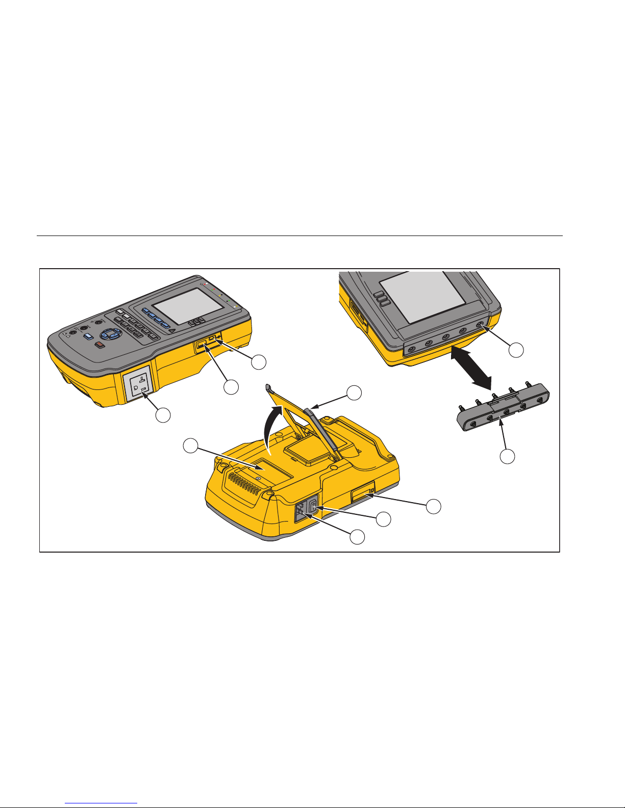
Instrument Familiarization
Figure 1 and Table 0-2 show the front-panel controls and connections of the Product.
2
3
7
8
9
1
4
5
6
gtv116.eps
Figure 1. Front-Panel Controls and Connections

Electrical Safety Analyzer
Instrument Familiarization
7
Table 2. Top-Panel Controls and Connections
Item Name Description
Equipment Outlet
Configuration Buttons Controls the configuration of the equipment outlet. Opens and closes the neutral and
ground connection and reverses the polarity of the neutral and hot connection.
High Voltage Indicator Illuminates when high voltage is applied to the ECG/Applied Parts posts RED V/e/A
jack or the Test Receptacle.
Test Function Buttons Selects the Product test functions.
Navigation Buttons Cursor control buttons for navigating menus and lists.
Test Button Starts selected tests.
Enter Button Sets the highlighted function.
Input Jacks Test lead connectors.
Nulling Jack Connection to zero test lead resistance.
Function Softkeys Keys F1 through F4 are used to select from a number of selections that show in the
LCD above each function softkey.
ESA614
Getting Started Manual
8
Figure 2 and Table 3 describe the side and top-panel connections of the Product.
RA LLLA RLV1
RFLNC1
3
2
9
10
1
8
7
6
4
5
gtv110.eps
Figure 2. Side and Top-Panel Connections

Electrical Safety Analyzer
Instrument Familiarization
9
Table 3. Side and Top-Panel Connections
Item Name Description
Equipment Outlet Equipment outlet, specified to the version of the Product, which supplies a DUT
connection.
USB A Controller Port For external keyboard, barcode reader, or printer.
USB Device Port
(Mini B-style connector) Digital connection to control the Product from a PC or instrument controller.
Fuse Access Door Equipment outlet fuse access.
Tilt Stand Holds the Product in a tilted position.
SD Card Slot SD Memory Card access.
AC Power Switch Turns ac power on and off.
Power Input Connector A grounded male three-prong (IEC 60320 C19) connector that accepts the
line-power cord.
ECG/Applied Parts Jacks Connection posts for Device Under Test (DUT) applied parts, such as ECG
leads. Used to test for leakage current through leads and to supply ECG
signals and performance waveforms to a DUT.
Banana Jack to ECG Adapter Adapter to connect ECG snap leads to the Product.
ESA614
Getting Started Manual
10
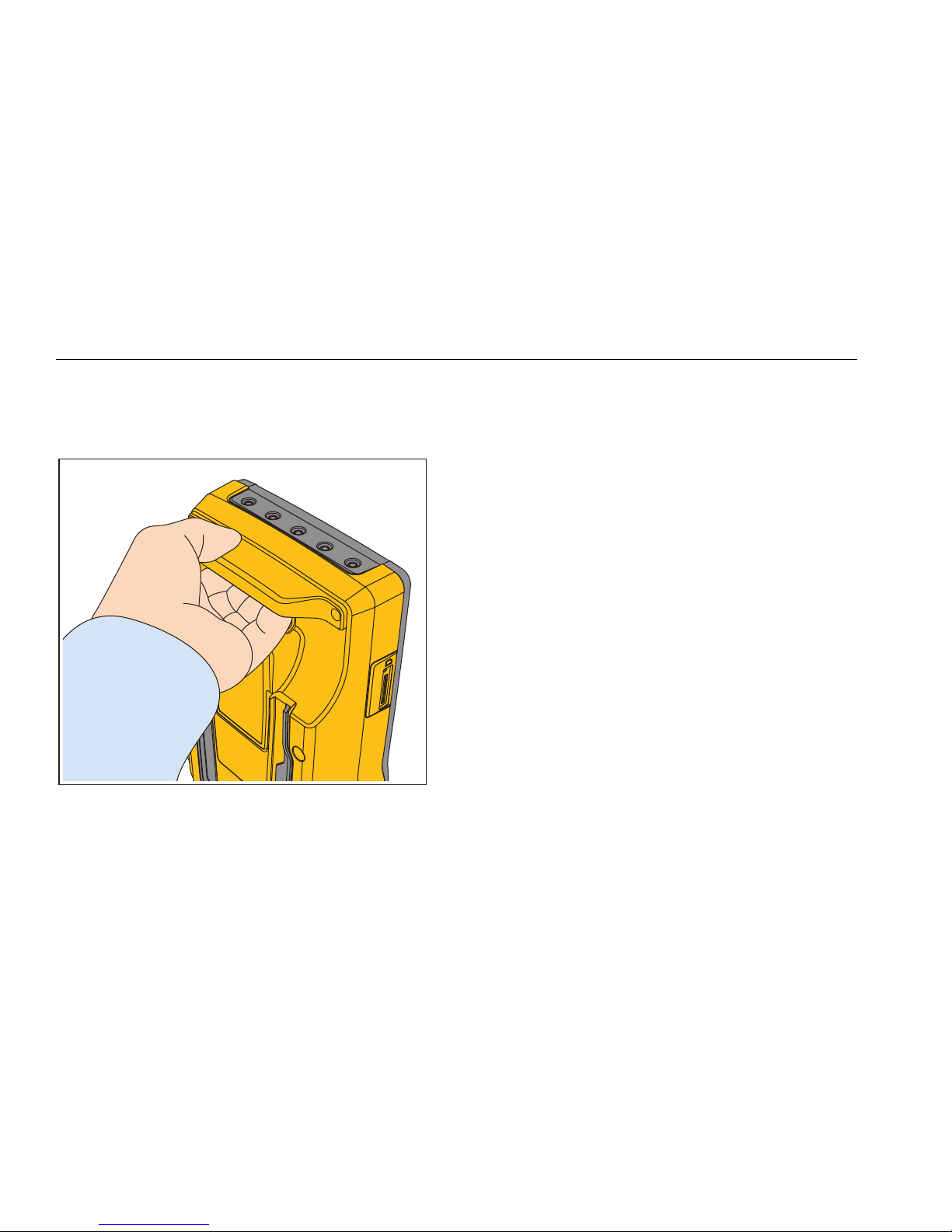
How to Hold the Product
When you move the Product, use the handle on the
bottom case to hold it. See Figure 3.
gtv122.eps
Figure 3. Product Handle
Connect to Line Power
XWWarning
To prevent possible electrical shock, fire, or
personal injury:
•Do not use an extension cord or adapter
plug.
•Make sure the ground conductor in the
mains power cord is connected to a
protective earth ground. Disruption of
the protective earth could put voltage on
the chassis that could cause death.
•Replace the mains power cord if the
insulation is damaged or if the insulation
shows signs of wear.
•Use only the mains power cord and
connector approved for the voltage and
plug configuration in your country and
rated for the Product.
•Do not put the Product where access to
the mains power cord is blocked.

Electrical Safety Analyzer
Connect a DUT to the Product
11
The Product is intended for use with single-phase,
grounded power. It is not intended for dual, split-phase or
three-phase power configurations. It can be used with a
power system that supplies the correct voltages for
single-phase and is grounded, or is an isolated power
system.
Use the power cord for your country mains supply that is
not more than the voltage or power rating of the product.
Connect the cord into the power input connector and then
to the mains outlet.
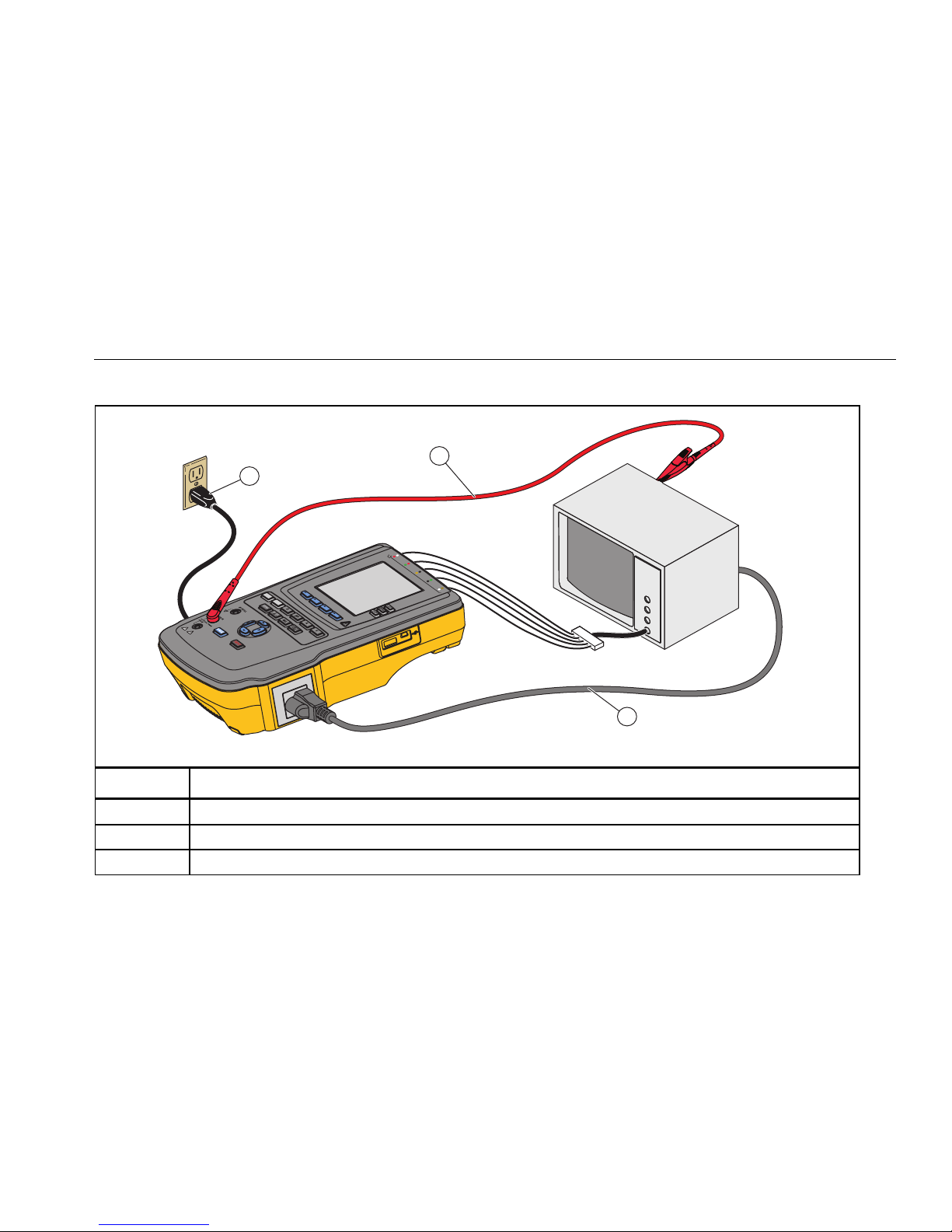
Connect a DUT to the Product
You can connect a Device Under Test (DUT) a number of
different ways for a full electrical safety test. Table 4
shows a DUT connected to the test receptacle, applied
parts posts, and a connection to the enclosure or
protective earth ground of the DUT.
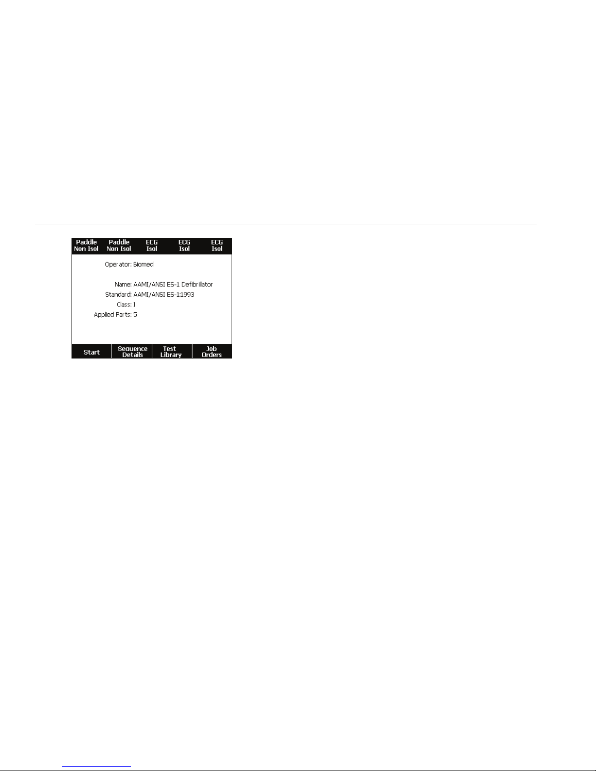
Turn On the Product
Note
To make sure the high-voltage indicator works,
look for it to illuminate at power-up.
Push the power switch so the “I” side of the switch is
down. The Product does a series of self-tests and then
shows the message in Figure 4 when the self-test
completes.
How to Set the Display Contrast
There are two procedures to set the display contrast.
From the Test Sequence start-up menu or through the
Setup menu.
When the Product shows the start-up menu shown in
Figure 4, push or to increase or decrease the
display contrast respectively. Push the Done softkey to
exit contrast setup.
ESA614
Getting Started Manual
12
gtv128.eps
Figure 4. Product Ready for Operation
To adjust the contrast through the Setup menu:
1. From the Setup menu, push the Instrument Setup
softkey.
2. Push the Display Contrast softkey.
3. Push or to increase or decrease the display
contrast respectively.
4. Push the Done softkey to exit contrast setup.
How to Set the Language
The Product can show data in English, French, German,
Spanish, Italian, or Portuguese. To change the language:
1. Push .
2. From the Setup menu, push the Instrument Setup
softkey.
3. Push or until the Language variable is
highlighted.
4. Push .
5. Push or to highlight one of the languages.
6. Push .
Electrical Safety Analyzer
Turn On the Product
13
Table 4. DUT Connections to the Product
RALL LARLV1
RFLNC
1
1
2
3
gtv113.eps
Item Description
Connect the ESA614 to grounded mains socket.
To protective earth or any exposed conductive surface on the enclosure.
Connect the DUT ac power cord to the equipment outlet on the Analyzer.

ESA614
Getting Started Manual
14
For More Information
For more information on how to use the Product, refer to
the ESA614 Users Manual at www.flukebiomedical.com.
Maintenance
XW Warning
To prevent possible electrical shock, fire, or
personal injury:
•Turn off the Product and remove the
mains power cord. Stop for 2 minutes to
let the internal circuits discharge before
you open the fuse door or remove
Product covers.
•Do not operate the Product with covers
removed or the case open. Hazardous
voltage exposure is possible.
•Disconnect the mains power cord before
you remove the Product covers.
•Remove the input signals before you
clean the Product.
•Use only specified replacement parts.
•Use only specified replacement fuses.
•Have an approved technician repair the
Product.
The Product is a calibrated measurement instrument. Use
the necessary precautions to prevent mechanical abuse
that could change the calibrated adjustments.
Fuse Test and Fuse Replacement
XW Warning
To prevent electric shock, remove all power
cords and test leads from the Product before
opening the fuse door.
For electrical protection of the equipment outlet, the
Product uses two fuses, one in the live (L1) line and one
in the neutral (L2) line. To do a fuse test:
1. Turn the Product so the case bottom is up. See
Figure 6.
2. Flip up the tilt stand.
3. Remove the screw in the fuse door with a #2 Phillips
head screwdriver and lift the fuse door from the
Product.
4. Remove the two fuses from the Product.
Table of contents
Other Fluke Biomedical Measuring Instrument manuals

Fluke Biomedical
Fluke Biomedical ESA615 User manual

Fluke Biomedical
Fluke Biomedical IMPULSE 6000D User manual

Fluke Biomedical
Fluke Biomedical 180 User manual

Fluke Biomedical
Fluke Biomedical IDA-1S User manual

Fluke Biomedical
Fluke Biomedical Victoreen 07-494 User manual

Fluke Biomedical
Fluke Biomedical ESA620 User manual

Fluke Biomedical
Fluke Biomedical RAYSAFE 452 User manual

Fluke Biomedical
Fluke Biomedical ASM-990 User manual

Fluke Biomedical
Fluke Biomedical VT305 Instruction Manual

Fluke Biomedical
Fluke Biomedical ESA601 Parts list manual


