manuals.online logo
Brands
  1. Home
  2. •
  3. Brands
  4. •
  5. Bender
  6. •
  7. Measuring Instrument
  8. •
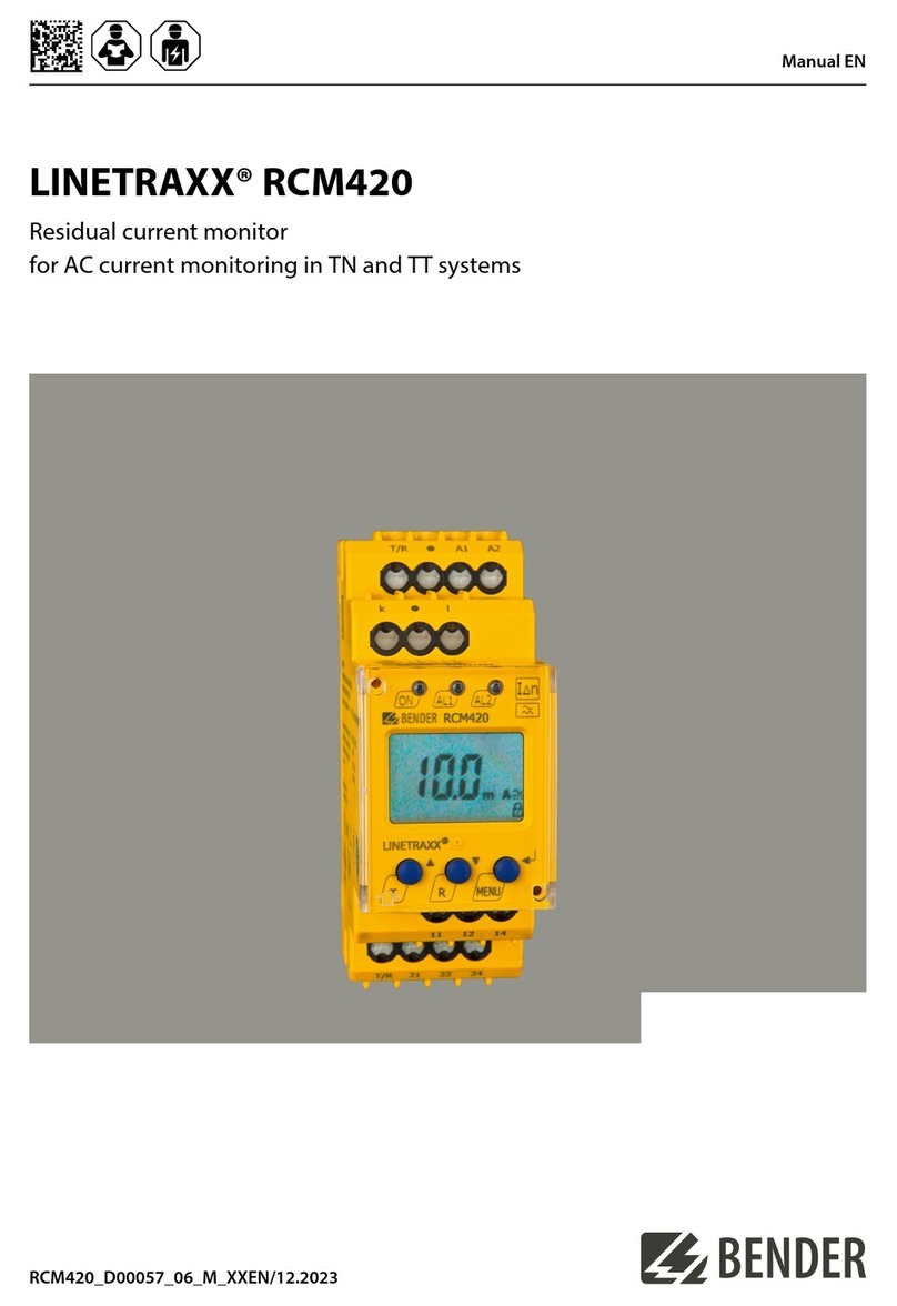
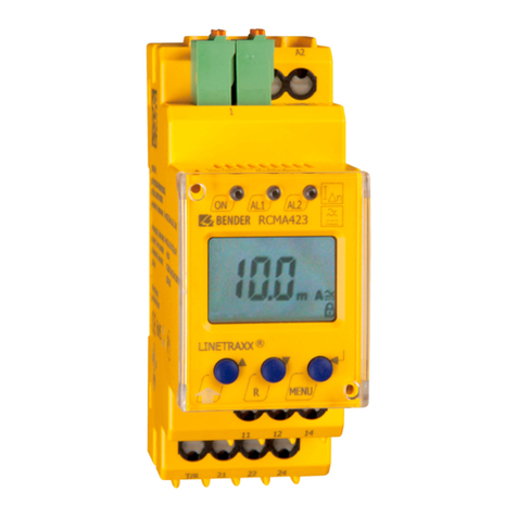
  9. Bender LINETRAXX RCM410R-1 User manual

Bender LINETRAXX RCM410R-1 User manual

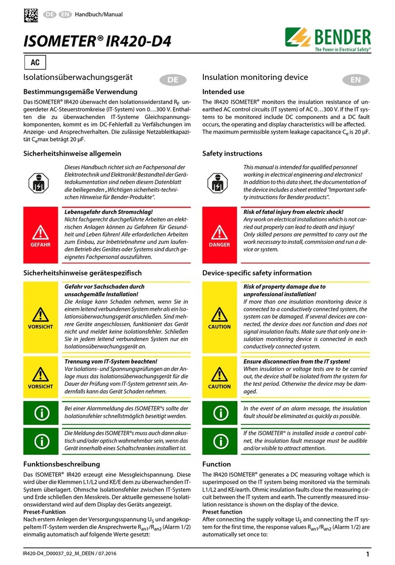
Intended Use
For intended operation, the specifications in the Technical
Data and in the manual must be observed.
Any use other than that described in this manual is regar-
ded as improper.
Mounting
Schraubbefestigung / Screw mounting
100
M4
Nm
1.0
!
i
Part of the device documentation, in addition to this
quickstart, are the enclosed "Safety instructions for
Bender products" and the corresponding manual,
which can be downloaded from https://www.bend-
er.de/en/service-support/downloads.
Scope of delivery:
RCM410R-1/-2, Quickstart DE/EN, Safety instructions
Ordering details:
AC and pulsed DC sensitive residual current
monitor
i
Bestandteil der Gerätedokumentation sind neben
dieser Kurzanleitung die „Sicherheitshinweise für
Bender-Produkte“unddasdazugehörigeHandbuch,
das unter https://www.bender.de/service-support/
downloadbereich herunter geladen werden kann.
Lieferumfang:
RCM410R-1/-2, Kurzanleitung DE/EN, Sicherheitshinweise
Bestellangaben:
Typ / Type Versorgungsspannung Us/ Supply voltage UsArt.-Nr. / Art. No. Handbuch Nr. / Manual No.
RCM410R-1 DC 24V B74602000 D00403
RCM410R-2 AC/DC 100…240V (47…63 Hz) B74603000
Bestimmungsgemäße Verwendung
Zum bestimmungsgemäßen Betrieb sind die Spezifika-
tionen in den Technischen Daten und im Handbuch zu
beachten.
Eine andere oder darüber hinausgehende Benutzung gilt
als nicht bestimmungsgemäß.
Montage
Montage auf Hutschiene / DIN rail mounting
1.
2.
3.
1.
Click!
2.
LINETRAXX® RCM410R-1/-2
Wechsel- und pulsstromsensitives Differenzstrom-
Überwachungsgerät
Montage
Mounting
Demontage
Removal
RCM410R_D00403_01_Q_DEEN /09.2020
Kurzanleitung / Quickstart-guide
18
8,8
100
109
93
64
48.5
45
1
65
35
2 x Ø 4,2
18
8,8
100
109
93
64
48.5
45
1
65
35
2 x Ø 4,2
ON
Bender
RCM410R
T / R
ton(s)
Ext 10 42
1
0,8
0,6
0,40,20
I∆n(A)
Ext 30 10 5
1
0,5
0,3
0,1,03,01
25
%
50
75
%
100
2
AL
1
S2S1 ** A2A2 A1A1
11 14 12
BA-+
Anschluss / Connection
Anschluss / Terminal Verbindung / Connection
A1, A2 Versorgungsspannung Us / Supply voltage Us
S1, S2 Messstromwandler / Current transformer
11, 14, 12 Alarmrelais K1 / Alarm relay K1
++24V
–Masse / Ground
ARS-485 A
BRS-485 B
S2
S1
A2
A1
US
CT
S2
S1
CT
A
B
+
–
14
12
11
24 V COM K1
Terminierung RS-485 erstes und letztes Gerät
Termination RS-485 first and last device
B
A
RS-485
120 Ω
> 0.1 W
i
Bei mehr als 16 Bus-Teilnehmern der
Gerätevariante RCM410R-2 ist die
Schnittstelle berührungssicher auszu-
führen, weil der max. zulässige
Gesamt-Arbeitsstrom von 0,5 mA über-
schritten werden kann.
i
If there are more than 16 bus devices of
the RCM410R-2 device variant, the in-
terface must be designed to be touch-
proof, because the maximum operat-
ing current of 0.5 mA could be exceed-
ed.
S2
L1 L2 L3 N
Verbraucher
Load
S1
11
14
12
RS-485
B
A
–
+24 V
+
S1 (k)
S2 (l)
RCM410R-1
S2
L1 L2 L3 N
Verbraucher
Load
S1
A1
US
~/+ ~/–
A2
RS-485
B
A
–
(+24 V) optional
+
11
14
12
S1 (k)
S2 (l)
RCM410R-2
I Vorsicht! Kurzschluss. Bei direktem Einschub fein-
drähtiger Leitungen in die Push-In-Klemmen kön-
nen gespleißte Drähte einen Kurzschluss verursa-
chen. Verwenden Sie Aderendhülsen.
I caution! Short circuit. When finely stranded cables
are inserted directly into the push-in terminals,
spliced wires can cause a short circuit. Use ferrules.
i
Nur Aderendhülsen 0,25 - 1,5 mm² verwenden.
Ab 1 mm² nur mit Crimpzange (ähnlich CRIMPFOX 6
/ Weidmüller PZ6/PZ6/5) verwenden.
i
Use ferrules 0.25 - 1.5 mm² only. From 1 mm², use
only with crimping pliers (similar to CRIMPFOX 6 /
Weidmüller PZ6/PZ6/5).
RCM410R-2RCM410R-1
i
*
i
*
i
* Achtung!Durch Kontaktströme in einem hohen
Bereich wird die Hartvergoldung der Relaiskontakte
beschädigt. Beschädigte Kontakte verhindern dann,
dass das Relais bei niedrigen Kontaktströmen kor-
rekt schaltet.
i
* Attention!High contact currents damage the hard
gold plating of the relay contacts. Damaged con-
tacts prevent the relay from switching correctly at
low contact currents.
<10 >1.5
10 1.5
10
1.5
<10 >1.5
10
1.5
10 1.5
<10
>1.5
10 1.5
10 1.5
2 RCM410R_D00403_01_Q_DEEN /09.2020
LINETRAXX® RCM410R-1/-2
i
If no entry is made for a period of 5 minutes, the
Addr. mode is automatically exited. The device then
adopts the currently set Modbus address.
Betriebsmodus ON / operating mode ON (Standard)
i
Wenn für den Zeitraum von 5 Minuten keine Eingabe
erfolgt, wird der Addr.-Modus automatisch verlas-
sen. Das Gerät übernimmt dann die aktuell einge-
stellte Modbus-Adresse.
T/R Funktionen / T/R functions (Konfiguration / configuration)
Übersicht / Overview
Addr.-Modus: Adressierung / Addr. mode: address setting
Modbus Adressen Eingabe mittels BCD-Code / Modbus address input via BCD
25%
50%
75%
100%
AL2
AL1
…
0 94321 …
25%
50%
75%
100%
AL2
AL1
…
090403020
10 …
25%
50%
75%
100%
AL2
AL1
0200
100
T / R
T / R
x [0…2]
T / R
2s
T / R
x [0…9]
T / R
2s
T / R
x [0…9]
T / R
2s
ONAddr.
LINETRAXX® RCM410R-1/-2
RCM410R_D00403_01_Q_DEEN /09.2020 3
ON
Bender
RCM410R
T / R
ton(s)
Ext 10 42
1
0,8
0,6
0,40,20
I∆n(A)
Ext 30 10 5
1
0,5
0,3
0,1,03,01
25
%
50
75
%
100
2
AL
1
S2S1 ** A2A2 A1A1
11 14 12
BA-+
1
2
3
4
5
6
7
9
8
Nr. No. Funktion / Function Bemerkung / Description
1 Kein Alarm / No alarm Gerät im Normalzustand / Device in normal condition
2IΔn ≥25% Fehlerstrom erkannt / Fault current detected
3IΔn ≥50% & AL1 (Vorwarnung / prewarning) Vorwarnung ausgelöst / Prewarning triggered
4IΔn ≥75% & AL1 (Vorwarnung / prewarning) Vorwarnung ausgelöst / Prewarning triggered
5IΔn ≥100% & AL1 & AL2
(Hauptalarm / main alarm)
Alarmrelais ist angezogen / Alarm relay is energised
6 Alarmhistorie / Alarm history Ein Fehler bestand / A fault existed
7 Anschlussfehler Messstromwandler/
Connection error CT
Fehlerbehebung bzw. Service erforderlich /
Troubleshooting or service required
8 Gerätefehler / Device error Das Gerät ist defekt /The device is defective.
9 NFC aktiv / NFC active NFC ist aktiviert (nur Service) ⁄
NFC is activated (service only)
ON Reset Test NFCactive/inactive Addr. ON
T / R
1 s 3 s 6 s 10 s 15 s
Technical data
Supply voltage
RCM410R-1
Supply voltage Us....................................................................DC 24 V
Tolerance Us...................................................................-30…+25 %
Power consumption.................................................................. ≤ 2 W
RCM410R-2
Supply voltage Us............................AC/DC 100…240 V (47…63 Hz)
Tolerance Us.............................................................................±15 %
Power consumption.................................................≤ 2 W / ≤ 3.5 VA
Measuring circuit
Measuring current transf. type ...........................................................
..............................................CTAC…, W…, WF…*, WR…, WS…
* Can only be used when CT connection monitoring is disabled on the
RCM410R.
Load.............................................................................................33 Ω
Operating characteristics ..........................................................Type A
Rated voltage Un..........see datasheet measuring current transformer
Frequency range..............................................................42…70 Hz)
Measuring range RMS.....................................................2 mA…50 A
Residual operating current IΔn......................................10 mA…30 A
Operating uncertainty...................................±10 % (at 0.5…5 x IΔn)
Relative uncertainty.......................................................... 0…–20 %
Contact data acc. to IEC 60947-5-1:
Utilisation category................AC 13 AC 14 DC-12 DC-12 DC-12
Rated op. voltage................... 230 V 230 V 24 V 110 V 220 V
Rated op. current..................... 5 A 3 A 1 A 0.2 A 0.1 A
Minimum contact rating................................1 mA at AC/DC ≥ 10 V *
* refers to relays that have not been operated with high contact currents.
Connection
Connection type...................................................................... push-in
Connection properties
rigid ................................................... 0.2…1.5 mm² (AWG 24…16)
flexible .............................................. 0.2…1.5 mm² (AWG 24…16)
with ferrule .............................................................0.25…0.75 mm²
with ferrule ..............................................................1.0…1.5 mm² *
* Use crimping pliers only (simliar CRIMPFOX 6 / Weidmüller PZ6/PZ6/5).
Technische Daten
Versorgungsspannung
RCM410R-1:
Versorgungsspannung Us........................................................DC 24 V
Toleranz von Us..............................................................-30…+25 %
Eigenverbrauch.........................................................................≤ 2 W
RCM410R-2:
Versorgungsspannung Us................AC/DC 100…240 V (47…63 Hz)
Toleranz von Us........................................................................±15 %
Eigenverbrauch....................................................... ≤ 2 W / ≤ 3,5 VA
Messkreis
Messstromwandlertyp........................................................................
..............................................CTAC…, W…, WF…*, WR…, WS…
* Einsatz nur bei deaktivierter Messstromwandler-Anschlussüberwachung am
RCM410R möglich.
Bürde...........................................................................................33 Ω
Ansprech-Charakteristik............................................................. Typ A
Bemessungsspannung Un...........siehe Datenblatt Messstromwandler
Frequenzbereich ............................................................... 42…70 Hz
Messbereich RMS............................................................2 mA…50 A
Ansprechdifferenzstrom IΔn...........................................10 mA…30 A
Betriebsmessabweichung...........................±10 % (bei 0,5…5 x IΔn)
Prozentuale Ansprechunsicherheit ................................... 0…–20 %
Kontaktdaten nach IEC 60947-5-1:
Gebrauchskategorie............... AC 13 AC 14 DC-12 DC-12 DC-12
Bem.betriebsspannung.......... 230 V 230 V 24 V 110 V 220 V
Bem.betriebsstrom.................. 5 A 3 A 1 A 0,2 A 0,1 A
Min. Kontaktbelastbarkeit ...........................1 mA bei AC/DC ≥ 10 V *
* bezieht sich auf Relais, die noch nicht mit hohen Kontaktströmen betrieben
wurden
Anschluss
Anschlussart............................................................................Push-In
Anschlussvermögen
starr .................................................. 0,2…1,5 mm² (AWG 24…16)
flexibel .............................................. 0,2…1,5 mm² (AWG 24…16)
mit Aderendhülse ...................................................0,25…0,75 mm²
mit Aderendhülse .....................................................1,0…1,5 mm² *
* nur Crimpzange (ähnlich CRIMPFOX 6 / Weidmüller PZ6/PZ6/5) verwenden.
LINETRAXX® RCM410R-1/-2
Alle Rechte vorbehalten.
Nachdruck und Vervielfältigung
nur mit Genehmigung des Herausgebers.
Bender GmbH & Co. KG
Postfach 1161 • 35301 Grünberg • Deutschland
Londorfer Str. 65 • 35305 Grünberg • Deutschland
Tel.: +49 6401 807-0 • Fax: +49 6401 807-259
E-Mail: [email protected] • www.bender.de
All rights reserved.
Reprinting and duplicating
only with permission of the publisher.
Bender GmbH & Co. KG
PO Box 1161 • 35301 Grünberg • Germany
Londorfer Str. 65 • 35305 Grünberg • Germany
Tel.: +49 6401 807-0 • Fax: +49 6401 807-259
E-Mail: [email protected] • www.bender.de

Other manuals for LINETRAXX RCM410R-1

1

This manual suits for next models

4

Other Bender Measuring Instrument manuals

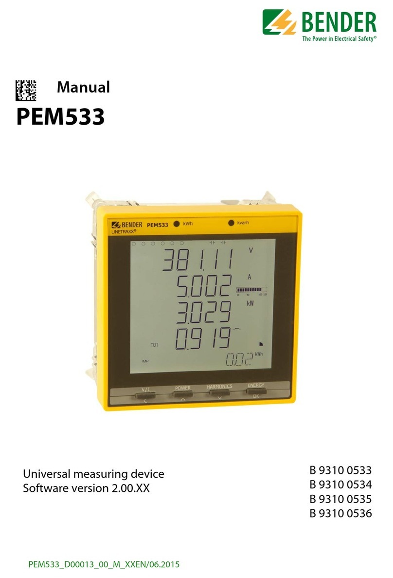
Bender PEM533 User manual

Bender

Bender PEM533 User manual

Bender ISOMETER isoHV425 User manual

Bender

Bender ISOMETER isoHV425 User manual

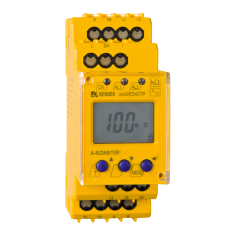
Bender isoMED427 User manual

Bender

Bender isoMED427 User manual

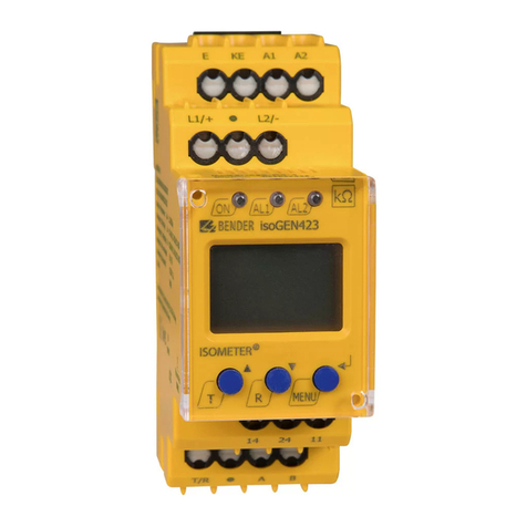
Bender ISOMETER isoGEN423-D4-4 User manual

Bender

Bender ISOMETER isoGEN423-D4-4 User manual

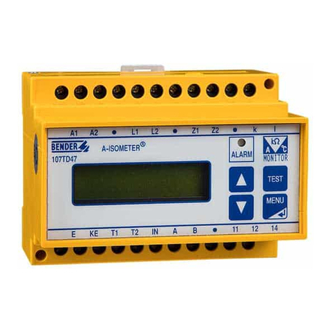
Bender ISOMETER 107TD47 User manual

Bender

Bender ISOMETER 107TD47 User manual

Bender PEM735 User manual

Bender

Bender PEM735 User manual

Bender ISOMETER iso1685FR User manual

Bender

Bender ISOMETER iso1685FR User manual

Bender LINETRAXX RCM420 User manual

Bender

Bender LINETRAXX RCM420 User manual

Bender MK-BN User manual

Bender

Bender MK-BN User manual

Bender Isometer IR420-D4 User manual

Bender

Bender Isometer IR420-D4 User manual

Bender COM465IP User manual

Bender

Bender COM465IP User manual

Bender ISOMETER isoHR685W Series User manual

Bender

Bender ISOMETER isoHR685W Series User manual

Bender ISOMETER iso1685DP User manual

Bender

Bender ISOMETER iso1685DP User manual

Bender EDS44-CN Series User manual

Bender

Bender EDS44-CN Series User manual

Bender RC48N User manual

Bender

Bender RC48N User manual

Bender ISOMETER iso165C User manual

Bender

Bender ISOMETER iso165C User manual

Bender NGRM500 User manual

Bender

Bender NGRM500 User manual

Bender A-ISOMETER IR425 User manual

Bender

Bender A-ISOMETER IR425 User manual

Bender COM465IP User manual

Bender

Bender COM465IP User manual

Bender ISOMETER iso685W-S-B User manual

Bender

Bender ISOMETER iso685W-S-B User manual

Bender MRCDB423 Series User manual

Bender

Bender MRCDB423 Series User manual

Bender W0-S20 User manual

Bender

Bender W0-S20 User manual

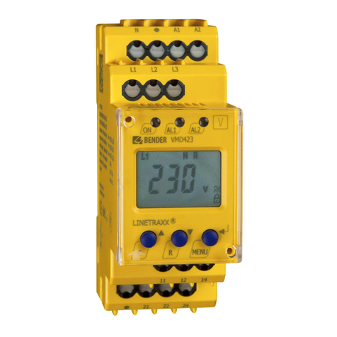
Bender VMD423 User manual

Bender

Bender VMD423 User manual

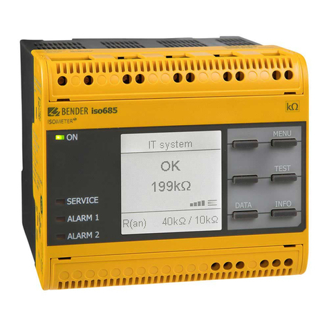
Bender iso685-S Series Guide

Bender

Bender iso685-S Series Guide

Popular Measuring Instrument manuals by other brands

ACU-RITE 00325CADI instruction manual

ACU-RITE

ACU-RITE 00325CADI instruction manual

Centech 92953 Operating information

Centech

Centech 92953 Operating information

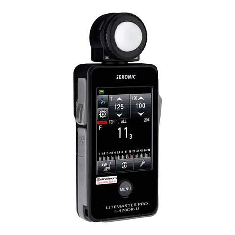
Sekonic LITEMASTER PRO Service manual

Sekonic

Sekonic LITEMASTER PRO Service manual

SIGMA TEK TS 041 instruction manual

SIGMA TEK

SIGMA TEK TS 041 instruction manual

SignalFire AI-9 user manual
SignalFire

SignalFire AI-9 user manual

FTS Radar Stage Sensor operating manual

FTS

FTS Radar Stage Sensor operating manual

Swann AMI Rescon Operator's manual

Swann

Swann AMI Rescon Operator's manual

IMG STAGE LINE LSX-300TEXT instruction manual

IMG STAGE LINE

IMG STAGE LINE LSX-300TEXT instruction manual

Ibiza LAS-RG-OUTDOOR user manual

Ibiza

Ibiza LAS-RG-OUTDOOR user manual

Chauvin Arnoux ORITEL RW 521 user manual

Chauvin Arnoux

Chauvin Arnoux ORITEL RW 521 user manual

CET iMeter 6 user manual

CET

CET iMeter 6 user manual

janitza UMG 96-PA User manual and technical data

janitza

janitza UMG 96-PA User manual and technical data

SKF TMEH 1 Instructions for use

SKF

SKF TMEH 1 Instructions for use

Runyon RHOPOINT METER instruction manual

Runyon

Runyon RHOPOINT METER instruction manual

Trico DR-7 user manual

Trico

Trico DR-7 user manual

Blonder tongue BTPRO-8000S user manual

Blonder tongue

Blonder tongue BTPRO-8000S user manual

shelyak LHIRES III Assembling Procedure

shelyak

shelyak LHIRES III Assembling Procedure

PASCO SP-9285 instruction sheet

PASCO

PASCO SP-9285 instruction sheet

manuals.online logo
manuals.online logoBrands
  • About & Mission
  • Contact us
  • Privacy Policy
  • Terms and Conditions

Copyright 2025 Manuals.Online. All Rights Reserved.