manuals.online logo
Brands
  1. Home
  2. •
  3. Brands
  4. •
  5. Bender
  6. •
  7. Measuring Instrument
  8. •
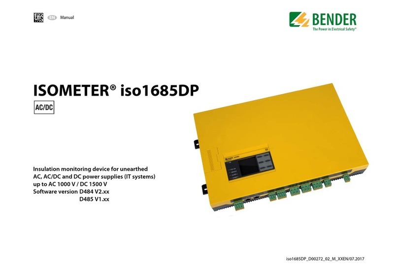
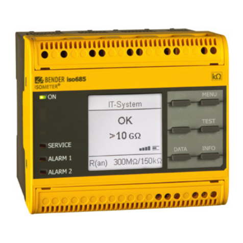
  9. Bender iso685-S Series Guide

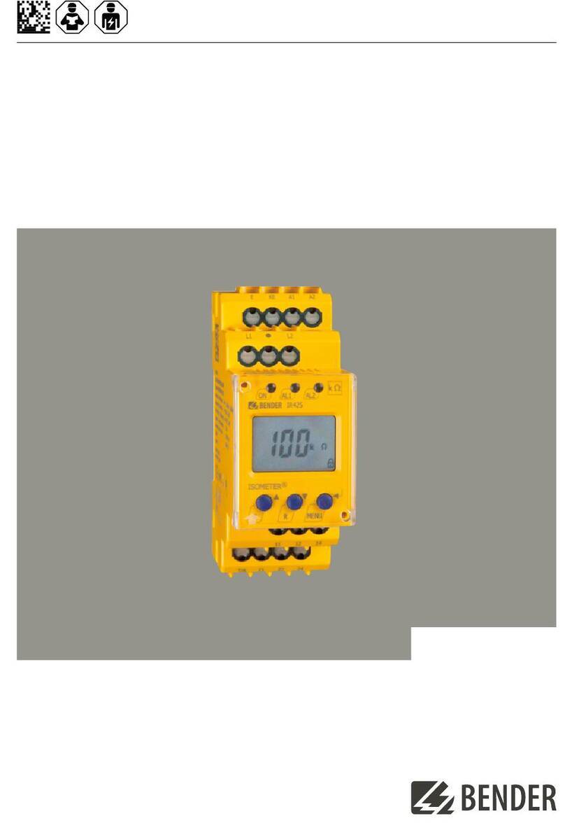
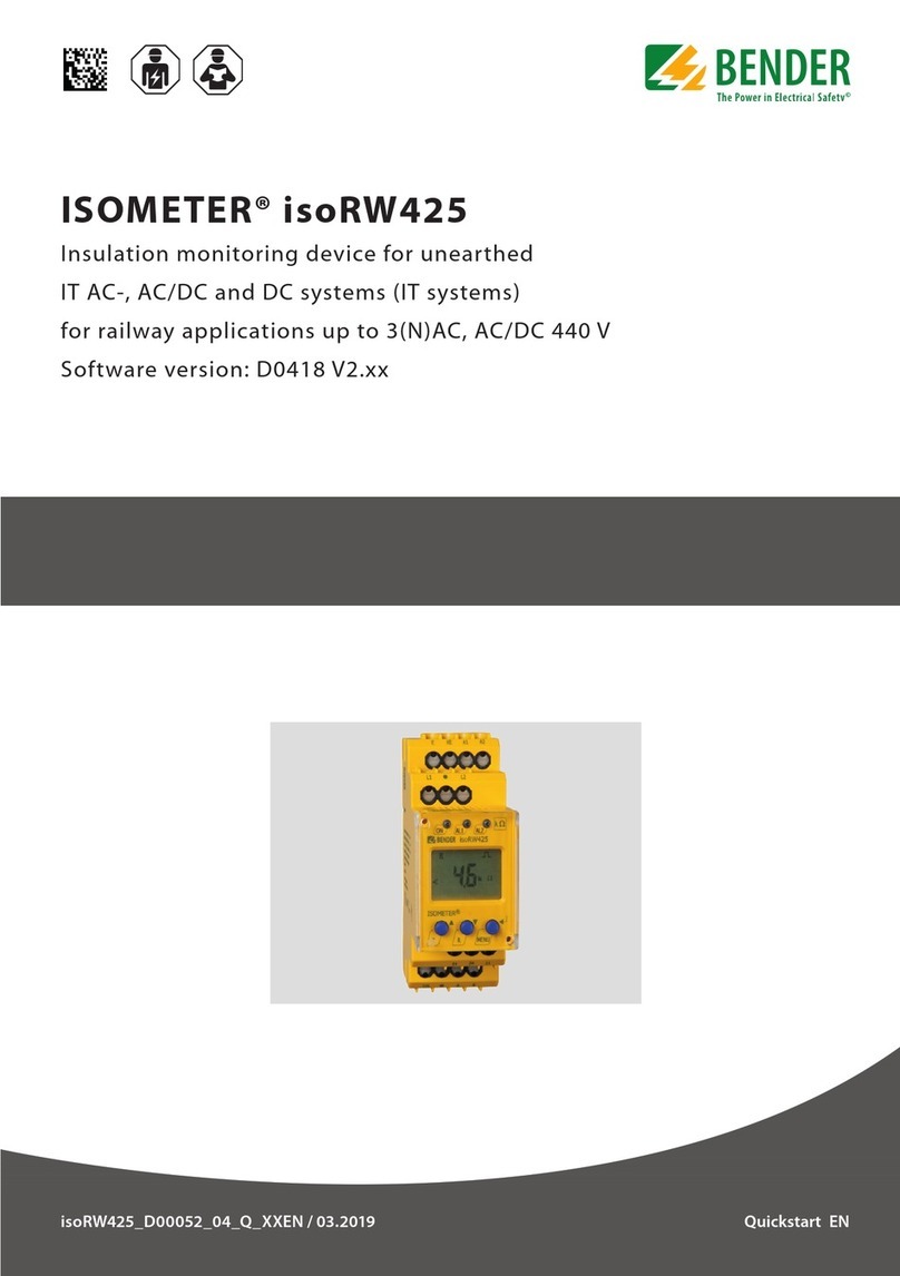
Bender iso685-S Series Guide

Inbetriebnahme eines iso685-S…-Gerätes ohne angeschlossenes Dis-
play FP200(W)
Commissioning iso685-S… devices without a connected Display
FP200(W)
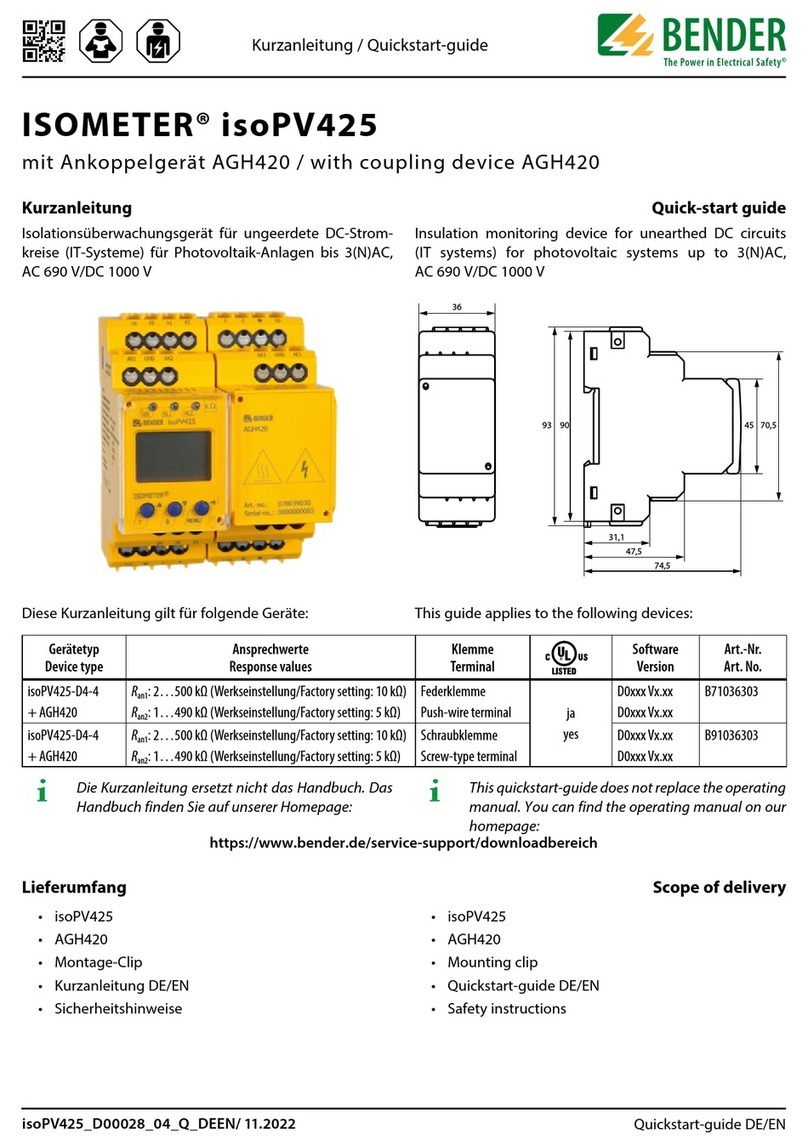
Gültig ab Seriennummer / Valid from serial number 2105xxx
iso685-S, iso685-S-B, iso685-S-P
Anlageblatt / Application note DE/ENiso685-S-x_D00022_00_B_DEEN.pdf / 06.2021
2 iso685-S-x_D00022_00_B_DEEN.pdf / 06.2021
iso685-S, iso685-S-B, iso685-S-P
Einsatz von iso685-S…-Geräten
iso685-S…-Geräte entsprechen auch ohne Displayeinheit
FP200(W) den Produktnormen DIN EN 61557-8 und IEC
61557-8. Der Schreibzugriff von einem Webserver ist
werkseitig mit dem Status „Zulassen“ konfiguriert und
kann nur über eine angeschlossene Displayeinheit
FP200(W) auf „Verweigern“ umgestellt werden.
Die Einstellungen der Parameter zur Inbetriebnahme wer-
den über den geräteinternen Webserver vorgenommen.
Diese Kurzanleitung ersetzt nicht das Handbuch. Beachten
Sie zwingend die Sicherheitshinweise der beigelegten
Dokumente und des Handbuches. Das Handbuch steht
unter folgender Adresse zum Download bereit.
Gerät / Device Bestellnummer / Ordering number
iso685(W)-S B91067110(W)
iso685(W)-S-B B91067120(W)
iso685(W)-S-P B91067130(W)
iso685(W)-S-x-YY länderspezische Varianten auf Anfrage
country-specic variants on request
Use of iso685-S... devices
iso685-S... devices comply with the product standards DIN
EN 61557-8 and IEC 61557-8 even without an FP200(W)
display unit. Write access from a web server is is set to
”Allow“ by default and can only be changed to ”Deny“ via
a connected FP200(W) display unit.
The parameter settings are made via the device-internal
web server. These quick-start guide does not replace the
manual. It is imperative that you observe the safety inst-
ructions in the enclosed documents and the manual. The
manual is available for download at the following ad-
dress.
Device
iso685(W)-S B91067110(W)
iso685(W)-S-B B91067120(W)
iso685(W)-S-P B91067130(W)
iso685(W)-S-x-YY
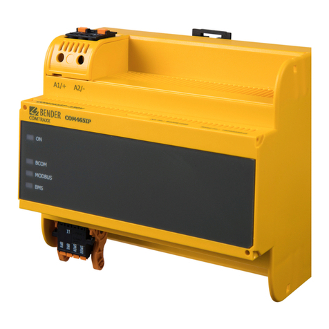
Netzwerkanschluss und Webzugriff
Der Anschluss des Netzwerkkabels (RJ45) erfolgt zwin-
gend an der Buchse ETH an der Unterseite des Gerätes.
I Vorsicht! Beschädigung des Geräts durch fal-
schen Anschluss des RJ45-Netzwerkkabels. Der
Anschluss eines Netzwerkkabels an die Buchse
REMOTE auf der Frontseite des Geräts führt dazu,
dass das Gerät beschädigt wird. Für die Integration
in ein TCP-IP-Kommunikationsnetzwerk ist die
Buchse ETH an der Unterseite des Geräts zu verwen-
den.
Passen Sie die Systemumgebung des Netzwerks so an,
dass die Adresse 192.168.0.x im System erkannt wird.
Fragen sie dazu den zuständigen System-Administrator.
Geben Sie dann die IP-Adresse ‚192.168.0.5‘ in den Browser
ein.
REMOTE
20
242221141211RETHX1
1918171615
Network connection and web access
The network cable (RJ45) must be connected to the ETH
socket at the bottom of the device.
I caution! Damage to the device due to incorrect
connection of the network cable. Connecting a
network cable to the REMOTE socket at the front of
the device will damage the device. For integration
into a TCP-IP communication network, use the ETH
socket at the bottom of the device.
Adjust the system environment of the network so that the
address 192.168.0.x is recognised in the system. For this
purpose, please refer to your system administrator.
Afterwards enter the IP address ”192.168.0.5“ in the brow-
ser.
iso685-S, iso685-S-B, iso685-S-P
iso685-S-x_D00022_00_B_DEEN.pdf / 06.2021 3
Nicht sicher | 192.168.0.5/#/home
http://192.168.0.5
Erstinbetriebnahme
Netzwerkfunktion überprüfen!
Wenn das Gerät in ein Netzwerk integriert ist, muss der
Einfluss auf das Netzwerk mit ein- und ausgeschaltetem
Gerät überprüft werden.
192.168.0.5
255.255.255.0
192.168.0.xxx
255.255.255.0
Initial commissioning
Check network function!
When the device has been integrated into a network, the
influence on the network has to be checked with the de-
vice switched on and off.
Sprache einstellen
Die hier eingestellte Sprache wird im Menü und bei Mel-
dungen des Gerätes verwendet.
Set language
The language selected here will be used in the menu and
for device messages.
4 iso685-S-x_D00022_00_B_DEEN.pdf / 06.2021
iso685-S, iso685-S-B, iso685-S-P
Datum und Uhrzeit einstellen
Nur wenn das richtige Datum und die richtige Uhrzeit ein-
gestellt ist, können Alarmmeldungen im Historienspeicher
und der Verlauf des Isolationswiderstandes im isoGraph
richtig zugeordnet werden.
Set date and time
Alarm messages in the history memory and the insulation
resistance value over time can only be assigned correctly
to the isoGraph when date and time are set correctly.
iso685-S, iso685-S-B, iso685-S-P
iso685-S-x_D00022_00_B_DEEN.pdf / 06.2021 5
Profil einstellen [1]
Um das Isolationsüberwachungsgerät optimal auf das zu
überwachende Netz einzustellen, können Sie hier ein zu
Ihrer Anlage passendes Profil auswählen. Eine Übersicht
über die Profile finden Sie im Kapitel „Technische Daten“.
Das Profil „Leistungskreise“ ist für die meisten IT-Systeme
geeignet.
Netzform einstellen [2]
Durch das Einstellen der Netzform passt sich das
Isolationsüberwachungsgerät optimal auf das zu überwa-
chende Netz an. Für die korrekte Ermittlung des
Isolationswiderstandes ist die Netzform eine notwendige
Information für das Isolationsüberwachungsgerät.
Ankopplung (nicht bei iso685-S-P) [3]
Ein an das Isolationsüberwachungsgerät angeschlossenes
Ankoppelgerät zur Erhöhung der Netznennspannung
muss hier parametriert werden. Die Messung des
Isolationswiderstandes berücksichtigt die Parameter des
angeschlossenen Ankoppelgerätes. Ist kein Ankoppelgerät
vorhanden, stellen Sie none ein.
Set profile [1]
In order to optimally adapt the insulation monitoring de-
vice to the system to be monitored, select a profile here
that suits your system. For an overview of the profiles, re-
fer to ”Technical Data“. The ”Power circuits“ profile is suita-
ble for most of the IT systems.
Set system type [2]
By setting the system type, the insulation monitoring de-
vice can be optimally adapted to the system to be monito-
red. The system type is essential information for the insu-
lation monitoring device in order to determine the insula-
tion resistance correctly.
Select a coupling device [3]
A coupling device connected to the insulation monitoring
device (to increase the nominal system voltage) must be
programmed here. The measurement of the insulation
resistance takes into account the parameters of the con-
nected coupling device. If no coupling device is available,
set to none.
1
2
3
6 iso685-S-x_D00022_00_B_DEEN.pdf / 06.2021
iso685-S, iso685-S-B, iso685-S-P
Ansprechwert Ran1 für Alarm 1 einstellen [4]
Hier können Sie den Ansprechwert für den Voralarm ein-
stellen. Empfehlung für den Voralarm ist ein Wert von 300
Ω/V
Ansprechwert Ran2 für Alarm 2 einstellen [5]
Hier können Sie den Ansprechwert für den Hauptalarm
einstellen. Empfehlung für den Hauptalarm sind 100 Ω/V.
Set response value Ran1 for alarm 1 [4]
You can set the prewarning response value here.
A value of 300 Ω/V is recommended for prewarning.
Set response value Ran2 for alarm 2 [5]
You can set the prewarning response value here. A value
of 100 Ω/V is recommended for prewarning.
4
5
iso685-S, iso685-S-B, iso685-S-P
iso685-S-x_D00022_00_B_DEEN.pdf / 06.2021 7
EDS Strom einstellen (nur iso685-S-P) [6]
Stellen Sie den maximalen Prüfstrom ein.
EDS441: 1-5 mA
EDS440: 10-50 mA
EDS-Modus einstellen (nur iso685-S-P) [7]
Stellen Sie den Modus für die Isolationsfehlersuche
auf „manuell“, „automatisch“ oder „1 Umlauf“.
Set EDS current (iso685-S-P only) [6]
Set the maximum locating current.
EDS441: 1-5 mA
EDS440: 10-50 mA
Set EDS mode (iso685-S-P only) [7]
Set the mode for the insulation fault location to
”manual“, ”automatic“ or ”1 cycle“.
6
7
8 iso685-S-x_D00022_00_B_DEEN.pdf / 06.2021
iso685-S, iso685-S-B, iso685-S-P
Inbetriebnahme EDS (nur iso685-S-P)
Um nach der Inbetriebnahme des ISOMETER®s ein EDS in
Betrieb zu nehmen, gehen Sie wie folgt vor:
Suchen Sie zuerst nach allen verfügbaren Messkanälen.
Commission EDS (iso685-S-P only)
Proceed as follows to put into operation an EDS after com-
missioning the ISOMETER®:
First, search for all available measuring channels.
iso685-S, iso685-S-B, iso685-S-P
iso685-S-x_D00022_00_B_DEEN.pdf / 06.2021 9
Übersicht der angeschlossenen Messstromwandler Overview of the connected measuring current transfor-
mers
8 9
Kanäle aktivieren [8]
Aktivieren Sie alle oder nur ausgewählte Messkanäle.
Wählen Sie dazu den gewünschten Punkt im Menü aus,
bestätigen Sie Ihre Auswahl mit „Änderungen speichern“.
Warten Sie, bis der Prozess abgeschlossen ist.
Ansprechwert IΔLeinstellen [9]
Prüfen Sie, ob der maximale Prüfstrom zum EDS passt und
passen Sie ihn gegebenenfalls an (siehe Abschnitt oben
„EDS Strom einstellen“). Warten Sie, bis der Prozess abge-
schlossen ist.
Activate channels [8]
Activate all or only the selected measuring channels.
Additionally, select the required menu item, confirm your
selection with "Save changes".
Wait until the process is completed.
Set response value IΔL[9]
Check whether the maximum locating is suitable for the
EDS (refer to ”Set EDS current“ above). Wait until the pro-
cess is completed.
8 9
10 iso685-S-x_D00022_00_B_DEEN.pdf / 06.2021
iso685-S, iso685-S-B, iso685-S-P
iso685-S-x_D00022_00_B_DEEN.pdf / 06.2021 11
Endkunden Betreuung & Beratung / Support
Technische Unterstützung telefonisch oder per E-Mail für
alle Bender-Produkte
• Fragen zu speziellen Kundenapplikationen
• Inbetriebnahme
• Störungsbeseitigung
Telefon: +49 6401 807-760
(365 Tage von 07:00 - 20:00 Uhr [MEZ/UTC +1])
Fax: +49 6401 807-259
0700BenderHelp (Telefon und Fax nur in Deutschland)
E-Mail: [email protected]
End customer support and advice
Technical support by phone or e-mail for all Bender pro-
ducts
• Questions concerning specific customer applications
• Commissioning
• Troubleshooting
Telephone: +49 6401 807-760
(365 days from 07:00 a.m. to 08:00 p.m. [MEZ/UTC +1])
Fax: +49 6401 807-259
E-mail: [email protected]
iso685-S, iso685-S-B, iso685-S-P
Alle Rechte vorbehalten.
Nachdruck und Vervielfältigung
nur mit Genehmigung des Herausgebers.
Bender GmbH & Co. KG
Postfach 1161 • 35301 Grünberg • Deutschland
Londorfer Str. 65 • 35305 Grünberg • Deutschland
Tel.: +49 6401 807-0 • Fax: +49 6401 807-259
E-Mail: [email protected] • www.bender.de
All rights reserved.
Reprinting and duplicating
only with permission of the publisher.
Bender GmbH & Co. KG
PO Box 1161 • 35301 Grünberg • Germany
Londorfer Str. 65 • 35305 Grünberg • Germany
Tel.: +49 6401 807-0 • Fax: +49 6401 807-259
E-Mail: [email protected] • www.bender.de

This manual suits for next models

12

Other Bender Measuring Instrument manuals

Bender ISOMETER iso415R User manual

Bender

Bender ISOMETER iso415R User manual

Bender PEM735 User manual

Bender

Bender PEM735 User manual

Bender COM465IP User manual

Bender

Bender COM465IP User manual

Bender ISOMETER isoCHA425HV User manual

Bender

Bender ISOMETER isoCHA425HV User manual

Bender ISOMETER 107TD47 User manual

Bender

Bender ISOMETER 107TD47 User manual

Bender CMD420 User manual

Bender

Bender CMD420 User manual

Bender ISOMETER isoGEN423 User manual

Bender

Bender ISOMETER isoGEN423 User manual

Bender COMTRAXX MK2430 User manual

Bender

Bender COMTRAXX MK2430 User manual

Bender ISOMETER IR423-D4 User manual

Bender

Bender ISOMETER IR423-D4 User manual

Bender RCMA423AS User manual

Bender

Bender RCMA423AS User manual

Bender COM465IP User manual

Bender

Bender COM465IP User manual

Bender ISOMETER isoPV425 with AGH420 User manual

Bender

Bender ISOMETER isoPV425 with AGH420 User manual

Bender ISOMETER IR425-D4 User manual

Bender

Bender ISOMETER IR425-D4 User manual

Bender COMTRAXX MK800 User manual

Bender

Bender COMTRAXX MK800 User manual

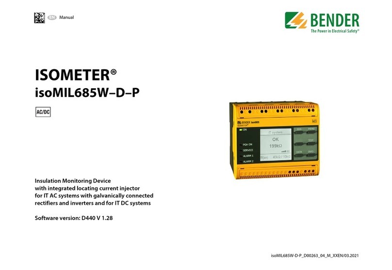
Bender ISOMETER iso685-D-P User manual

Bender

Bender ISOMETER iso685-D-P User manual

Bender RDC104-4 User manual

Bender

Bender RDC104-4 User manual

Bender ISOMETER IR425-D4 User manual

Bender

Bender ISOMETER IR425-D4 User manual

Bender ISOMETER isoUG425 User manual

Bender

Bender ISOMETER isoUG425 User manual

Bender VMD423 User manual

Bender

Bender VMD423 User manual

Bender COMTRAXX MK800 User manual

Bender

Bender COMTRAXX MK800 User manual

Bender ISOMETER IR1575H User manual

Bender

Bender ISOMETER IR1575H User manual

Bender ISOMETER isoHR685W-x-I-B User manual

Bender

Bender ISOMETER isoHR685W-x-I-B User manual

Bender RCMB330 User manual

Bender

Bender RCMB330 User manual

Bender ISOMETER isoCHA425 User manual

Bender

Bender ISOMETER isoCHA425 User manual

Popular Measuring Instrument manuals by other brands

Sigma Metalytics Precious Metal Verifier INVESTOR 3012 manual

Sigma Metalytics

Sigma Metalytics Precious Metal Verifier INVESTOR 3012 manual

Storch HPM 3000 instruction manual

Storch

Storch HPM 3000 instruction manual

Doran SMARTLINK 360SLT2 manual

Doran

Doran SMARTLINK 360SLT2 manual

SATO KEIRYOKI SK-630PH Series instruction manual

SATO KEIRYOKI

SATO KEIRYOKI SK-630PH Series instruction manual

madur electronics GA-60 manual

madur electronics

madur electronics GA-60 manual

Berner BLM 80 manual

Berner

Berner BLM 80 manual

Brooks 5850 S Installation and operation manual

Brooks

Brooks 5850 S Installation and operation manual

GREISINGER G 1500 Quick reference guide

GREISINGER

GREISINGER G 1500 Quick reference guide

Kestrel 3500 Delta T quick start guide

Kestrel

Kestrel 3500 Delta T quick start guide

Simex SRP-94-XC user manual

Simex

Simex SRP-94-XC user manual

XC-Tracer Mini II user manual

XC-Tracer

XC-Tracer Mini II user manual

Fluke Calibration 6050H Final assembly guide

Fluke Calibration

Fluke Calibration 6050H Final assembly guide

Xylem WTW OxiTop-IDS Multi 3630 IDS operating manual

Xylem

Xylem WTW OxiTop-IDS Multi 3630 IDS operating manual

Chopin RHEO F4 user manual

Chopin

Chopin RHEO F4 user manual

entegris InVue GV148 user guide

entegris

entegris InVue GV148 user guide

Chauvin Arnoux CA 10141E user manual

Chauvin Arnoux

Chauvin Arnoux CA 10141E user manual

Anritsu Site Master S331L SCPI Programming Manual

Anritsu

Anritsu Site Master S331L SCPI Programming Manual

HP 85108A System manual

HP

HP 85108A System manual

manuals.online logo
manuals.online logoBrands
  • About & Mission
  • Contact us
  • Privacy Policy
  • Terms and Conditions

Copyright 2025 Manuals.Online. All Rights Reserved.