manuals.online logo
Brands
  1. Home
  2. •
  3. Brands
  4. •
  5. 3One data
  6. •
  7. Switch
  8. •
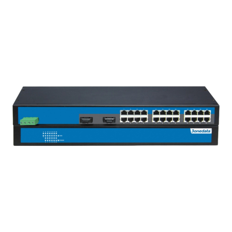
  9. 3One data ES2010G-2GS User manual

3One data ES2010G-2GS User manual

- 1 -
ES2010G-2GS
Full Gigabit Ethernet Switch
User manual
Shenzhen 3onedata Technology Co., Ltd.
Tel: +86-755-26702668 Fax: +86-755-26703485
www.3onedata.com
【Summarize】
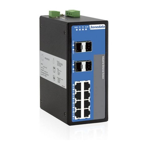
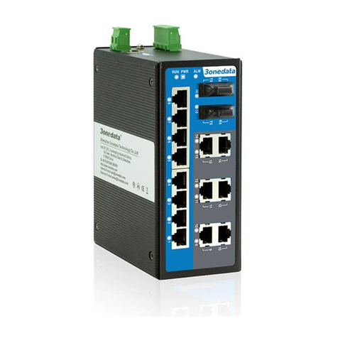
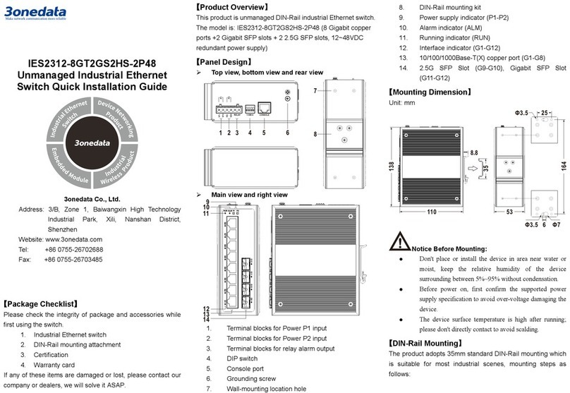
ES2010G-2GS is a kind of full gigabit unmanaged Ethernet
switch, it support 8 port 10/100/1000 Base-T(X) RJ45 Ethernet
and 2 port Gigabit SFP slot, DC power supply (12-48VDC). It
adopted no fan, low power consumption design, IP40, corrugate
high strength iron shell, the performance is more steadily. The
product accorded with CE, FCC standard and Industrial 4 grades,
DIN rail installation and wide operating temperature (0~55℃), it
can satisfied some kinds of industrial environment, it can provide
reliable and quickly solution for your Ethernet device.
【Packing list】
The Gigabit Ethernet switch is shipped with the following items.
If any of these items are missing or damaged, please contact your
customer service representative for assistance.
Gigabit Ethernet Switch ⅹ1
User manual ⅹ1
DIN-Rail mounting kit ⅹ1
Warranty card ⅹ1
【Features】
Support 8 port 10/100/1000Base-TX and 2 port Gigabit SFP
slots
Support IEEE802.3/802.3u/802.3x/802.3z/802.3ab store and
forward
Ethernet port support 10/100/1000M self-adaption
Support redundant power input (DC12~48V), support
reverse connection protection
Support 0~55℃working temperature
IP40 protect grade, high strength iron shell
DIN Rail installation.
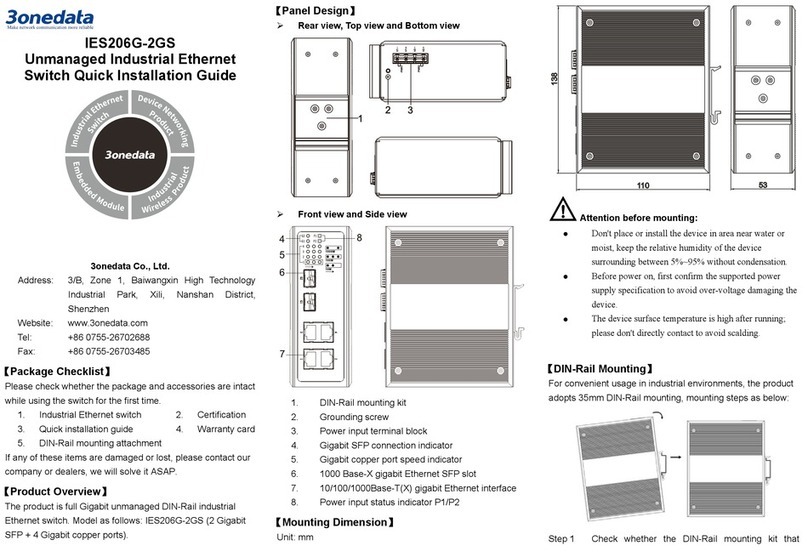
【Panel layout】
Vertical view and bottom view
Side view
Front view
- 2 -
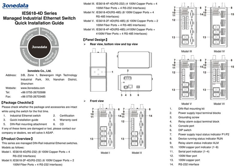
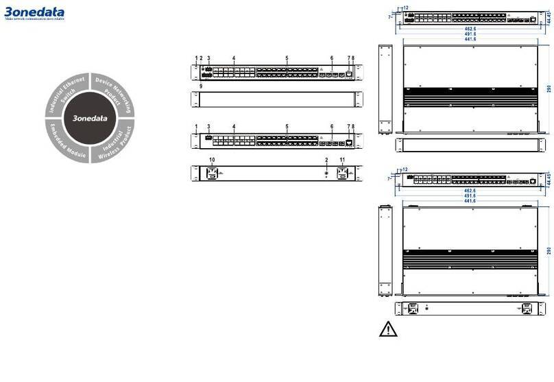
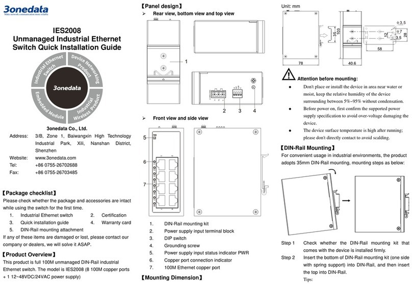
1. DIP Switch
2. Power input terminal block (4 bits)
3. Ground screw
4. DIN-Rail mounting kit
5. Gigabit SFP port
6. Power indicator
7. 10Base-T /100Base-TX/1000Base-TX Ethernet port
8. Gigabit Ethernet port indicator
【Dimension】
Unit (mm)
【Power supply input】
The Ethernet switch provided 4 bit power supply input terminal
block, support DC input. DC power supply input supported
redundancy function, provided PWR1 and PWR2 power input,
can use for single, and can connect 2 separately power supply
system, use 1 pair terminal block connect the device at the same
time. If one of the power systems broke, the device can work
un-interruptible. Built-in overcorrect protection, Reverse
connection protection. Voltage input range is 12 ~48VDC
(terminal block defined as: V1-、V1+、V2-、V2+).
【DIP switch】
The switch provided 4 bits DIP switch to do function configure
(ON is enable), 1 is flow control, 2 is fiber port trunking, 3 is port
isolation, 4 is keep for future function.
【Communication connector】
10/100/1000BaseT(X) Ethernet port
The pinout of RJ45 port display as below, connect by UTP or STP.
The connect distance is no more than 100m. 1000Mbps is used
120Ω of UTP 5e; 100Mbps is used 120Ω of UTP 5; 10Mbps is
used 120Ω of UTP 3, 4, 5.
RJ 45 port support automatic MDI/MDI-X operation. That can
connect the PC, Server, Converter and HUB. Pin 1, 2, 3, 4, 5, 6, 7,
8 Corresponding connections in MDI. 1→3, 2→6, 3→1, 4→7,
5→8, 6→2, 7→4, 8→5, are used as cross wiring in the MDI-X
port of Converter and HUB. In MDI/MDI-X, 100/1000Base-TX
PIN defines is as follows:
PIN
MDI
MDI-X
1
BI_DA+/TX+
BI_DB+/RX+
2
BI_DA-/TX-
BI_DB-/RX-
3
BI_DB+/RX+
BI_DA+/TX+
4
BI_DC+/—
BI_DD+/—
5
BI_DC-/—
BI_DD-/—
6
BI_DB-/RX-
BI_DA-/TX-
7
BI_DD+/—
BI_DC+/—
8
BI_DD-/—
BI_DC-/—
Note:10Base-T/100Base-TX, “TX±”transmit data±, “RX±”receive data±,
“—”not use.
Gigabit MDI (straight-through cable)
Gigabit MDI-X (Cross over cable)
MDI/MDI-X auto connection makes switch easy to use for
customers without considering the type of network cable.
1000Base SFP fiber port(mini-GBIC)
1000Base-FX SFP fiber port adopts gigabit mini-GBIC
transmission, can choice different SFP module according to
different transfer distance. Fiber interface must use for pair, TX
port is transmit side, must connect to RX (receive side). The fiber
interface support loss line indicator.
Suppose: If you make your own cable, we suggest labeling the
two sides of the same line with the same letter (A-to-A and
B-to-B, shown as below, or A1-to-A2 and B1-to-B2).
1 8
- 3 -
【LED Indicator】
LED indictor light on the front panel of product, the function of
each LED is described in the table as below.
System indication LED
LED
State
Description
P1, P2
ON
Power is being supplied to power
input PWR input
OFF
Power is not being supplied to
power input PWR input
LINK/ACT
(G1~G10)
ON
Port connection regular.
Blinking
Port connection active
OFF
Port had no connection.
【Installation】
Before installation, confirm that the work environment meet the
installation require, including the power needs and abundant
space. Whether it is close to the connection equipment and other
equipments are prepared or not.
1. Avoid in the sunshine, keep away from the heat fountainhead or
the area where in intense EMI.
2. Examine the cables and plugs that installation requirements.
3. Examine whether the cables be seemly or not (less than 100m)
according to reasonable scheme.
4. Power: 12-48VDC power input
5. Environment: working temperature: 0~55℃
Storage Temperature: -10~65℃
Relative humidity 5%~95%
DIN Rail Installation
In order to use in industrial environments expediently, the product
adopt 35mm DIN-Rail installation, the installation steps as below:
1. Examine the DIN-Rail attachment
2. Examine DIN Rail whether be firm and the position is
suitability or not.
3. Insert the top of the DIN-Rail into the slot just below the
stiff metal spring.
4. The DIN-Rail attachment unit will snap into place as shown
below.
Wiring Requirements
Cable laying need to meet the following requirements,
1. It is needed to check whether the type, quantity and
specification of cable match the requirement before cable
laying;
2. It is needed to check the cable is damaged or not, factory
records and quality assurance booklet before cable laying;
3. The required cable specification, quantity, direction and
laying position need to match construction requirements, and
cable length depends on actual position;
4. All the cable cannot have break-down and terminal in the
middle;
5. Cables should be straight in the hallways and turning;
6. Cable should be straight in the groove, and cannot beyond the
groove in case of holding back the inlet and outlet holes.
Cables should be banded and fixed when they are out of the
groove;
7. User cable should be separated from the power lines. Cables,
power lines and grounding lines cannot be overlapped and
mixed when they are in the same groove road. When cable is
too long, it cannot hold down other cable, but structure in the
middle of alignment rack;
8. Pigtail cannot be tied and swerved as less as possible.
Swerving radius cannot be too small (small swerving causes
terrible loss of link). Its banding should be moderate, not too
tight, and should be separated from other cables;
9. It should have corresponding simple signal at both sides of the
cable for maintaining.
【Specification】
Technology
Standard: IEEE802.3, IEEE802.3u, IEEE802.3x, IEEE802.3z,
IEEE802.3ab
Flow control: IEEE802.3x, back pressure control
Interface
Electric port: 10Base-T/100Base-TX/1000 Base-TX auto speed
control, Half/full duplex and MDI/MDI-X auto detect
Gigabit SFP port: 1000Base-X, SFP slot
Exchange of attribute:
Transmission: Store and forward
System exchange bandwidth: 20Gbps
Memory: 1Mbit
MAC address: 8K
LED indicator
Interface indicator: Link (G1~G10)
DC Power supply indicator: P1, P2
Transfer distance
Twisted cable: 100M (standard CAT5/CAT5e cable)
Multi-mode: 1310nm, 2Km
Single-mode: 1310nm, 20/40Km
1550nm, 60/80/100/120Km
- 4 -
Power supply
Input voltage: 12~48VDC
Type of input: 4 bit 7.62mm pitch terminal block
No-load power consumption:3.9W@24VDC
Full-load power consumption: 8.6W@24VDC
Support reverse connection protection
Working environment
Working temperature: 0~55℃
Storage temperature: -10~65℃
Relative Humidity: 5%~95% (no condensation)
Mechanical Structure
Shell: IP40 protect grade, metal shell
Installation: DIN-Rail mounting
Weight: 450g
Size (W×H×D): 50mm×115mm×80mm
Industry Standard
EMI: FCC Part 15, CISPR (EN55022) class A
EMS: EN61000-4-2 (ESD), Level 1
EN61000-4-5 (Surge), Level 1
Shock: IEC 60068-2-27
Free fall: IEC 60068-2-32
Vibration: IEC 60068-2-6
Certification
CE, FCC, RoHS, UL508 (Pending)
Warranty: 3 years

Other 3One data Switch manuals

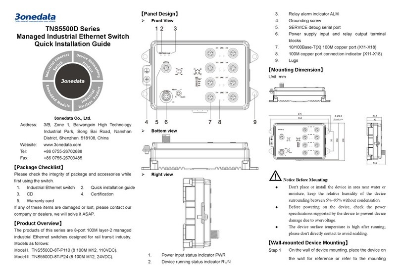
3One data IES5028-4GS User manual

3One data

3One data IES5028-4GS User manual

3One data IPS7112G-4GS-8GPOE User manual

3One data

3One data IPS7112G-4GS-8GPOE User manual

3One data IES6220 Series User manual

3One data

3One data IES6220 Series User manual

3One data IES1024 Series User manual

3One data

3One data IES1024 Series User manual

3One data IES618 Series User manual

3One data

3One data IES618 Series User manual

3One data ES209G-1GF User manual

3One data

3One data ES209G-1GF User manual

3One data ICS5530-16GS8GC6XS-2P220 User manual

3One data

3One data ICS5530-16GS8GC6XS-2P220 User manual

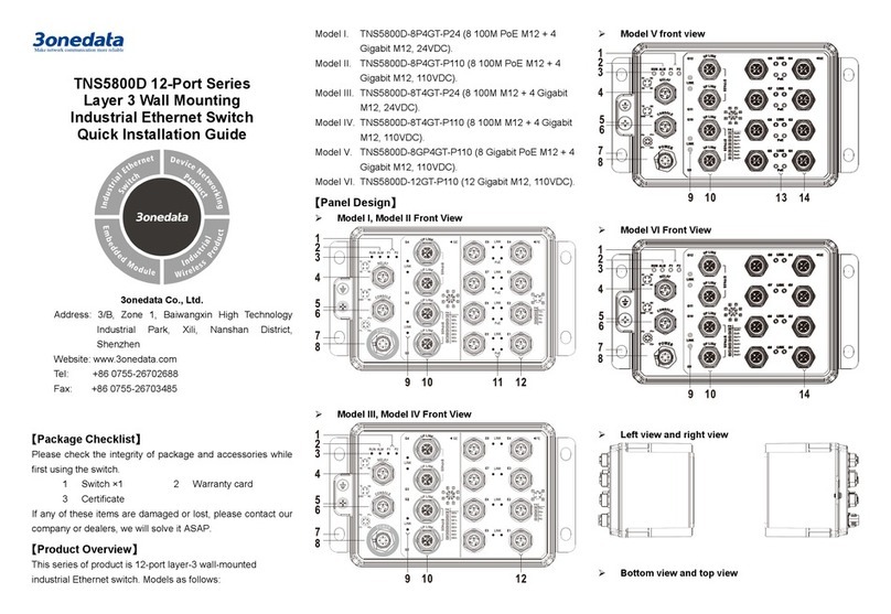
3One data TNS5800 Series User manual

3One data

3One data TNS5800 Series User manual

3One data IES6100PN-8T-2LV User manual

3One data

3One data IES6100PN-8T-2LV User manual

3One data IPS215 Series User manual

3One data

3One data IPS215 Series User manual

3One data IES6306 Series User manual

3One data

3One data IES6306 Series User manual

3One data ICS6420 Series User manual

3One data

3One data ICS6420 Series User manual

3One data ES5018 User manual

3One data

3One data ES5018 User manual

3One data IES3012G Series User manual

3One data

3One data IES3012G Series User manual

3One data IPS215 Series User manual

3One data

3One data IPS215 Series User manual

3One data IES716-2GS User manual

3One data

3One data IES716-2GS User manual

3One data IES7112G-4GS User manual

3One data

3One data IES7112G-4GS User manual

3One data IES615-2DI(3IN1) Series User manual

3One data

3One data IES615-2DI(3IN1) Series User manual

3One data IES5028G Series User manual

3One data

3One data IES5028G Series User manual

3One data PS5010G-2GS-8PoE User manual

3One data

3One data PS5010G-2GS-8PoE User manual

3One data IES618 Series User manual

3One data

3One data IES618 Series User manual

3One data ICS5400TSN-24GT16GS4XS-LN Series User manual
3One data

3One data ICS5400TSN-24GT16GS4XS-LN Series User manual

3One data IES6306 Series User manual

3One data

3One data IES6306 Series User manual

3One data IPS7112G-4GS-8GPOE User manual

3One data

3One data IPS7112G-4GS-8GPOE User manual

Popular Switch manuals by other brands

Juniper Day One+ manual

Juniper

Juniper Day One+ manual

HP FlexFabric 7900 Series Command reference

HP

HP FlexFabric 7900 Series Command reference

ANTAIRA LNX-C800 Series Hardware manual

ANTAIRA

ANTAIRA LNX-C800 Series Hardware manual

NetComm NP3016 Specifications

NetComm

NetComm NP3016 Specifications

H3C S5500-SI Series Operation manual

H3C

H3C S5500-SI Series Operation manual

Lantronix LSS2200-8P quick start guide

Lantronix

Lantronix LSS2200-8P quick start guide

PowerShield PSMBS2K quick guide

PowerShield

PowerShield PSMBS2K quick guide

Lantronix SM12XPA install guide

Lantronix

Lantronix SM12XPA install guide

Elko iNels RFSAI-62B-SL quick start guide

Elko

Elko iNels RFSAI-62B-SL quick start guide

ANTAIRA LNP-C501G-SFP-bt Series Hardware manual

ANTAIRA

ANTAIRA LNP-C501G-SFP-bt Series Hardware manual

Aastra ATP-CNX-020 Installation and setup guide

Aastra

Aastra ATP-CNX-020 Installation and setup guide

IOGear MiniView Extreme GCS1732 user manual

IOGear

IOGear MiniView Extreme GCS1732 user manual

Cisco 11154 - CSS - Switch datasheet

Cisco

Cisco 11154 - CSS - Switch datasheet

Brocade Communications Systems Brocade TurboIron 24 Series Hardware installation guide

Brocade Communications Systems

Brocade Communications Systems Brocade TurboIron 24 Series Hardware installation guide

Siemens SIRIUS 3SE6315 BB0 Series Original operating instructions

Siemens

Siemens SIRIUS 3SE6315 BB0 Series Original operating instructions

TFortis PSW-2G2F+UPS operating instructions

TFortis

TFortis PSW-2G2F+UPS operating instructions

Pulsar S94-CR Instruction

Pulsar

Pulsar S94-CR Instruction

Planet Networking & Communication IGS-6329 Series user manual

Planet Networking & Communication

Planet Networking & Communication IGS-6329 Series user manual

manuals.online logo
manuals.online logoBrands
  • About & Mission
  • Contact us
  • Privacy Policy
  • Terms and Conditions

Copyright 2025 Manuals.Online. All Rights Reserved.