manuals.online logo
Brands
  1. Home
  2. •
  3. Brands
  4. •
  5. BENDIX
  6. •
  7. Control Unit
  8. •
  9. BENDIX ATR1DC ANTILOCK TRACTION RELAY User manual

BENDIX ATR1DC ANTILOCK TRACTION RELAY User manual

1
Installation
Instructions
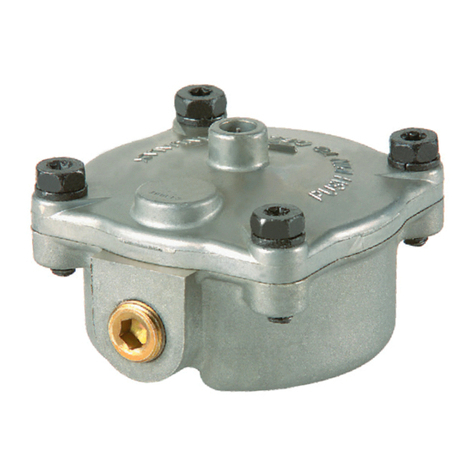
Replace Bendix®ATR‑1DC™Traction
Relay Valve with Bendix®R‑12DC®
Relay Valve and AT‑3™Traction Valve
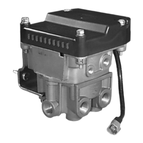
FIGURE 1 - BENDIX®ATR-6™TRACTION RELAY VALVE (WITH EXPLODED VIEW)
VEHICLE PREPARATION
Follow all standard industry safety precautions, including, but
not limited to, those listed on page two of these instructions.
1. Park the vehicle on a level surface and block the wheels
and/or hold the vehicle by means other than the air
brakes.
2. Drain the air pressure from all vehicle reservoirs.
REMOVAL
1. Prior to disassembly, remove as much contamination as
possible from the exterior of the device.
2. Identify and mark or label the electrical wiring harness
and air hoses and their respective connections on the
valve to aid the technician during reinstallation.
3. Disconnect air hoses from the Bendix®ATR‑1DC™traction
relay valve.
4. Disconnect the electrical connections.
5. Remove the mounting hardware bolts and then remove
the Electronic Control Unit (ECU) from the valve. (See
Figure 1).
6. Discard the original traction control valve body.
INSPECTION
1. Inspect the mounting location for deterioration, wear, and
corrosion. Replace and/or repair as necessary.
INSTALLATION
See the schematic diagrams on page 3 as you plan the
locations to install the replacement components. Take into
consideration the routing of the electrical harnesses, hoses
and orientation of the replacement valves and the remote
mounting of the ECU controller. Note that the schematics
show the new air lines (some indicated as 3/8 inch) that will
be required for this repair.
Note: All torques specied in this document are assembly
torques and can be expected to fall off slightly after assembly.
Do not re‑torque after initial assembly torques fall. For
assembly, use hand tools or torque limited drivers.
Do not use impact driver to install any ttings. Use a
professional grade thread sealant on all air lines connections
to the valves.
Kit Contents
Key No. Description
1. . . . . . R‑12DC®Relay Valve
2 . . . . . . AT‑3™Traction Valve
3. . . . . . Bracket (varies by kit)
4. . . . . . Adapter Harness (varies by kit)
Bendix®ATR-1DC™
traction relay valve
Adapter Harnesses
Vary by Kit
Through Holes
for Mounting
(2)
Electrical
Connector
Electronic Control
Unit (ECU)
Solenoid Body
Valve Body
Supply Port
1/4-18 NPT
Service Port
1/8-27 NPT
Traction Relay
Valve Body Delivery Port
1/4-18 NPT
Primary Control
Port 1/4 NPT
Secondary
Control Port
1/4 NPT
Vertical
Delivery Ports
Supply Port Bendix®R-12DC®
Relay Valve
(Horizontal Delivery
Port Version Shown)
Bendix®AT-3™
Traction Valve
(Two Views)
Bracket supplied
varies by kit
number
2
INSTALLATION OF BENDIX®AT-3™TRACTION VALVE
Bendix approves two methods of installation:
(a) either install the valve onto the vehicle with OEM
approved mounting bolts, and then attach the ttings, or,
(b) bench installation of the ttings, using only the clamp
location shown in Figure 3, before installing the valve on
the vehicle.
1. Clean and inspect all air lines and electrical harnesses
for damage and replace as necessary. Select one of the
two tting installation methods, either bolt the valve onto
the vehicle rst, or clamp, as shown in Figure 3, using a
bench vise.
GENERAL SAFETY GUIDELINES
WARNING! PLEASE READ AND FOLLOW
THESE INSTRUCTIONS TO AVOID
PERSONAL INJURY OR DEATH:
When working on or around a vehicle, the following
general precautions should be observed at all times.
1. Park the vehicle on a level surface, apply the
parking brakes, and always block the wheels.
Always wear safety glasses.
2. Stop the engine and remove ignition key when
working under or around the vehicle. When
working in the engine compartment, the engine
should be shut off and the ignition key should
be removed. Where circumstances require
that the engine be in operation, EXTREME
CAUTION should be used to prevent personal
injury resulting from contact with moving,
rotating, leaking, heated or electrically charged
components.
3. Do not attempt to install, remove, disassemble
or assemble a component until you have read
and thoroughly understand the recommended
procedures. Use only the proper tools and
obser ve all precautions per taining to use of those
tools.
4. If the work is being performed on the vehicle’s
air brake system, or any auxiliary pressurized air
systems, make certain to drain the air pressure
from all reservoirs before beginning ANY work
on the vehicle. If the vehicle is equipped with
an AD-IS®air dryer system or a dryer reservoir
module, be sure to drain the purge reservoir.
5. Following the vehicle manufacturer’s
recommended procedures, deactivate the
electrical system in a manner that safely removes
all electrical power from the vehicle.
6. Never exceed manufacturer’s recommended
pressures.
7. Never connect or disconnect a hose or line
containing pressure; it may whip. Never remove
a component or plug unless you are certain all
system pressure has been depleted.
8. Use only genuine Bendix®brand replacement
parts, components and kits. Replacement
hardware, tubing, hose, ttings, etc. must be of
equivalent size, type and strength as original
equipment and be designed specically for such
applications and systems.
9. Components with stripped threads or damaged
parts should be replaced rather than repaired.
Do not attempt repairs requiring machining or
welding unless specically stated and approved
by the vehicle and component manufacturer.
10. Prior to returning the vehicle to service, make
certain all components and systems are restored
to their proper operating condition.
11. For vehicles with Automatic Traction Control
(ATC), the ATC function must be disabled (ATC
indicator lamp should be ON) prior to performing
any vehicle maintenance where one or more
wheels on a drive axle are lifted off the ground
and moving.
FIGURE 3 ‑ VISE CLAMP LOCATION FOR BENCH
INSTALLATION OF FITTINGS
Permitted
Clamp
Location
Clamp From
Both Sides
of Mounting
Hole Flange
Permitted
Clamp
Location
Never Clamp
Using Solenoid
Body
FIGURE 2 ‑ THE BENDIX®AT-3™SOLENOID VALVE -
BAYONET CONNECTOR
Bayonet
(Twist-Lock)
Connector
2. With thread sealant applied, connect the (1/4‑18 NPT)
tting to the Supply and Delivery ports at an initial torque
of 15 ± 3 ft. lbs. The ttings may be oriented clockwise,
no more than one (1) additional turn to its nal position.
3
3. For vehicles where the service port is used, apply thread
sealant to the ttings and tighten to 18 ft. lbs. (25 N•m).
Where the ttings were installed using a bench vise, now
bolt the valve onto the vehicle.
4. Reconnect the wire harness to the solenoid using the
identication made during REMOVAL step. Be sure to
check that the harness has sufcient tie-wraps, etc. to
prevent any damage during vehicle operation.
5. Test valve as outlined in Operational and Leakage Tests.
INSTALLATION OF BENDIX®R-12DC®RELAY VALVE
1. In most cases, the brackets supplied in the kit will allow
the existing holes in the frame rail to be used. It will be
necessary to remove two of the relay valve's cap screws
to install the mounting bracket. Torque cap screws to
80‑100 inch pounds.
2. In cases where the bracket supplied does not include
mounting studs, install the bracket on the vehicle frame
using grade 5 mounting bolts.
3. Inspect all lines and/or hoses for damage and replace
as necessary.
4. Connect air lines to valve (plug any unused ports).
5. Test the valve as outlined in the Operational and Leakage
Test section before returning the valve to service.
1121
D
SD
S
41
D
S
41
S
D
SER
22
42
11
21
22
42
SD
S
FIGURE 4 ‑ SYSTEM SCHEMATICS
Bendix®ATR-1DC™
Traction Relay
Valve
Existing ECU
ECU ECU
Remote-Mount Existing ECU
With Connector Pointed
Down or Sideways Only
Bendix®AT-3™
Traction Valve
Existing ABS Modulator
SYSTEM SUPPLY TANK
(Reservoir)
SYSTEM SUPPLY TANK
(Reservoir)
Brake
Chamber
Brake
Chamber
3/8" Tubing
Bendix®R-12DC®
Relay Valve
Connector
Existing Lines
NOTE: Must comply with FMVSS 121 service brake
response time requirements.
Original System Schematic
Replacement System Schematic
4S-1532 © 2011 Bendix Commercial Vehicle Systems LLC 07/11 Printed in U.S.A. All Rights Reserved.
Bendix Technical Assistance Team
For direct telephone technical support, call the Bendix Tech Team at:
1-800-AIR-BRAKE (1-800-247-2725),
Monday through Friday, 8:00 A.M. to 6:00 P.M. EST, and follow the
instructions in the recorded message.
Or, you may e‑mail: [email protected]
Please have the following information ready when you call: Bendix product
model number, part number and conguration, vehicle make and model,
vehicle conguration (number of axles, tire size, etc.).
Reference:
The full Service Data sheet for the Bendix®ATR‑6™Traction Relay Valve is
SD‑13‑4861 (BW2598) and is available for download on www.bendix.com,
or you can order copies from the Literature Center at the website.
REMOTE-MOUNT OF EXISTING ELECTRONIC
CONTROL UNIT (ECU)
1. Select a suitable location on a frame rail so that the
existing harnesses can be used, bearing in mind any
vehicle manufacturer's guidelines for mounting holes.
Choose a location that is not subject to road‑spray. Note
that the ECU's connector must point either downwards or
sideways after installation to help prevent water entering
the electrical connectors.
2. Make a template of the four mounting holes for the ECU
and mark and drill the frame.
3. Mount the ECU using grade 5 bolts and nuts. Torque to
a maximum of 98 inch‑pounds.
OPERATIONAL AND LEAKAGE TESTS
1. Chock the wheels, fully charge air brake system and apply
the brakes.
2. Coat the valves with a soap solution; leakage of a one‑
inch bubble in 3 seconds is permitted. (Where the Service
Port is open to the atmosphere, do not spray the soap
solution directly into this port, or snorkel tube, where
installed.)
OPERATION TEST
Since this valve is used for different functions depending on
the vehicle, consult the vehicle Operator's Manual for further
information. Also, refer to the Antilock Traction Controller's
Service Data sheet (visit www.bendix.com) for operational
test(s) for traction functionality. In addition, for certain vehicle
air brake systems, a PC with the Bendix®ACom®Diagnostics
software may be used to test the valve.

Other manuals for ATR1DC ANTILOCK TRACTION RELAY

1

This manual suits for next models

2

Other BENDIX Control Unit manuals

BENDIX LQ-3 LQ-4 FRONT AXLE RATIO VALVE User manual

BENDIX

BENDIX LQ-3 LQ-4 FRONT AXLE RATIO VALVE User manual

BENDIX RV-1 PRESSURE REDUCING VALVE User manual

BENDIX

BENDIX RV-1 PRESSURE REDUCING VALVE User manual

BENDIX QR-L INLINE QUICK RELEASE VALVE User manual

BENDIX

BENDIX QR-L INLINE QUICK RELEASE VALVE User manual

BENDIX AR-2 ANTILOCK RELAY VALVE User manual

BENDIX

BENDIX AR-2 ANTILOCK RELAY VALVE User manual

BENDIX E-10 DUAL BRAKE VALVES User manual

BENDIX

BENDIX E-10 DUAL BRAKE VALVES User manual

BENDIX R-12V User manual

BENDIX

BENDIX R-12V User manual

BENDIX TP-3 TRACTOR PROTECTION VALVE User manual

BENDIX

BENDIX TP-3 TRACTOR PROTECTION VALVE User manual

BENDIX DV-2 Mounting instructions

BENDIX

BENDIX DV-2 Mounting instructions

BENDIX SC-3 INLINE SINGLE CHECK VALVES User manual

BENDIX

BENDIX SC-3 INLINE SINGLE CHECK VALVES User manual

BENDIX PP-DC PARK CONTROL VALVE User manual

BENDIX

BENDIX PP-DC PARK CONTROL VALVE User manual

BENDIX E-5 BRAKE VALVE User manual

BENDIX

BENDIX E-5 BRAKE VALVE User manual

BENDIX PP-1-2-5-8-RD-3 PUSH-PULL VALVES User manual

BENDIX

BENDIX PP-1-2-5-8-RD-3 PUSH-PULL VALVES User manual

BENDIX R-12-R-14 RELAY VALVES User manual

BENDIX

BENDIX R-12-R-14 RELAY VALVES User manual

BENDIX RE-4 RELAY EMERGENCY VALVE User manual

BENDIX

BENDIX RE-4 RELAY EMERGENCY VALVE User manual

BENDIX R-12P PILOT RELAY VALVE User manual

BENDIX

BENDIX R-12P PILOT RELAY VALVE User manual

BENDIX MV-1 MODUTROL Service manual

BENDIX

BENDIX MV-1 MODUTROL Service manual

BENDIX QRV QR-1 QUICK RELEASE VALVES Service manual

BENDIX

BENDIX QRV QR-1 QUICK RELEASE VALVES Service manual

BENDIX E-10P DUAL BRAKE VALVES User manual

BENDIX

BENDIX E-10P DUAL BRAKE VALVES User manual

BENDIX TP-3 Mounting instructions

BENDIX

BENDIX TP-3 Mounting instructions

BENDIX DOUBLE CHECK VALVES User manual

BENDIX

BENDIX DOUBLE CHECK VALVES User manual

BENDIX TC-7 TRAILER CONTROL BRAKE VALVE User manual

BENDIX

BENDIX TC-7 TRAILER CONTROL BRAKE VALVE User manual

BENDIX TP-4 TRACTOR PROTECTION VALVE User manual

BENDIX

BENDIX TP-4 TRACTOR PROTECTION VALVE User manual

BENDIX TP-2 TRACTOR PROTECTION VALVE User manual

BENDIX

BENDIX TP-2 TRACTOR PROTECTION VALVE User manual

BENDIX R-8 RELAY VALVE User manual

BENDIX

BENDIX R-8 RELAY VALVE User manual

Popular Control Unit manuals by other brands

ABB MRP31.0 manual

ABB

ABB MRP31.0 manual

getAir LED Installation & user guide

getAir

getAir LED Installation & user guide

Grundfos PM 1 Installation and operating instructions

Grundfos

Grundfos PM 1 Installation and operating instructions

Pilz PSS u2 ES 8DI operating manual

Pilz

Pilz PSS u2 ES 8DI operating manual

Moog 631 Series Installation and operation instruction

Moog

Moog 631 Series Installation and operation instruction

Samson 3244-1 Mounting and operating instructions

Samson

Samson 3244-1 Mounting and operating instructions

Pickering 41-670 manual

Pickering

Pickering 41-670 manual

Allen-Bradley ControlLogix 1756-ENBT user manual

Allen-Bradley

Allen-Bradley ControlLogix 1756-ENBT user manual

BRAHMA SR3 quick start guide

BRAHMA

BRAHMA SR3 quick start guide

Flowserve Argus Series Operation instructions

Flowserve

Flowserve Argus Series Operation instructions

PROEL PC260 user manual

PROEL

PROEL PC260 user manual

Zator MZB200 User and maintenance manual

Zator

Zator MZB200 User and maintenance manual

LUMILEDS LUXEON MultiColor Module 2.5W Assembly and Handling Information

LUMILEDS

LUMILEDS LUXEON MultiColor Module 2.5W Assembly and Handling Information

Telit Wireless Solutions ME910C1 Series user guide

Telit Wireless Solutions

Telit Wireless Solutions ME910C1 Series user guide

GE RX3i PROFINET quick start guide

GE

GE RX3i PROFINET quick start guide

Sony RM-450 Service manual

Sony

Sony RM-450 Service manual

mikroElektronika click BOARD IR reflect click manual

mikroElektronika

mikroElektronika click BOARD IR reflect click manual

Honeywell VHL120 Installation and user instructions

Honeywell

Honeywell VHL120 Installation and user instructions

manuals.online logo
manuals.online logoBrands
  • About & Mission
  • Contact us
  • Privacy Policy
  • Terms and Conditions

Copyright 2025 Manuals.Online. All Rights Reserved.