manuals.online logo
Brands
  1. Home
  2. •
  3. Brands
  4. •
  5. BENDIX
  6. •
  7. Control Unit
  8. •
  9. BENDIX QR-1C DBL CHECK QUICK RELEASE VALVE User manual

BENDIX QR-1C DBL CHECK QUICK RELEASE VALVE User manual

1
FIGURE A
SD-03-904
DESCRIPTION
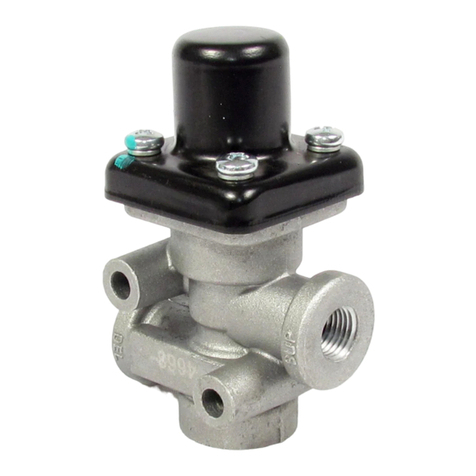
The Bendix®QR-1C™is a dual function valve. The valve’s
primaryfunctionistoservetheemergencysideofaspring
brake actuator as a quick release valve. In addition, it
functions as an anti-compound device. The double check
valvepreventsaserviceandemergencybrakeapplication
fromoccurringsimultaneously.
The QR-1C™valve is generally mounted on the axle and
serves two spring brake actuators. The air connections to
theQR-1C™valveareasfollows:
1. QR-1C™valvedelivery port(2)connected toemergency
portofspring brake.
2. QR-1C™valvebalanceport(1) connected to deliveryof
brakevalveorrelayvalve.NOTE:Ifrelayvalveisinstalled
on vehicle, it should be connected to the delivery side
(notserviceorsignalside).
3. QR-1C™valve supply port (1) connected to delivery of
parkcontrolvalve.
Inits standard configurationthevalveis designed todeliver
within 1 psi of control pressure. However, for special
applications the valve is available with greater differential
pressureor zerohysteresis.QR-1C™valves alsocomewith
optional noise reducing foam crosses or silencers. Some
QR-1C™valves can also come with biased double check
valves. These double check valves contain a beaded seat
capnut(FigureB).Thebiasdesignminimizeslowdifferential
leakage.
Bendix®QR-1C™Double Check and Quick Release Valve
MountingHoles
Delivery(2)
Supply
Port(1)
Body
QuickRelease
Diaphragm
Delivery
SealingRing
Exhaust
Cover
SealingRing
DoubleCheck
Diaphragm BalancePort(1)
CapNut
Beaded
(Biased)Seat
Non-Beaded
Identification
Mark
FIGURE B
2
OPERATION
SPRING BRAKES RELEASED
Whenthespringbrakesarereleased,airfromtheparkcontrol
valveflowsthrough the QR-1C™valve, causing the double
checkvalveandquickreleasediaphragmstoflexandseal
thebalance andexhaustports.Air flowsintothe emergency
port of the spring brakes from the QR-1C™valve delivery
ports.
SPRING BRAKES APPLIED
Whenthespringbrakes areapplied, supplyline airpressure
tothevalve is exhausted through the parkcontrol valve.As
air pressure is removed from one side of the double check
valveandquickreleasediaphragms,theyflexintheopposite
directionopeningthebalanceandexhaustports.Springbrake
emergency pressure is released at the exhaust port of the
valvewhile thesmallamount ofairtrapped betweenthe two
diaphragmsisreleasedthroughtherelayvalveorbrakevalve
exhaust.
ANTI-COMPOUNDING
When a service brake application is made with the spring
brakesapplied,serviceair entersthe balanceportandflows
through the valve into the emergency ports of the spring
brakes. This prevents the compounding of a service and
spring brake application. Service air passing through the
valveflexesthedoublecheckandquickreleasediaphragms,
sealing the supply and exhaust ports. When the service
application is released, air is exhausted from the spring
brakes.
PREVENTIVE MAINTENANCE
Important: Review the Bendix Warranty Policy before
performinganyintrusivemaintenanceprocedures.Awarranty
maybe voided ifintrusivemaintenance is performedduring
thewarranty period.
No two vehicles operate under identical conditions, as a
result, maintenance intervals may vary. Experience is a
valuableguide indetermining thebestmaintenance interval
for air brake system components. At a minimum, the
QR-1C™valveshouldbeinspectedevery 12monthsor3600
operatinghours,whichever comesfirst,forproperoperation.
Should the QR-1C™valve not meet the elements of the
operationaltestsnotedinthisdocument,further investigation
andservice of thevalvemay berequired.
REMOVAL
1. Blockvehicle wheelsand/or holdvehiclebymeansother
thanairbrakes.
2. Drainallairbrakesystem reservoirs.
3. Identifyand disconnect air linesfromvalve.
4. Removemounting bolts,thenvalve.
DISASSEMBLY
Marktherelationshipofthebodyandcoverbeforedisassembly.
1. Removecap nut.
2. Removesealing ring from capnut.
3. Removedouble checkvalve diaphragm.
4. Removefour Phillips headscrews.
5. Separate the body and cover and remove the sealing
ringand quick release diaphragm.
CLEANING AND INSPECTION
Cleanall metal partsinmineral spirits.Wipeall rubber parts
clean.It isrecommendedthat allrubberparts andanyother
partshowing signsofwear ordeteriorationbe replacedwith
genuineBendixparts.
ASSEMBLY
1. Install sealing ring on cap nut.
2. Installdouble check valvediaphragmin body.
3. Installcap nut and torque to 150-400 inch pounds.
4. Installsealing ring invalvebody.
5. Installthe quick release diaphragm in the cover.
6. Install the cover and diaphragm on body, aligning the
marksmade duringdisassembly.Securetogetherusing
the four Phillips head screws and torque to 30-60 inch
pounds.
7. Re-installtheQR-1C™valveandbeforeputtingthevehicle
inservice, perform the “Operation andLeakageTests.”
OPERATING AND LEAKAGE TESTS
Before performing these tests, park the vehicle on a level
surfaceandholdthevehiclebymeansotherthanthebrakes.
1. Withthe parkcontrolvalve inthereleased position,note
thatthespringbrakesarereleased.
2. Remove the air line connected to the QR-1C™valve
balance port and apply a soap solution to the exhaust
andbalanceport.A1"bubblein5secondsispermissible
at either location.
3. Reconnect the QR-1C™valve balance line; and using
theparkcontrolvalve,parkthe vehicle.NOTE:Aprompt
applicationof the springbrakeswithan exhaust ofairat
theQR-1C™valve exhaustport.
4. Remove the air line connected to the supply port of the
QR-1C™valve. With a service brake application hold
applied, apply a soap solution to the supply port and
aroundtheseambetweenthebodyandcover.A1"bubble
in 5 seconds is permissible at the supply port. No
leakageispermitted between the body and cover.
5. Reconnect the supply port air line. If the valve does not
function as described, or if leakage is excessive, it is
recommended that it be replaced with a new or
remanufacturedunit,orrepairedwithgenuineBendixparts.
3
INSTALLATION
Mountvalvewithexhaustportpointingdown;securelytighten
mounting bolts. Reconnect air lines as identified during
removal.
GENERAL SAFETY GUIDELINES
WARNING! PLEASE READ AND FOLLOW
THESE INSTRUCTIONS TO AVOID
PERSONAL INJURYOR DEATH:
When working on or around a vehicle, the following
general precautions should be observed at all times.
1. Park the vehicle on a level surface, apply the
parking brakes, and always block the wheels.
Always wear safety glasses.
2. Stop the engine and remove ignition key when
working under or around the vehicle. When
working in the engine compartment, the engine
should be shut off and the ignition key should be
removed. Where circumstances require that the
engine be in operation, EXTREME CAUTION should
be used to prevent personal injury resulting from
contact with moving, rotating, leaking, heated or
electrically charged components.
3. Do not attempt to install, remove, disassemble or
assemble a component until you have read and
thoroughly understand the recommended
procedures. Use only the proper tools and observe
all precautions pertaining to use of those tools.
4. If the work is being performed on the vehicle’s air
brake system, or any auxiliary pressurized air
systems,make certain to drain theair pressurefrom
all reservoirs before beginning ANY work on the
vehicle. If the vehicle is equipped with an AD-IS®
air dryer system or a dryer reservoir module, be
sure to drain the purge reservoir.
5. Following the vehicle manufacturer’s
recommended procedures, deactivate the electrical
systemin amanner that safely removes all electrical
power from the vehicle.
6. Never exceed manufacturer’s recommended
pressures.
7. Never connect or disconnect a hose or line
containing pressure; it may whip. Never remove a
componentor plugunless youare certainall system
pressure has been depleted.
8. Use only genuine Bendix®replacement parts,
components and kits. Replacement hardware,
tubing,hose, fittings,etc. mustbe of equivalent size,
type and strength as original equipment and be
designed specifically for such applications and
systems.
9. Components with strippedthreadsor damaged parts
should be replaced rather than repaired. Do not
attempt repairs requiring machining or welding
unless specifically stated and approved by the
vehicle and component manufacturer.
10.Prior to returning the vehicle to service, make
certain all components and systems are restored to
their proper operating condition.
11. For vehicles with Antilock Traction Control (ATC),
the ATC function must be disabled (ATC indicator
lamp should be ON) prior to performing any vehicle
maintenance where one or more wheels on a drive
axle are lifted off the ground and moving.
4BW1585 © 2006 Bendix Commercial Vehicle Systems LLC. All rights reserved. 7/2006 Printed in U.S.A.

This manual suits for next models

1

Other BENDIX Control Unit manuals

BENDIX EVERFLOW User manual

BENDIX

BENDIX EVERFLOW User manual

BENDIX LQ-5 BOBTAIL RATIO VALVE User manual

BENDIX

BENDIX LQ-5 BOBTAIL RATIO VALVE User manual

BENDIX TC-2 TRAILER CONTROL BRAKE VALVE User manual

BENDIX

BENDIX TC-2 TRAILER CONTROL BRAKE VALVE User manual

BENDIX TIM G2 User manual

BENDIX

BENDIX TIM G2 User manual

BENDIX QRN-2 QUICK RELEASE VALVE User manual

BENDIX

BENDIX QRN-2 QUICK RELEASE VALVE User manual

BENDIX SC-3 INLINE SINGLE CHECK VALVES User manual

BENDIX

BENDIX SC-3 INLINE SINGLE CHECK VALVES User manual

BENDIX QR-L INLINE QUICK RELEASE VALVE User manual

BENDIX

BENDIX QR-L INLINE QUICK RELEASE VALVE User manual

BENDIX TABS-6 TRAILER ABS MODULE User manual

BENDIX

BENDIX TABS-6 TRAILER ABS MODULE User manual

BENDIX E-10PR RETARDER CTRL BRAKEVALVE User manual

BENDIX

BENDIX E-10PR RETARDER CTRL BRAKEVALVE User manual

BENDIX RV-4 PRESSURE REDUCING VALVE Operating and maintenance instructions

BENDIX

BENDIX RV-4 PRESSURE REDUCING VALVE Operating and maintenance instructions

BENDIX PP-7 TRAILER SUPPLY VALVE User manual

BENDIX

BENDIX PP-7 TRAILER SUPPLY VALVE User manual

BENDIX ST-1 User manual

BENDIX

BENDIX ST-1 User manual

BENDIX AR-1 ANTILOCK RELAY VALVE User manual

BENDIX

BENDIX AR-1 ANTILOCK RELAY VALVE User manual

BENDIX TW-2 User manual

BENDIX

BENDIX TW-2 User manual

BENDIX E-10 Mounting instructions

BENDIX

BENDIX E-10 Mounting instructions

BENDIX SR-2 TRAILER SPRING BRAKE VALVE User manual

BENDIX

BENDIX SR-2 TRAILER SPRING BRAKE VALVE User manual

BENDIX M-40QR Mounting instructions

BENDIX

BENDIX M-40QR Mounting instructions

BENDIX PRESSURE PROTECTION VALVES User manual

BENDIX

BENDIX PRESSURE PROTECTION VALVES User manual

BENDIX E-7 DUAL BRAKE VALVE User manual

BENDIX

BENDIX E-7 DUAL BRAKE VALVE User manual

BENDIX R-8 RELAY VALVE User manual

BENDIX

BENDIX R-8 RELAY VALVE User manual

BENDIX E-5 BRAKE VALVE User manual

BENDIX

BENDIX E-5 BRAKE VALVE User manual

BENDIX R-7 MODULATING VALVE User manual

BENDIX

BENDIX R-7 MODULATING VALVE User manual

BENDIX SR-5 TRAILER SPRING BRK VALVE User manual

BENDIX

BENDIX SR-5 TRAILER SPRING BRK VALVE User manual

BENDIX E-14 DUAL BRAKE VALVE User manual

BENDIX

BENDIX E-14 DUAL BRAKE VALVE User manual

Popular Control Unit manuals by other brands

Watts LFM127-8 Installation, operation and maintenance

Watts

Watts LFM127-8 Installation, operation and maintenance

RF-Star RF-BM-2652B1 manual

RF-Star

RF-Star RF-BM-2652B1 manual

Sony CCU-50P Operation instructions

Sony

Sony CCU-50P Operation instructions

Erica Synths HI-HATS A manual

Erica Synths

Erica Synths HI-HATS A manual

AMES 910GD-01 Installation, operation and maintenance

AMES

AMES 910GD-01 Installation, operation and maintenance

Rockwell Automation Allen-Bradley PowerFlex 750 ATEX Series user manual

Rockwell Automation

Rockwell Automation Allen-Bradley PowerFlex 750 ATEX Series user manual

Dynojet Power Commander FC installation instructions

Dynojet

Dynojet Power Commander FC installation instructions

Schmidt MV3 Operation and maintenance manual

Schmidt

Schmidt MV3 Operation and maintenance manual

Sony FCB-EV7300 Technical manual

Sony

Sony FCB-EV7300 Technical manual

FS EM-3 installation instructions

FS

FS EM-3 installation instructions

Lenze 8400 motec E84DGFC Series Mounting instructions

Lenze

Lenze 8400 motec E84DGFC Series Mounting instructions

Allen-Bradley Entek XM-123 user guide

Allen-Bradley

Allen-Bradley Entek XM-123 user guide

Watts Industries PR500 instruction manual

Watts Industries

Watts Industries PR500 instruction manual

SYR 315 Instructions for use

SYR

SYR 315 Instructions for use

Armstrong GP-2000 Installation, operation and maintenance

Armstrong

Armstrong GP-2000 Installation, operation and maintenance

Transition Networks SAPTF33-1 Series user guide

Transition Networks

Transition Networks SAPTF33-1 Series user guide

Booma-RC Intellimatch IM22 quick start guide

Booma-RC

Booma-RC Intellimatch IM22 quick start guide

Comizoa ETS-DI32N-T Hardware reference manual

Comizoa

Comizoa ETS-DI32N-T Hardware reference manual

manuals.online logo
manuals.online logoBrands
  • About & Mission
  • Contact us
  • Privacy Policy
  • Terms and Conditions

Copyright 2025 Manuals.Online. All Rights Reserved.