manuals.online logo
Brands
  1. Home
  2. •
  3. Brands
  4. •
  5. BENDIX
  6. •
  7. Control Unit
  8. •
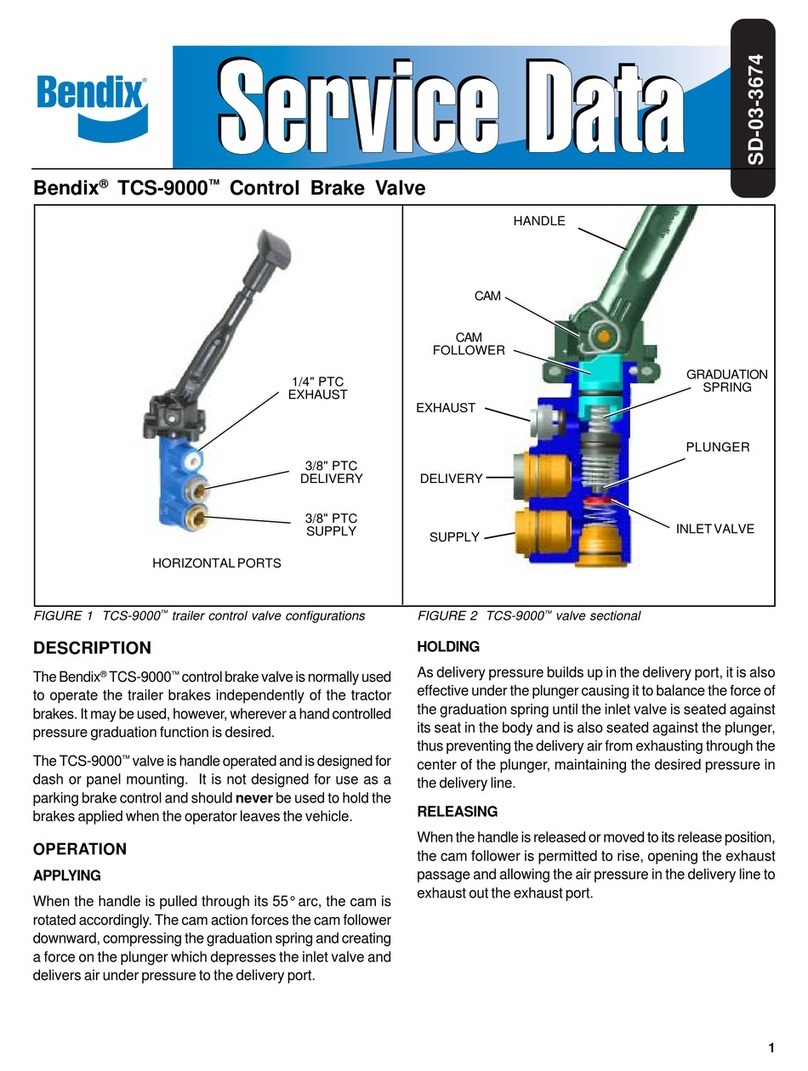
  9. BENDIX TW-12 CONTROL VALVE User manual

BENDIX TW-12 CONTROL VALVE User manual

1
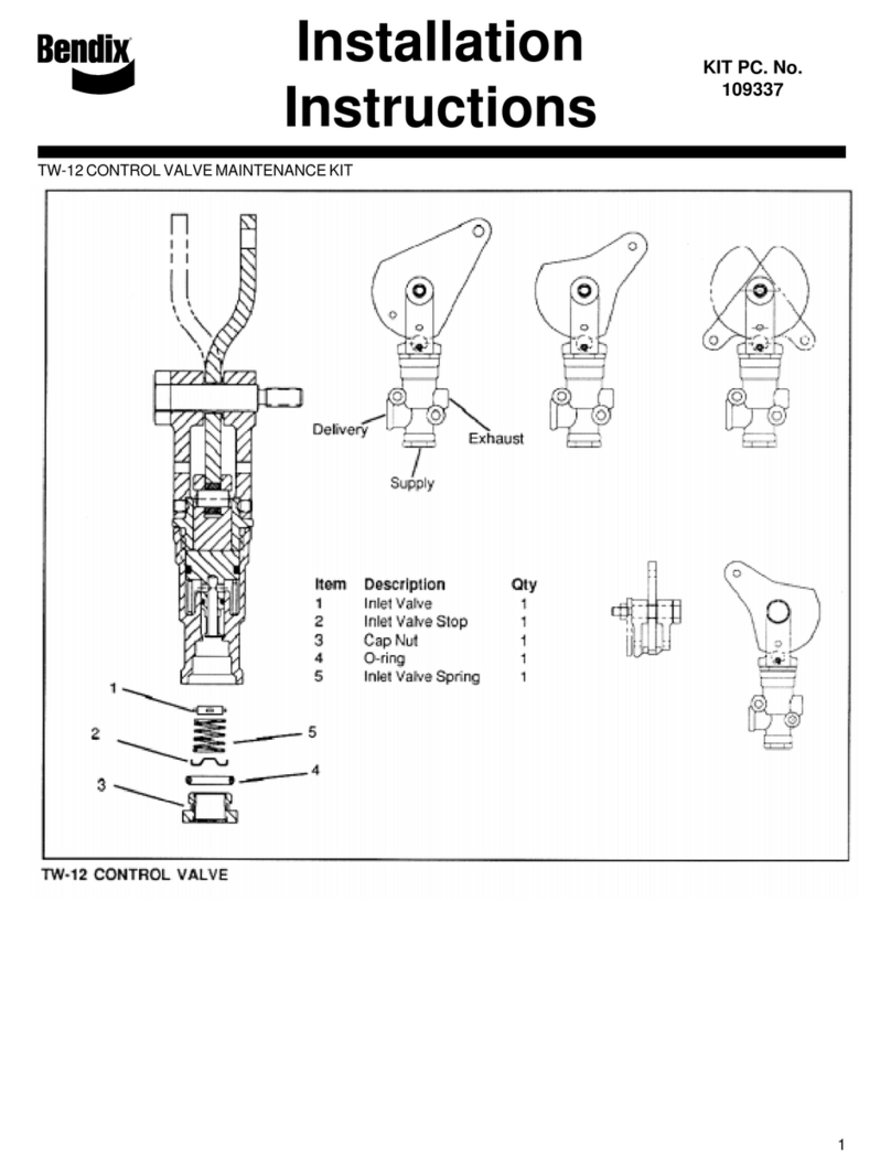
DESCRIPTION
The TW-12™ control valve is a manually operated, non-
graduating, on-off valve. It is extensively used in hydraulic
braking systems to control devices that are responsible for
the application and release of the parking brakes.
Note: The TW-12™control valve can also be
used in air brake system applications.
ThemostcommonconfigurationoftheTW-12™controlvalve
uses a levered cam that is manually, remote controlled. A
dash mounted lever or button may be connected to the
aluminumlevercamvia Bowdencablecontrolor connected
directly to the transmission selector.
Two .28 inch mounting holes are provided in the die cast
zinc body for panel or frame mounting. Two steel hex cap
nutsattheendsofthecylindricalvalvebodyretaintheinternal
components and provide attachment for the lever cam.All
connection ports are pipe threads. Lettering embossed in
the valve body identifies two of the three ports in the valve.
Referto thefollowing chartand figureone.
Connection Body Ident. Thread Sizex
Supply SUP 1/4" P.T. xx
Delivery DEL 1/4" P.T. xx
Vent NONE 1/8" P.T. xx
OPERATION
SYSTEM CONNECTIONS
AlthoughtheTW-12™valvecanbeusedinavarietyofdifferent
systemsandconnected in differentways,figure 2illustrates
a typical hydraulic parking brake system. In this system
the TW-12™valve controls an HR-1™hydraulic relay that in
turn applies and releases hydraulic spring brakes.
VALVE OPERATION
Parking Brakes Applied
Withhydraulic fluid flowing to thesupply port(Figure 1)and
thepiston inthe upwardposition, fluidflow intothe TW-12™
control valve is stopped at the closed inlet valve.
FIGURE 1- TW-12TM CONTROL VALVE
PLUNGER
1/4" P.T.
DELIVERY
PORT
1/4" P.T. SUPPLY
PORT
LEVER CAM
INLET VALVE
LEVER
PIVOT
INLET VALVE SPRING
PISTON RETURN
SPRING
LEVER
YOKE
DELIVERY PORT
SUPPLY PORT
RETURN PORT
MOUNTING
HOLE (2)
1/8" P.T.
RETURN
PORT
LEVER
CAM
PISTON RETURN
PASSAGE
SUPPLY PORT
CAP NUT
CAP NUT O-RING
CONTROL
CABLE
CONNECTION
LEVER
YOKE
CAM
FOLLOWER
LEVER CAM
PIVOT
PISTON
PISTON O-RING
CAP
NUT
SD-03-3625
Bendix®TW-12™Control Valve
2
The TW-12™valve delivery port is open to its return port
through a passage in the center of the piston.
Parking Brakes Released
WhentheTW-12™control valveplungerisdepressedby the
cam action of the lever (Figure 1) the piston contacts the
inlet valve, closing the return passage. Continued piston
movement pushes the inlet valve off its seat in the body,
allowinghydraulicfluid toflow through thevalve andout the
deliveryport.
SERVICE CHECKS
GENERAL
Read the "General Safety Guidelines" presented in this
manual before beginning any testing or service procedure.
Withthe TW-12™control valveinstalled inthe vehicle brake
system,propervalveoperation canonlybe observed bythe
reaction of the system and components controlled by the
TW-12™ valve.Ifmalfunctionorinternalleakageissuspected
or specific operational and leakage testing is desired, the
TW-12™ valve must be removed and bench tested. Bench
testing of the TW-12™ valve is accomplished using air
pressure regardless of its application or the braking media
used in the vehicle brake system.
OPERATING AND LEAKAGE TESTS
Function test the TW-12™ valve while it is installed in the
systembystartingtheengineandwarmingthevehiclebrake
systemfor5minutes. Move thelevercamfrom one extreme
position to the other three times and observe that the
componentscontrolledbytheTW-12™controlvalvefunction
promptlyto the ONthen OFFcondition. Inspect theexterior
of the TW-12™ valve. If the TW-12™ valve is used to control
hydraulic brakes, no fluid leakage should be noted. Pay
particularattentiontothearea around andbeneaththelever
cam.
1. Whenbench testing the TW-12™control valve, attach a
small reservoir volume to the delivery port with an air
gaugeinstalled.
Note: 6-8 feet of ½” tubing or hose could be
used in lieu of a small reservoir.
2. Apply a 120psi air pressure source to the supply port
and move the lever cam to the applied and released
position three times. Note that delivered air pressure is
the same as supply air pressure in the applied position
and that air is promptly exhausted in the released
position.
3. With the TW-12™control valve in the released position
and 120psi at the supply port, apply a soap solution to
the return port and around the supply port cap nut.
Leakage should not exceed a 1” bubble in less than 5
seconds (100 SCCM) at the return port. No leakage is
permitted at the cap nut.
4. Placethevalve in theapplied position andagainapply a
soap solution to the return port. Leakage should not
exceeda 1” bubble in less than 5 seconds (100 SCCM)
at the return port.
FIGURE 2 - TW-12™CONTROL VALVE HYDRAULIC PARK SYSTEM
POWER
STEERING
GEAR
HYDRAULIC
RESERVOIR
POWER
STEERING
PUMP
HR-1™
HYDRAULIC
RELAY
TW-12™
CONTROL
VALVE
MASTER
CYLINDER
HYDRAULIC
BRAKE
BOOSTER
HYDRAULIC
SPRING BRAKE
ACTUATOR
HYDRAULIC
SPRING BRAKE
ACTUATOR
OUT
RETURN
RETURN
RETURN
RETURN
OUT
SUPPLY
DELIVERY
TO SERVICE
BRAKES
CONTROL
DELIVERY DELIVERY
SUPPLY
IN
IN
IN
OUT
IN
3
5. With 120psi applied to the supply and return ports
simultaneously,applyasoapsolutionaroundtheplunger
andcamfollowerintheyoke assembly. Leakageshould
not exceed a 1” bubble in less than 5 seconds (100
SCCM).
If the TW-12™valve does not function as described or if
excessiveleakage isdetected, itis recommended that it be
replacedwith agenuine Bendix®service replacement.
PREVENTIVE MAINTENANCE
Important: Review the Bendix Warranty Policy before
performinganyintrusivemaintenanceprocedures. Awarranty
maybe voided ifintrusive maintenanceis performed during
thewarranty period.
No two vehicles operate under identical conditions, as a
result, maintenance intervals may vary. Experience is a
valuableguideindetermining thebestmaintenance interval
for system components.At a minimum the TW-12™valves
shouldbeinspectedevery6monthsor1500operatinghours,
whichevercomes first.
1. ChecktheTW-12™controlvalve forproperoperation.
2. Inspecttheexterior ofthe valve forsigns ofleakage and
any apparent physical damage.
3. Inspect the control cable and its connection point to the
levercamfor damage andwear.
Ifthe TW-12™controlvalve doesnot functionas required or
if leakage excessive, wear, or damage is noted during
inspection,replacethevalvewith a genuineBendix®service
replacementunit.
GENERAL SAFETY GUIDELINES - WARNING!
PLEASE READ AND FOLLOW THESE
INSTRUCTIONS TO AVOID PERSONAL
INJURY OR DEATH:
Whenworkingonoraroundbrakesystemsandcomponents,
the following precautions should be observed at all times:
1. Park the vehicle on a level surface, apply the parking
brakes, and always block the wheels. When working
aroundorunder thevehicle,stoptheengineandremove
the key from the ignition. Always keep hands away
from chambers as they may apply as system pressure
drops. Always wear safety glasses.
2. When working in the engine compartment, the engine
should be shut off and the ignition key should be
removed. Wherecircumstancesrequirethattheengine
be in operation, EXTREME CAUTION should be used
to prevent personal injury resulting from contact with
moving,rotating,leaking, heated orelectricallycharged
components.
3. Do not attempt to install, remove, disassemble or
assemble a component until you have read and
thoroughly understand the recommended procedures.
Use only the proper tools and observe all precautions
pertaining to the use of those tools.
4. Following the vehicle manufacturer’s recommended
procedures,deactivatetheelectricalsysteminamanner
thatsafelyremovesallelectricalpower from the vehicle.
5. Ifthevehicleisequippedwithanairoverhydraulicbrake
system or any auxiliary pressurized air system, make
certaintodrainthe air pressurefromallreservoirsbefore
beginning ANY work on the vehicle. If the vehicle is
equipped with an AD-IS®air dryer system or a dryer
reservoirmodule,be sureto drainthepurge reservoir.
6. Never connect or disconnect a hose or line containing
pressure; it may whip. Never remove a component or
pipe plug unless you are certain all system pressure
hasbeen depleted.
7. Neverexceedmanufacturer’s recommended pressure.
8. Never attempt to disassemble a component until you
havereadandunderstandallrecommendedprocedures.
Some components contain powerful springs and injury
canresultifnotproperly disassembled. Useonlyproper
tools and observe all precautions pertaining to use of
those tools.
9. Use only genuine Bendix®replacement parts,
components and kits.
A. Use only components, devices and mounting and
attaching hardware specifically designed for use
in hydraulic brake systems.
B. Allreplacementhardware,tubing,hose,fittings,etc.
must be of equivalent size, type and strength as
theoriginal equipment.
10. Components with stripped threads or damaged parts
shouldbereplacedrather than repaired.Donotattempt
repairsrequiringmachiningorweldingunlessspecifically
stated and approved by the vehicle and component
manufacturer.
11. Priorto returningthevehicle to service,make certain all
components and systems are restored to their proper
operatingcondition.
VALVE REMOVAL
1. Parkthevehicle onalevel surfaceandblock thewheels
and/orhold the vehicle by meansother thanthe service
brakes.
2. Remove pressure from the vehicle service and parking
brake system. In the case of a hydraulic brake system
consult the vehicle manual for proper procedures to be
followed.
3. Identify and mark or label all lines and their respective
connectionsonthevalve to facilitateeaseofinstallation.
4
4. Disconnectall linesand thecontrol cablefrom thelever
cam.
5. Removethevalvefromthe vehicle.
VALVE INSTALLATION
1. Install all line fittings and plugs making certain thread
sealing material, if used, does not enter the valve.
2. Installthe valve onthe vehicle.
3. Reconnect all lines to the valve using the identification
madeduringVALVEREMOVAL(step3).Reconnect the
control cable to the lever cam.
4. After installing the valve, test all fittings for excessive
leakage and tighten as needed.
5. Perform operational and leakage inspections prior to
returningthevehicletoservice.Inthecaseof a hydraulic
brake system consult the vehicle manual for proper
proceduresto be followed.
BW2578 © 2006 Bendix Commercial Vehicle Systems LLC. 6/2006 Printed in U.S.A. All rights reserved.

Other BENDIX Control Unit manuals

BENDIX ST-1 User manual

BENDIX

BENDIX ST-1 User manual

BENDIX ATR1DC ANTILOCK TRACTION RELAY User manual

BENDIX

BENDIX ATR1DC ANTILOCK TRACTION RELAY User manual

BENDIX PP-1-2-5-8-RD-3 PUSH-PULL VALVES User manual

BENDIX

BENDIX PP-1-2-5-8-RD-3 PUSH-PULL VALVES User manual

BENDIX TP-3 Mounting instructions

BENDIX

BENDIX TP-3 Mounting instructions

BENDIX QR-L INLINE QUICK RELEASE VALVE User manual

BENDIX

BENDIX QR-L INLINE QUICK RELEASE VALVE User manual

BENDIX BP-R1 BOBTAIL PROP RELAY VALVE User manual

BENDIX

BENDIX BP-R1 BOBTAIL PROP RELAY VALVE User manual

BENDIX PR-3 User manual

BENDIX

BENDIX PR-3 User manual

BENDIX R-12DC DBL CHECK RELAY VALVE User manual

BENDIX

BENDIX R-12DC DBL CHECK RELAY VALVE User manual

BENDIX LQ-3 LQ-4 FRONT AXLE RATIO VALVE User manual

BENDIX

BENDIX LQ-3 LQ-4 FRONT AXLE RATIO VALVE User manual

BENDIX AR-2 ANTILOCK RELAY VALVE User manual

BENDIX

BENDIX AR-2 ANTILOCK RELAY VALVE User manual

BENDIX INLET REG VALVE COMP User manual

BENDIX

BENDIX INLET REG VALVE COMP User manual

BENDIX ATR1DC ANTILOCK TRACTION RELAY User manual

BENDIX

BENDIX ATR1DC ANTILOCK TRACTION RELAY User manual

BENDIX MV-1 MODUTROL Service manual

BENDIX

BENDIX MV-1 MODUTROL Service manual

BENDIX TC-7 TRAILER CONTROL BRAKE VALVE User manual

BENDIX

BENDIX TC-7 TRAILER CONTROL BRAKE VALVE User manual

BENDIX M-40QR Mounting instructions

BENDIX

BENDIX M-40QR Mounting instructions

BENDIX E-5 BRAKE VALVE User manual

BENDIX

BENDIX E-5 BRAKE VALVE User manual

BENDIX SC-3 INLINE SINGLE CHECK VALVES User manual

BENDIX

BENDIX SC-3 INLINE SINGLE CHECK VALVES User manual

BENDIX SR-4 SPRING BRAKE CONTROL VLV User manual

BENDIX

BENDIX SR-4 SPRING BRAKE CONTROL VLV User manual

BENDIX TIM G2 User manual

BENDIX

BENDIX TIM G2 User manual

BENDIX BP-1 BRAKE PROPORTIONING VALVES User manual

BENDIX

BENDIX BP-1 BRAKE PROPORTIONING VALVES User manual

BENDIX LQ-5 BOBTAIL RATIO VALVE User manual

BENDIX

BENDIX LQ-5 BOBTAIL RATIO VALVE User manual

BENDIX E-12-E-15 BRAKE VALVE User manual

BENDIX

BENDIX E-12-E-15 BRAKE VALVE User manual

BENDIX TP-2 TRACTOR PROTECTION VALVE User manual

BENDIX

BENDIX TP-2 TRACTOR PROTECTION VALVE User manual

BENDIX DUAL RELAY VALVE User manual

BENDIX

BENDIX DUAL RELAY VALVE User manual

Popular Control Unit manuals by other brands

Air Lift QuickShot 25690 installation guide

Air Lift

Air Lift QuickShot 25690 installation guide

Delta DVP04TC-S instruction sheet

Delta

Delta DVP04TC-S instruction sheet

B+K precision MDL Series user manual

B+K precision

B+K precision MDL Series user manual

SimCom SIM800C Hardware design

SimCom

SimCom SIM800C Hardware design

Hobby-Wing WiFi Express HW30503000 user manual

Hobby-Wing

Hobby-Wing WiFi Express HW30503000 user manual

Pocket home PH-BHD operating instructions

Pocket home

Pocket home PH-BHD operating instructions

KEBCO COMBIVERT G6 series Programming manual

KEBCO

KEBCO COMBIVERT G6 series Programming manual

Qcells Q.SMART Series Installation and operation manual

Qcells

Qcells Q.SMART Series Installation and operation manual

SPX FLOW APV DELTA RG4 instruction manual

SPX FLOW

SPX FLOW APV DELTA RG4 instruction manual

dB Technologies VIO L212 Quick start user manual

dB Technologies

dB Technologies VIO L212 Quick start user manual

USR IOT USR-C210 Hardware manual

USR IOT

USR IOT USR-C210 Hardware manual

Contec RRY-16CX-USB quick start guide

Contec

Contec RRY-16CX-USB quick start guide

Black Box FollowMe LH3800A Specifications

Black Box

Black Box FollowMe LH3800A Specifications

Sys Tec Electronic ECUcore-1021 Hardware manual

Sys Tec Electronic

Sys Tec Electronic ECUcore-1021 Hardware manual

System air AM-PKI user manual

System air

System air AM-PKI user manual

Air-Bus TDM880i instruction manual

Air-Bus

Air-Bus TDM880i instruction manual

Magic-Pak MCE4 Series Installation and maintenance instructions

Magic-Pak

Magic-Pak MCE4 Series Installation and maintenance instructions

SPX FLOW Power Team A operating instructions

SPX FLOW

SPX FLOW Power Team A operating instructions

manuals.online logo
manuals.online logoBrands
  • About & Mission
  • Contact us
  • Privacy Policy
  • Terms and Conditions

Copyright 2025 Manuals.Online. All Rights Reserved.