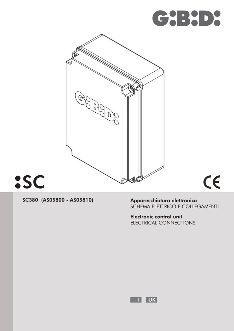
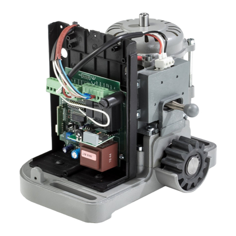
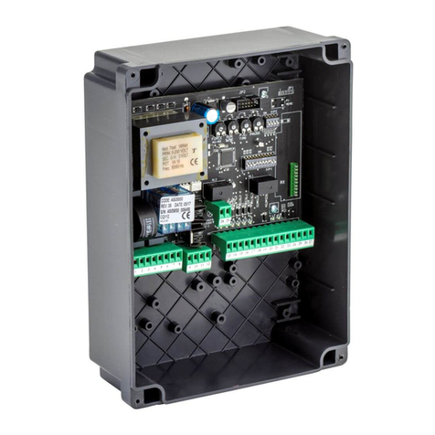
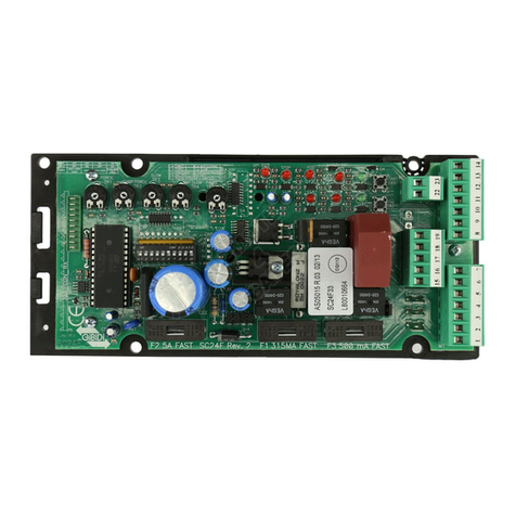
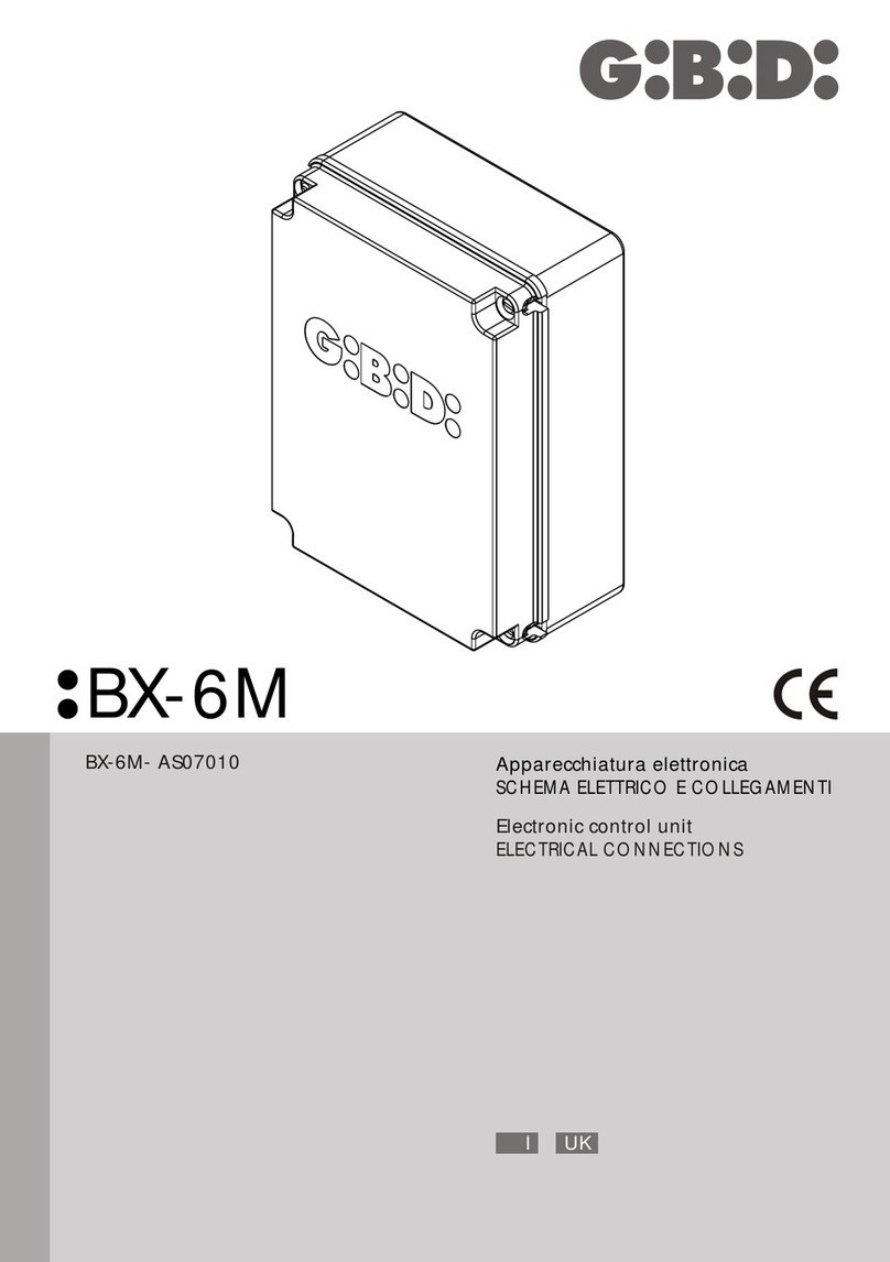
GiBiDi GECO LUX GECO60 Guide

GECO LUX
I UK F E
D P NL
GECO60 - (K020/08F1)
GECO80 - (K030/08F1)
Automazione a traino
ISTRUZIONI PER L’INSTALLAZIONE
Automated drive unit
INSTRUCTIONS FOR INSTALLATIONS

Prima di iniziare l'installazione, leggere integralmente e esattamente nell'ordine descritto, queste istruzioni di montaggio.
Accertarsi che la struttura della por ta sia in buono stato, ed adatta ad essere motorizzata.
Prima di ogni montaggio o intervento di manutenzione, assicurarsi di aver staccato l'alimentazione.
Verificare la tensione di alimentazione, la frequenza e la sicurezza.
Assicurarsi di operare lontano dalla pioggia, neve, umidità e materiali combustibili.
Assicurarsi di non operare sulla porta garage in movimento o sui componenti movimentati.
Assicurarsi che la porta in movimento, sia scorrevole e non sia soggetta a punti di attrito.
Assicurarsi che la porta sia ben bilanciata. Eventualmente, sarà necessario inter venire sui meccanismi di bilanciamento.
Assicurarsi che nei pressi della porta, non siano presenti bambini.
Far eseguire il montaggio e l'allacciamento elettrico a personale esperto e competente.
Utilizzare solamente accessori e ricambi originali Gi.Bi.Di.
Eseguire i fissaggi con la massima attenzione, in quanto sono in gioco forze elevate.
Predisporre vicino o in prossimità della posizione prevista dell'operatore, una presa alimentata a 230V, con dispositivo di disconnessione
dalla rete di alimentazione con distanza di aper tura tra i contatti di almeno 3 mm.
La non corretta installazione, fa decadere la garanzia.
Proteggere se necessario la zona pignone, rinviocatena e scorrimento.
Installare il gruppo in una zona non accessibile alle persone.
Se il cavo di alimentazione dovesse danneggiarsi, deve essere sostituito da un cavo o da un assieme speciale disponibile presso il
costruttore o il suo ser vizio di assistenza tecnica.
Accessori disponibili:
Istruzioni di installazione del Gruppo di Traino Versione da 600N.
Avvertenze Generali:
•
•
•
•
•
•
•
•
•
•
•
•
•
•
•
•
•
•
Porte sezionali ed a molle: Non è richiesto alcun accessorio.
Porte basculanti: è richiesto il braccio cur vo.
•
•
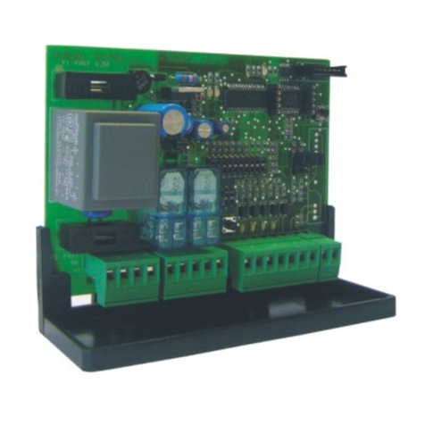
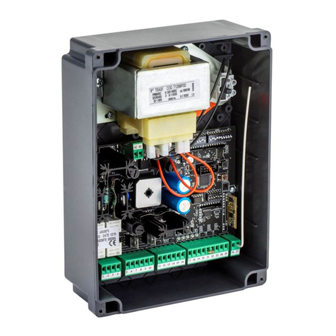
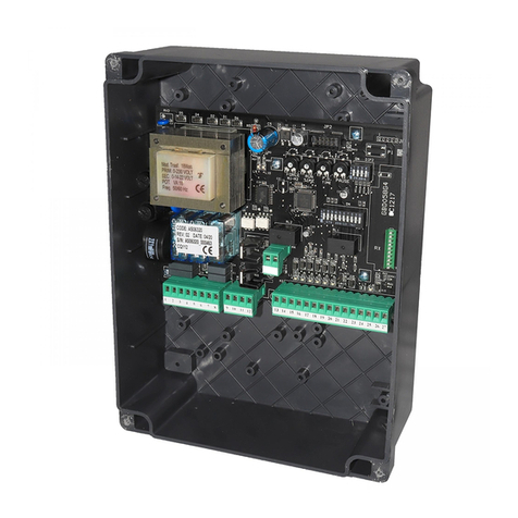
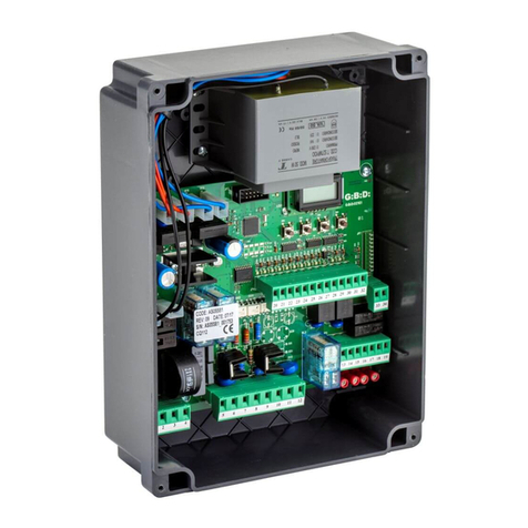
Caratteristiche della centrale elettronica AS02180 E AS02190:
Alimentazione 230Vac - 50/60Hz.
Protezione fusibile contro il cor tocircuito della linea di alimentazione generale ( F2 = F 1A ).
Protezione fusibile contro il cor tocircuito della linea di alimentazione a bassa tensione ( F1 = F 630mA ).
Possibilità di comando tramite un unico pulsante di Apre-Stop-Chiude oppure tramite radiocomando, solo per AS02180.
Dispositivo antischiacciamento a sensore amperometrico con soglia regolabile.
Predisposizione per il collegamento di fotodispositivi (24Vdc - 5W).
Uscita per il collegamento di un lampeggiante 24Vac 15W max.
Luce di cortesia a bordo operatore 230Vac 40W max. (E14) protetta con fusibile (F3 = 500mA).
La sostituzione della lampada di cortesia deve essere effettuata solo in assenza di alimentazione di rete (230 Vac).
Ingresso per il pulsante di STOP.
Led di alimentazione scheda - DL1.
Led della memorizzazione dei codici del radiocomando, solo per AS02180.
•
•
•
•
•
•
•
•
•
•
•
•
Accessori in confezione
Foto 01
Caratteristiche generali
Tensione di alimentazione 230 Vac 230 Vac
GECO 60 GECO 80
Frequenza tensione alimentazione 50 - 60 Hz 50 - 60 Hz
Potenza massima assorbita 250 W 250 W
Temperatura di utilizzo -10 / +55 -10 / +55
Spinta max. 600 N 800 N
Spinta nominale 200 N 200 N
Cicli ora 20 20
Attenzione: per l’installazione del braccio curvo su una porta basculante attenersi scrupolosamente al libretto di istruzioni in
dotazione all’accessorio.
Considerare che per il buon funzionamento di questo tipo di automazione è necessario che la porta basculante non sia completamente
aperta in modo da agevolare il più possibile la richiusura della stessa, così facendo è possibile evitare eventuali sovraccarichi al sistema.
Italiano
2
AUTOMATISMI PROFESSIONALI PER CANCELLI E GARAGE

Funzioni:
Rallentamento in aper tura (1 sec) e chiusura (4 sec).
Richiusura automatica selezionabile, con tempo di pausa regolabile 8-90 sec.
Funzione di prelampeggio in chiusura selezionabile.
Regolazione elettronica della forza di spinta.
•
•
•
•
Assemblaggio dell'operatore:
Unire i profili in acciaio con il giunto, assicurandosi che il giunto sia circa a metà.•
Foto 02
Foto 03
Foto 04
Attrezzatura necessaria per l'installazione.
Inserire il profilo in acciaio nel corpo motore sino in battuta.
Far passare la catena attorno al pignone.
•
•
Foto 06 Montare il blocco rinvio catena, inserendo la rondella, la molla, la rondella ed il dado.
Tendere leggiermente la catena.
•
•
Foto 07 Montare la staffa...
... utilizzando le viti, le rondelle ed i dadi.
•
•
Foto 10
Montare le staffe, utilizzando le viti e le rondelle.
Segnare la posizione dei fori delle staffe di fissaggio.
Forare e fissare il gruppo al soffitto mediante i tasselli forniti in confezione.
•
•
•
Foto 08 Fissare la staffa centralmente al telaio della porta o al muro utilizzando i tasselli forniti in confezione.
Distanza minima dal punto massimo di scorrimento dell’anta = 30mm.
•
Foto 05 Montare la staffa utilizzando le viti e le rondelle.•
Foto 13 Sbloccare la piastra del blocco finecorsa svitando l'apposita vite.
Trascinare la piastra lateralmente liberando le ghiere dei finecorsa.
•
•
Foto 15 Agire sulla ghiera inferiore per regolare il punto di fine corsa della chiusura.
A regolazione ultimata ripristinare la piastra blocca ghiere serrando la vite.
•
•
Foto 14 Agire sulla ghiera superiore per regolare il punto di fine corsa di apper tura.•
Foto 09
Piegare a misura le staffe nella parte superiore.
•
Fissare la staffa di traino al centro della porta, utilizzando le viti in confezione.
•
Foto 11
Collegare il braccio di traino alla staffa, evitando di bloccare il braccio stesso.
•
Foto 12
Per avere una migliore regolazione nella manovra di chiusura, può essere neccessario agire sull'asta di trascinamenento
della por ta.
•
Foto 16
Regolazione del finecorsa:
Importante: l'intervento del finecorsa, non blocca il movimento, ma determina l'inizio della fase di rallentamento del moviment o
della porta.
Attenzione: disporre il cavo di alimentazione in modo che non vada a contatto con parti in movimento (pignone - catena) rischia ndo
di danneggiarne l’isolamento.
Regolazione dei trimmer
Apparecchiature Gruppo di Traino - Vedere Dis. 17 per i collegamenti
Dis. 17
Foto 18 Tempo di pausa (RV1) :
•
•
•
Ruotato tutto in senso antiorario si disabilita la chiusura automatica (modo di funzionamneto passo-passo).
Aumentando il tempo si abilita la chiusura automatica da 8 Sec. fino ad un massimo di 90 secondi circa.
Durante le prove di installazione si consiglia di disabilitare la Chiusura automatica.
Impostazione di fabbrica a Zero. Tutto ruotato in senso antiorario.
Quando si alimenta la scheda un lampeggio della lampada di cortesia indica che la chiusura automatica è attiva.
Connettore per innesto radiocomando, solo per AS02190.
Scheda semaforo
Batteria tampone
•
•
•
Opzioni:
AUTOMATISMI PROFESSIONALI PER CANCELLI E GARAGE
Italiano
3

Italiano
4
AUTOMATISMI PROFESSIONALI PER CANCELLI E GARAGE
Foto 19
Funzioni:
•
•
•
In fase di aper tura blocca il movimento.
In fase di chiusura blocca il movimento e inverte per 1 secondo per liberare l'ostacolo.
N.B. Più la porta è bilanciata migliore è l'intervento del controllo.
Impostazione di fabbrica al 50%. Metà corsa.
Foto 20 Impostazione dei DIP
Regolazione coppia motore (RV2)
Ruotando il trimmer in senso antiorario si diminuisce la soglia di inter vento della coppia erogata dal motore, in senso
orario aumenta.
Attenzione: la modifica dei DIP viene acquisita togliendo l’alimentazione per 10 sec. (scheda OFF) e ripristinandola (scheda O N).
1Pos. OFF -
Pos. ON -
In fase di chiusura la fotocellula ferma il moto
In fase di chiusura la fotocellula inverte il moto (*)
DIP 1
3Pos. OFF -
Pos. ON -
Prelampeggio in fase di chiusura non attivo (*)
Prelampeggio in fase di chiusura attivo
DIP 3
4Pos. OFF -
Pos. ON -
Start da intervento fotocellula Disattivato (*)
Start da intervento fotocellula Attivato
(DEVE ESSERE ABILITATA LA RICHIUSURA AUTOMATICA E IL PRELAMPEGGIO IN CHIUSURA).
La funzione permette il comando della richiusura quando viene impagnata e poi liberata la fotocellula.
DIP 4
2Pos. - Tipo di funzionamento (VEDI FUNZIONAMENTO) DIP 2
5Pos. OFF -
Pos. ON -
Ingresso “photo” abilitato (morsetti M6 - M5)
Ingresso “photo” disabilitato (*)
6Non utilizzato
Funzionamento
(*) Impostazione di fabbrica
Con chiusura automatica inserita Senza chiusura automatica inserita
Per la chiusura automatica vedi Regolazione del tempo di pausa.
Con il DIP 2 in posizione OFF (*)
All’impulso di START l’operatore APRE, durante la fase di apertura
un successivo comando di START ferma il moto.
In qualsiasi punto la porta si trovi viene abilitata la CHIUSURA
AUTOMATICA ma viene ignorato un qualsiasi comando di START.
Scaduto il tempo di pausa l’operatore CHIUDE durante questa
fase un comando di START blocca o inverte il moto (vedi DIP1).
Con il DIP 2 in posizione OFF (*)
All’impulso di START l’operatore APRE, durante la fase di apertura
il comando di STRAT ferma il moto.
Un ulteriore comando di START CHIUDE la porta.
Con il DIP 2 in posizione ON
All’impulso di START l’operatore APRE la porta fino a finecorsa,
durante la fase di apertura un successivo comando di START
viene ignorato. A fine apertura viene abilitata la CHIUSURA
AUTOMATICA ma viene ignorato un qualsiasi comando di START.
Scaduto il tempo di pausa l’operatore CHIUDE durante questa
fase un comando di START blocca o inverte il moto (vedi DIP1).
Con il DIP 2 in posizione ON
All’impulso di START l’operatore APRE la porta fino a finecorsa,
durante la fase di apertura il comando di START viene ignorato.
Un ulteriore comando di START CHIUDE la porta.
Fissare il coperchio prima di alimentare l’operatore.•
Foto 21
PRIMA DI OGNI INTERVENTO SULL'IMPIANTO, ASSICURARSI CHE L'ALIMENTAZIONE NON SIA COLLEGATA.
Effettuare tutti i collegamenti ai pulsanti, collegare le fotocellule e portare il DIP 5 in OFF. Se vengono installate più copp ie di fotocellule,
i contatti devono essere posti in serie.
Se presente, collegare alla rispettiva uscita, il lampeggiatore.
Escludere per il momento la richiusura automatica, ruotando completamente il trimmer RV1 in senso antiorario.
Collegare alla rete (230Vac) il gruppo, tramite l'apposito cavo dotato di presa.
Alimentare l'impianto. A questo punto, si dovrebbe illuminare il led di presenza rete. Se ciò non succede, controllare i colleg amenti
alla linea 230Vac.
Ruotare il trimmer di regolazione della forza di spinta - RV2 - a circa il 50%.
Premere il pulsante di START. La por ta inizia la manovra di aper tura.
Premere il pulsante di STOP, al fine di verificarne il corretto funzionamento.
Rifare la manovra di apertura fino al raggiungimento del finecorsa di aper tura.
Controllare che in prossimità della posizione di apertura, l'operatore esegua il allentamento di 1 sec.
Nel caso in cui il rallentamento non venga eseguito, controllare il bilanciamento della porta, in posizione di aper tura.
Premere il pulsante di START. La por ta inizia la manovra di chiusura, fino al raggiungimento del finecorsa di chiusura.
Come nella manovra di aper tura, controllare che in prossimità della posizione di chiusura, l'operatore esegua il rallentamento di 4 sec.
Nel caso in cui il rallentamento non venga eseguito, controllare il bilanciamento della porta, in posizione di chiusura.
1
2
3
4
5
6
7
8
9
10

Verificare il corretto funzionamento dei dispositivi di sicurezza, tenendo presente che:14
Abilitare, se richiesto, le funzioni supplementari:15
Premendo il pulsante di STOP, l'operatore blocca ogni suo movimento, e resta in attesa di un comando di START.
L'intervento della fotocellula, durante la fase di aper tura, non provoca nessun intervento.
L'intervento della fotocellula, durante la fase di chiusura, può provocare due diversi compor tamenti dell'operatore:
•
•
•
Prelampeggio: provoca l'accensione del lampeggiante 3 sec prima dell'inizio del movimento della porta.; si abilita por tando il
DIP SWITCH (3), nella posizione ON.
•
L'intervento del sensore di massimo sforzo dell'operatore, durante la fase di apertura, provoca l'arresto immediato del movimen to.
L'intervento del sensore di massimo sforzo dell'operatore, durante la fase di chiusura, provoca la riaper tura della por ta per
circa 1 sec.
•
•
se il DIP SWITCH (1) è in posizione OFF, l'intervento della fotocellula blocca il movimento;
se il DIP SWITCH (1) è in posizione ON, l'inter vento della fotocellula, provoca l'immediata riapertura, fino al raggiungimento della
posizione di apertura.
-
-
Utilizzo della radio a bordo “per versione AS02180”
Programmazione codice dei radiocomandi
Foto 22 Premere il pulsante LEARN (S2) sull’apparecchiatura. La spia rossa (DL2) si accende per 5 sec.
Premere il pulsante del radiocomando prima dello scadere dei 5 sec. Un lampeggio della spia rossa indica che il codice
è stato memorizzato correttamente.
Per memorizzare ulteriori codici rifare la procedura appena elencata.
1
2
3
Premendo il tasto del radiocomando, precedentemente memorizzato, viene eseguito un comando di START.
Ad ogni pressione del tasto del radiocomando, la spia rossa indica, tramite un lampeggio, la corretta ricezione del segnale.
N.B. I codici memorizzabili sono al massimo 200.
L’apparecchiatura versione AS02190 è predisposta all’inserimento di una scheda radio ad innesto originale Gi.Bi.Di.
Per l’installazione attenersi all’istruzioni contenute nella confezione della radio stessa.
Cancellazione dei codici.
E' possibile applicare il KIT della batteria tampone per il funzionamento dell'operatore in assenza di tensione di rete 230 Vac .
Durante il funzionamneto esclusivamnete con batteria tampone l'operatore risulta essere leggermente più lento e la lampada di c ortesia
viene disabilitata. Tale batteria deve essere collegata ai morsetti "EMR” (polo positivo), e a "GND" (polo negativo).
Batteria tampone
Foto 24 Scheda semaforo
La scheda si fissa al gruppo mediante la vite del trasformatore e viene collegata mediante l'apposito cavo alla spina
che occorre saldare nella piazzola "SEMAPHORE".
La scheda è provvista di 2 uscite a contatto pulito (Relè 10 A 230 Vca Max.) con il seguente funzionamento:
• Mentre l'operatore è fermo in chiusura, entrambi i contatti sono aperti.
• Mentre l'operatore apre, uno dei contatti è chiuso e l'altro è aper to.
• Mentre la porta è aperta i contatti rimangono impostati come la fase di aper tura.
• Mentre chiude, il contatto chiuso durante l'apertura diventa aperto e l'altro si chiude.
•
Accessori
•
Attenzione Il collegamento di batterie direttamente ai morsetti causa guasti irreversibili all'apparecchiatura.
Usare solo il KIT batteria apposito GiBiDi per gruppo di traino.
Kit sblocco esterno
•
Braccio per porte a contrappesi
•
Regolare il tempo di richiusura automatica, se richiesto, ruotando in senso orario il trimmer (RV1).
Regolare la forza di spinta, tramite il trimmer (RV2), in maniera che con uno sforzo moderato dell'operatore, si abbia:
11
12
Tenere premuto il pulsante LEARN (S2) fino a che la spia rossa (DL2) dia una segnalazione di cancellazione avvenuta.1
Ripetere alcune volte la manovra di apertura, al fine di ottimizzare le regolazioni sopra descritte.13
L'arresto della por ta, nel caso sia in fase di apertura o in fase di frenatura;
La riaper tura parziale della porta, nel caso sia in fase di chiusura.
•
•
ATTENZIONE: Se premendo il pulsante LEARN (S2), la spia rossa esegue una serie di lampeggi, vuol dire la memoria dei codici è
piena, quindi non è possibile memorizzare ulteriori radiocomandi.
È possibile comunque eseguire la cancellazione di tutti i codici memorizzati.
ATTENZIONE: la cancellazione provoca la perdita di tutti i codici radio, si rende così necessario la riprogrammazione
dei radiocomandi.
Foto 23 Utilizzo della radio a innesto “per versione AS02190”
Assicurarsi che la fase di rallentamento abbia inizio almeno 150 mm prima della chiusura completa della porta. In caso contrari o,
regolare il finecorsa di chiusura, anticipandone l'intervento.
AUTOMATISMI PROFESSIONALI PER CANCELLI E GARAGE
Italiano
5

ANOMALIA POSSIBILE CAUSA / RIMEDIO
Led di alimentazione spento V erificare i fusibili e il cavo di alimentazione (1 A)
La scheda non apprende il codice TX Verifica dei codici massimi memorizzabili
Verifica della frequenza del radiocomando e ricevente
Lampeggio veloce del Led di programmazione (PROG.) Raggiungimento del numero max di codici
Memoria difettosa
L'operatore non apre Verificare il Finecorsa di apertura
Verificare i collegamenti fra scheda e Finecorsa
-
-
-
Lampada di cortesia non funzionante
Verificare la lampada ed il fusibile F3
Se l'operatore è alimentato dalle batterie
(assenza dell'alimentazione 230 Vca) la lampada di cor tesia
viene disabilitata.
-
-
L'operatore apre ma non richiude
Verificare degli ingressi delle sicurezze, Fotocellule, Stop ecc.
Verifica ingresso di Star t, deve essere aperto
Verifica Collegamento e finecorsa di aper tura
-
-
-
-
-
-
-
Non esegue il rallentamento Verificare il bilanciamento della porta
Verificare l'intervento dei finecorsa
-
-
L’ingresso fotocellula non interviene Verificare che il DIP 5 sia in OFF-
RISOLUZIONE DEI PROBLEMI
Prima di ogni montaggio o intervento di manutenzione, assicurarsi di aver staccato l'alimentazione.
Utilizzare solamente accessori e ricambi originali Gi.Bi.Di.
Italiano
6
AUTOMATISMI PROFESSIONALI PER CANCELLI E GARAGE

AUTOMATISMI PROFESSIONALI PER CANCELLI E GARAGE
Italiano
7
DICHIARAZIONE DI CONFORMITA’ CE
Gi.Bi.Di. Continental S.p.A.
Sede Legale
Sede Amministrativa - Ufficio Commerciale - Stabilimento:
Via Abetone Brennero, 177/B, 46025 Poggio Rusco (Mantova) ITALY
AUTOMAZIONE A TRAINO Mod. GECO 60/80
Il fabbricante:
Dichiara che il prodotto
sono conformi alle seguenti Direttive CEE:
Direttiva Bassa Tensione 73/23 e successive modifiche;
•
Direttiva Compatibilità Elettromagnetica 89/336 e successive modifiche;
e che sono state applicate le seguenti norme ar
Poggio Rusco, li 13/11/2013
monizzate:
EN 60335-1 • EN 50082-2 • EN 50081-1 • EN 300 220-3 • EN 301 489-1
EN 301 489-3 • EN 60950
•
Direttiva R&TTE 99/05;
•
Il Rappresentante Legale
Michele Prandi

English
8
PROFESSIONAL AUTOMATIC SYSTEM FOR GATES AND GARAGE DOORS
Before star ting installation, carefully read through these installation instructions exactly in the order described.
Ensure that the door structure is in a good state and suitable for motorization.
Before any installation or maintenance operation, check that the power supply has been disconnected.
Check the power supply voltage, the frequency and the safety switch.
Work away from rain, snow, humidity and combustible materials.
Do not work on a moving garage door or on moving components.
Check that the door moves smoothly and is not subject to points of friction.
Ensure that the door is well-balanced. If necessar y, adjust the balancing mechanisms.
Keep children away from the door.
Have the electrical connection and installation carried out by expert and skilled personnel.
Only use original Gi.Bi.Di spare par ts and accessories.
Be extremely careful when fixing the par ts, since high forces come into play.
Arrange a 230V outlet near or in proximity of the planned position of the operator with a mains power cut-off device with an op ening
distance between the contacts of at least 3 mm.
Improper installation will lead to forfeiture of the guarantee.
If necessar y, protect the pinion, chain transmission and sliding area.
Install the unit in an area not accessible to persons.
Should the power cable be damaged, it must be replaced with a cable or special assembly available at the manufacturer or
his technical ser vice.
Accessories available:
Installation instructions for the Drive Unit Version 600N
General warnings:
•
•
•
•
•
•
•
•
•
•
•
•
•
•
•
•
•
•
Sectional and spring-loaded doors: no accessories required.
Overhead doors: curved arm required.
•
•
Characteristics of the electronic control units AS01970 and AS01980:
Power supply 230VAC - 50/60Hz.
Fuse protection against shor t-circuits of the main power supply line (F2 = F 1A) .
Fuse protection against short-circuits of the low-voltage power supply line (F1 = F 630mA).
Possibility of control through one Open-Stop-close button or through radio control, only for AS02180.
Amperometric sensor anti-crushing device with adjustable threshold.
Provision for connection of photocells (24VDC - 5W).
Output for connection of a flashlight (24VAC 15W max.).
Courtesy light on the operator (230VAC 40W max. (E14) protected by fuse (F3 = 500mA).
The courtesy lamp may be replaced only when the power is off (230 VAC).
Input for STOP button.
Card power supply Led - DL1.
Radio-control code storage Led, only for AS02180.
•
•
•
•
•
•
•
•
•
•
•
•
Accessory packs
Photo 01
General characteristics
Power supply voltage 230 VAC 230 VAC
GECO 60 GECO 80
Power supply voltage frequency 50 - 60 Hz 50 - 60 Hz
Maximum power absorbed 250 W 250 W
Operating temperature -10 / +55 -10 / +55
Max. thr ust 600 N 800 N
Nominal thrust 200 N 200 N
Cycles/hour 20 20
Warning: For installation of the curved arm on the overhead door, strictly follow the instructions in the leaflet supplied with
the accessory.
Bear in mind that for good functioning of this type of automation, the overhead door must not be opened completely in order to
make reclosing as easy as possible and prevent any system overloads.

PROFESSIONAL AUTOMATIC SYSTEM FOR GATES AND GARAGE DOORS
English
9
Functions:
Deceleration during opening (1 sec) and closing (4 sec).
Selectable automatic reclosing with pause time adjustable between 8-90 sec.
Selectable pre-flashing function during closing.
Electronic control of thrust force.
•
•
•
•
Operator assembly:
Join the steel profiles to the coupling, ensuring that the coupling is about halfway.•
Photo 02
Photo 03
Photo 04
Equipment required for installation.
Fit the steel profile into place in the motor body untillstop is reached.
Wind the chain around the pinion.
•
•
Photo 06 Mount the chain transmission block, fitting the washer, spring, washer and nut.
Slightly tighten the chain.
•
•
Photo 07 Mount the bracket...
... using the screws, washers and nuts.
•
•
Photo 10
Mount the brackets, using the screws and washers.
Mark the position of the fixing bracket holes.
Drill the holes and fix the unit to the ceiling with the screw anchors provided in the accessory pack..
•
•
•
Photo 08 Fit the bracket in the centre of the door frame or to the wall using the screw anchors provided in the accessor y pack.
The minimum distance from the maximum sliding point of the door is 30 mm.
•
Photo 05 Mount the bracket using the screws and washers.•
Photo 13 Release the plate of the limit switch block by undoing the screw
Pull the plate sideways freeing the ring nuts of the limit switches.
•
•
Photo 15 Act on the lower ring nut to adjust the closing limit switch point.
When the adjustment has been made, refit the ring nut locking plate tightening the screw.
•
•
Photo 14 Act on the upper ring nut to adjust the opening limit switch point. •
Photo 09
Bend the brackets to size on the upper par t
•
Fit the draw bracket to the centre of the door using the screws provided in the accessory pack.
•
Photo 11
Connect the arm to the draw bracket, taking care not to lock the arm.
•
Photo 12
To obtain better adjustment of the closing manoeuvre it might be necessary to act on the drive rod of the door. •
Photo 16
Limit switch adjustment:
Important: The limit switch intervention does not lock the movement, but determines the start of the deceleration phase of the door
movement.
Caution: Arrange the power cable in such a way that it does not come into contact with the moving parts (pinion – chain) as th e
insulation could be damaged.
Trimmer adjustment
Drive Unit Equipment - See Drawing 17 for connections
Fig. 17
Photo 18 Pause time (RV1):
•
•
•
Completely turned anticlockwise, automatic closing is disabled (step-by-step operating mode).
Increasing the time, automatic closing is enabled from 8 sec. up to a maximum of about 90 sec.
It is recommended to disable automatic closing during the installation tests.
The factory setting is zero. All turned anticlockwise.
When the card is powered, the courtesy light will flash to indicate that automatic closing is active.
Connector to plug in radio control, only for AS02190.
Semaphore card.
Buffer batter y.
•
•
•
Options:

English
10
PROFESSIONAL AUTOMATIC SYSTEM FOR GATES AND GARAGE DOORS
Photo 19
Functions:
•
•
•
During the opening phase, it locks the movement.
During the closing phase it locks the movement and inverts for 1 second to free the obstacle.
N.B. The more balanced the door the better the intervention of the control.
The factory setting is at 50%, half-stroke.
Photo 20 DIP SWITCH Setting
Motor torque adjustment (RV2)
Turning the trimmer anticlockwise, the intervention threshold of the torque delivered by the motor is decreased, clockwise
increased.
Warning: DIP SWITCH modification is obtained by cutting the power for 10 sec. (card OFF) and then restoring it (card ON).
1Pos. OFF -
Pos. ON -
During the closing phase the photocell stops the motion
During the closing phase the photocell inverts the motion (*)
DIP 1
3Pos. OFF -
Pos. ON -
Pre-flashing during the closing phase inactive (*)
Pre-flashing during the closing phase active
DIP 3
4Pos. OFF -
Pos. ON -
Start from photocell intervention deactivated (*)
Start from photocell intervention activated
(AUTOMATIC CLOSING AND PRE-FLASHING DURING CLOSING MUST BE ENABLED).
The function allows controlling reclosing when the photocell is engaged and then released.
DIP 4
2Pos. - Type of operation (SEE OPERATION) DIP 2
Operation
(*) Factory setting
With automatic closing on Without automatic closing on
For automatic closing see Pause time adjustment.
With DIP2 in OFF position (*):
At the START pulse the operator OPENS; during the opening phase
a subsequent START command stops the motion.
AUTOMATIC CLOSING is enabled at whatever point the door is, but
any START command is ignored.
When the pause time has elapsed, the operator CLOSES; during
this phase a START command locks or inverts the motion (see DIP1).
With DIP2 in OFF position (*):
At the START pulse the operator OPENS; during the opening phase
a subsequent START command stops the motion.
A further START command CLOSES the door.
With DIP 2 in ON position:
At the START pulse the operator OPENS the door up to the limit
switch; during the opening phase a subsequent START command
is ignored. At the end of opening, AUTOMATIC CLOSING is ena-
bled, but any START command is ignored.
When the pause time has elapsed, the operator CLOSES; during
this phase a START command locks or inverts the motion (see DIP1).
With DIP2 in ON position:
At the START pulse the operator OPENS the door up to the limit
switch; during the opening phase the START command is ignored.
A fur ther START command CLOSES the door.
Fit the cover before powering the operator.•
Photo 21
BEFORE ANY OPERATION ON THE SYSTEM, ENSURE THAT THE POWER SUPPLY IS DISCONNECTED.
Make all the connections to the buttons and connect the photocells and take DIP 5 in OFF. If several pairs of photocells are in stalled,
the contacts must be placed in series.
If present, connect to flashlight to the respective output.
For the moment, cut out automatic reclosing, turning the trimmer RV1 completely anticlockwise.
Connect the unit to the mains (230 VAC) with the power cable provided.
Power the system. At this point, the power LED should come on. If this does not occur, check the connections to the 230 VAC lin e.
Turn the thrust force adjusting trimmer - RV2 - by about 50%.
Press the START button; the door star ts the opening manoeuvre.
Press the STOP button to check proper functioning.
Repeat the opening manoeuvre until reaching the opening limit switch.
Check that the operator decelerates for 1 sec. in proximity of the opening position.
If it does not decelerate, check balancing of the door in opening position.
Press the START button; the door star ts the closing manoeuvre until reaching the closing limit switch.
As with the opening manoeuvre, check that the operator decelerates for 4 sec. in proximity of the closing position.
If it does not decelerate, check balancing of the door in closing position.
1
2
3
4
5
6
7
8
9
10
5Pos. OFF -
Pos. ON -
Entrance “photo” activated (clamps M6 - M5)
Entrance “photo” not activated (*)
6Not used

PROFESSIONAL AUTOMATIC SYSTEM FOR GATES AND GARAGE DOORS
English
11
Ensure that the deceleration phase starts at least 150 mm before complete closure of the door. If not, adjust the closing limit
switch, anticipating the intervention.
Check proper functioning of the safety devices, bearing in mind that: 14
Enable, if required, the supplementar y functions:15
When the STOP button is pressed, the operator locks all its movements and waits for a START command.
The photocell inter vention during the opening phase does not activate any operation.
The photocell inter vention during the closing phase, may cause two dif ferent behaviours of the operator:
•
•
•
Pre-flashing: causes the flashlight to come on 3 sec. before star ting the door movement; it is enabled by setting the DIP SWITC H (3)
to the ON position.
•
The intervention of the maximum thrust sensor of the operator during the opening phase causes immediate stopping of the movemen t.
The intervention of the maximum thrust sensor of the operator during the closing phase causes reopening of the door for
about 1 sec.
•
•
if DIP SWITCH (1) is in the OFF position, the photocell inter vention locks the movement;
if DIP SWITCH (1) is in the ON position, the photocell intervention causes immediate reopening until reaching the opening
position.
-
-
Use of built-in radio “for version AS02180”
Radio control code programming
Photo 22 Press the LEARN (S2) button on the control unit. The red light - DL2 - comes on for 5 sec.
Press the radio control button before the 5 sec. elapse. When the red light flashes it means that the code has been
stored correctly.
To store fur ther codes repeat the above described procedure.
1
2
3
When the previously stored radio control button is pressed, a START command is executed.
Each time the radio control button is pressed, the red light indicates, by flashing, that the signal has been received correctl y.
N.B. A maximum of 200 codes can be stored.
Provision has been made on the control unit version AS02190 to plug in the original Gi.Bi.Di. plug-in radio card.
For installation follow the instructions that come with the radio.
Deleting the codes
The buffer battery kit can be used when the 230 VAC mains power fails to ensure continued functioning of the operator.
During operation with only the buffer battery, the operator is slightly slower and the cour tesy lamp is disabled.
The battery must be connected to the "EMRG" (positive pole) terminal and to the “GND” (negative pole) terminal.
Buffer battery
Photo 24 Semaphore card
The card is fixed to the unit by means of the transformer screw and is connected with a special cable to the outlet which
you should weld in the stopping place "SEMAPHORE".
The card has 2 clean-contact outputs (relay 10A 230 VAC max.) with the following operation:
• While the operator is off during closing, both contacts are open.
• While the operator opens, one of the contacts is closed and the other open.
• While the door is open, the contacts remain set as in the opening phase.
• While it closes, the contact closed during opening opens and the other one closes.
•
Accessories
•
Warning: Connecting batteries directly to the terminals causes irreversible damage to the control unit.
Use only the special Gi.Bi.Di battery kit for the drive unit.
External unlocking kit
•
Arm for counterweight doors
•
Adjust the automatic reclosing time, if required, by turning the trimmer RV1 clockwise.
Adjust the thrust force with the trimmer RV2 in such a way that with a moderate force of the operator you obtain the following:
11
12
Hold the LEARN (S2) button pressed down until the red light - DL2 - emits a signal that deletion has been completed.1
Repeat the opening manoeuvre several times in order to optimise the above described adjustments. 13
Stopping of the door if in the opening or braking phase;
Partial reopening of the door if in the closing phase.
•
•
WARNING: If the red light flashes fast when the LEARN (S2) button is pressed, it means that the code memory is full and further
radio controls cannot be stored.
All the stored codes can however be deleted.
WARNING: The deletion will cause the loss of all the radio codes and the radio controls will have to be reprogrammed.
Photo 23 Use of the plug-in radio “for version AS02190”

English
12
PROFESSIONAL AUTOMATIC SYSTEM FOR GATES AND GARAGE DOORS
FAULT POSSIBLE CAUSE / REMEDY
Power LED off Check the fuses and the power cable (1 A)
The card does not learn the TX code Check the maximum number of storable codes
Check the frequency of the radio control and the receiver
Fast flashing of the programming LED (PROG.) Max. number of codes reached
Memory fault
The operator does not open Check the opening limit switch
Check the connection between card and limit switch
-
-
-
Courtesy lamp not working
Check the lamp and the fuse F3
If the operator is batter y-powered
(230VAC power supply failure)
the cour tesy lamp is disabled.
-
-
The operator opens but does not reclose
Check the inputs of the safety switches, photocells, Stop, etc.
Check the Start input, it must be open
Check connection and opening limit switch
-
-
-
-
-
-
-
The operator does not decelerate Check door balancing
Check limit switch intervention
-
-
TROUBLESHOOTING
Before any installation or maintenance operation, ensure that the power supply has been disconnected.
Use only original Gi.Bi.Di. spare parts and accessories.
Photocell entrance does not intervene Verify that DIP 5 is in OFF-

PROFESSIONAL AUTOMATIC SYSTEM FOR GATES AND GARAGE DOORS
English
13
CONFORMITY DECLARATION CE
Gi.Bi.Di. Continental S.p.A.
Legal Office
Administrative Office-Commercial Dpt.-Factory:
Via Abetone Brennero, 177/B, 46025 Poggio Rusco (Mantova) ITALY
AUTOMATED DRIVE UNIT Mod. GECO 60/80
The manufacturer:
declares that the product:
Are in conformity with the following CEE Directives:
Low Voltage Directive 73/23 and following modifications;
Electromagnetical Compatibility Directive 89/336 and following modifications;
And that the following harmonized Norms have been applied:
Poggio Rusco, 13/11/2013
EN 60335-1 • EN 50082-2 • EN 50081-1 • EN 300 220-3 • EN 301 489-1
EN 301 489-3 • EN 60950
R&TTE Directive 99/05;
•
•
•
The legal Representative
Michele Prandi

Français
14
AUTOMATISMES PROFESSIONNELS POUR GRILLES ET PORTES DE GARAGE
Avant de commencer l'installation, lire entièrement et parfaitement dans l'ordre décrit les consignes de montage ci-dessous:
Vérifier que la structure de la porte est en bon état et prévue pour être motorisée.
Avant tout montage ou toute inter vention d'entretien, vérifier que le courant a été coupé.
Vérifier la tension d'alimentation, la fréquence et la sécurité. .
S'assurer de travailler loin de la pluie, de la neige, de l'humidité et de matériaux combustibles.
S'assurer de ne pas agir sur la porte du garage en mouvement ou sur les composants actionnés.
S'assurer que la por te en mouvement est coulissante et n'est pas sujette à des points de frottement.
S'assurer que la por te est bien équilibrée. Le cas échéant, intervenir sur les mécanismes d'équilibrage.
S'assurer qu'il n'y a pas d'enfants autour de la por te.
Faire effectuer le montage et le branchement électrique par un personnel qualifié et compétent.
N'utiliser que des accessoires et des pièces détachées Gi.Bi.Di.
Effectuer les fixations avec la plus grande attention, car il y a d'impor tantes forces en jeu.
Prévoir à côté ou à proximité de l'emplacement de l'opérateur, une prise alimentée à 230V avec dispositif de déconnexion du sec teur
d'alimentation ayant une distance d'ouver ture entre les contacts d'au moins 3 mm.
Une mauvaise installation annule automatiquement la garantie.
Si nécessaire, protéger la zone du pignon, du renvoi de la chaîne et du coulissement.
Installer le groupe dans un endroit inaccessible aux personnes.
Si le câble d'alimentation devait s'abîmer, il faut le remplacer par un câble ou par un ensemble spécial disponible chez le con structeur
ou auprès de son Service d'assistance technique.
Accessoires disponibles:
Instructions pour l'installation du Groupe de Traction Version de 600N.
Consignes générales:
•
•
•
•
•
•
•
•
•
•
•
•
•
•
•
•
•
•
Portes à sections et à ressor ts: aucun accessoire ne s'impose.
Portes basculantes: Un bras arrondi est exigé.
•
•
Caractéristiques de platine électronique AS01970 et AS01980:
Alimentation 230Vca - 50/60Hz.
Protection fusible contre le court-circuit de la ligne d'alimentation générale ( F2 = F 1A ).
Protection fusible contre le court-circuit de la ligne d'alimentation à basse tension ( F1 = F 630mA ).
Possibilité de commande au moyen d'un seul bouton de Ouvre-Stop-Ferme ou bien à l'aide d'une radiocommande, uniquement pour AS0 2180.
Dispositif contre l'écrasement à capteur ampèremétrique, à sensibilité réglable.
Adaptation pour le raccordement de photodispositifs (24Vcc - 5W).
Sortie pour le raccordement du clignotant 24Vca 15W maximum.
Eclairage de courtoisie sur l'opérateur 230Vca 40W maximum (E14) protegée par fusible (F3 = 500mA).
La lampe de l'éclairage de courtoisie ne doit être changée qu'avec l'alimentation de secteur coupée (230 Vca).
Entrée pour le bouton de STOP.
Led indiquant l'alimentation de la car te - DL1.
Led indiquant la mémorisation des codes du radiocommande, uniquement pour AS02180.
•
•
•
•
•
•
•
•
•
•
•
•
Accessoires en confection
Photo 01
Caractéristiques générales
Tension d'alimentation 230 Vac 230 Vac
GECO 60 GECO 80
Fréquence tension d'alimentation 50 - 60 Hz 50 - 60 Hz
Puissance maximum absorbée 250 W 250 W
Température de service -10 / +55 -10 / +55
Poussée maximum 600 N 800 N
Poussée nominale 200 N 200 N
Cycles heure 20 20
Attention: pour l'installation du bras arrondi sur une porte basculante suivre scrupuleusement le livret d'instructions dont
l'accessoire est équipé. Tenir en ligne de compte que pour le bon fonctionnement de ce type d'automatisation la porte basculant e
ne doit pas être tout à fait ouverte de manière à faciliter le plus possible le réenclenchement de celle-ci, ce faisant il est possible
d'éviter d'éventuelles surcharges au système.

AUTOMATISMES PROFESSIONNELS POUR GRILLES ET PORTES DE GARAGE
Français
15
Fonctions:
Ralentissement en ouverture (1 sec) et en fermeture (4 sec).
Refermeture automatique sélectionnable, avec temps de pause réglable 8-90 sec.
Fonction de préclignotement en fermeture sélectionnable.
Réglage électronique de la force de poussée.
•
•
•
•
Assemblage de l'opérateur:
Unir les profils en acier avec le joint, en s'assurant que ce dernier se trouve environ à la moitié.•
Photo 02
Photo 03
Photo 04
Equipement nécessaire pour l'installation.
Introduire le profil en acier dans le corps moteur jusqu'à la butée.
Faire passer la chaîne autour du pignon.
•
•
Photo 06 Monter le bloc renvoi de chaîne, introduire la rondelle, le ressor t, la rondelle et l'écrou.
Serrer de manière à ce que la chaîne soit légèrement tendue.
•
•
Photo 07 Monter l'étrier...
...en utilisant les vis, les rondelles et les écrous.
•
•
Photo 10
Monter les étriers, en utilisant les vis et les rondelles.
Marquer la position des trous des étriers de fixation.
Percer et fixer le groupe au plafond à l'aide des chevilles fournies dans la confection.
•
•
•
Photo 08 Fixer l'étrier au centre du bâti de la por te ou du mur en utilisant les chevilles fournies dans la confection.
Distance minimum du point maximum de coulissement de la porte = 30 mm.
•
Photo 05 Monter l'étrier en utilisant les vis et les rondelles.•
Photo 13 Débloquer la plaque de blocage de la fin de course en dévissant la vis appropriée.
Traîner la plaque latéralement en dégageant les frettes des fins de course.
•
•
Photo 15 Agir sur la frette inférieure pour régler le point de fin de course de la fermeture.
Le réglage terminé, rétablir la plaque de blocage des frettes, en serrant la vis.
•
•
Photo 14 Agir sur la frette supérieure pour régler le point de fin de course d'ouverture.•
Photo 09
Plier comme il se doit les étriers dans la partie supérieure.
•
Fixer l'étrier de traction au centre de la porte, en utilisant les vis fournies dans la confection.
•
Photo 11
Relier le bras de traction à l'étrier, en évitant de bloquer ce dernier.
•
Photo 12
Pour optimiser le réglage, pendant la manœuvre de fermeture, agir sur la tige d'entraînement de la por te.•
Photo 16
Réglage de la fin de course:
Important: l'enclenchement de la fin de course, ne bloque pas le mouvement, mais détermine le début de la phase de ralentisseme nt
du mouvement de la porte.
Attention: disposer le câble d'alimentation en sorte qu'il n'aille pas au contact de pièces en mouvement (pignon - chaîne), ce qui
risquerait d'en abîmer l'isolation.
Réglage des potentiomètres
Appareillages groupe de traction - Voir Des. 17 pour les enclenchements
Des. 17
Photo 18 Temps de pause (RV1):
•
•
•
En le tournant entièrement dans le sens inverse aux aiguilles d'une montre, c'est la fermeture automatique qui est
déconnectée (mode de fonctionnement de pas-à-pas).
En augmentant le temps on autorise la fermeture automatique de 8 sec. jusqu'à un maximum d'environ 90 secondes.
Pendant les essais d'installation il est conseillé de désactiver la fermeture automatique.
Paramétrage en usine à 0. Entièrement tourné dans le sens inverse aux aiguilles d'une montre.
Lorsque la carte est alimentée, un clignotement de l'éclairage de courtoisie indique que la fermeture automatique est activée.
Connecteur pour radiocommande à enclenchement, uniquement pour AS02190.
Carte feu
Alimentation de secours
•
•
•
Options:

Français
16
AUTOMATISMES PROFESSIONNELS POUR GRILLES ET PORTES DE GARAGE
Photo 19
Fonctions:
•
•
•
Pendant la phase d'ouverture c'est le mouvement qui est bloqué.
Pendant la phase de fermeture c'est le mouvement qui est bloqué et l'inversion se fait pendant 1 seconde pour libérer l'obstacl e.
N.B. Plus la porte est équilibrée plus l'intervention du contrôle est optimisée.
Paramétrage en usine à 50%. A mi-course.
Photo 20 Paramétrage des DIP
Réglage du couple moteur (RV2)
En tournant le potentiomètre dans le sens inverse aux aiguilles d'une montre, on diminue le seuil d'enclenchement du
couple fourni par le moteur et dans le sens des aiguilles d'une montre on l'augmente.
Attention: La modification des DIP est acquise en coupant l'alimentation (carte OFF) pendant 10 sec., puis en remettant le cour ant (carte ON).
1Pos. OFF -
Pos. ON -
Dans la phase de fermeture la cellule photoélectrique arrête le mouvement
Dans la phase de fermeture la cellule photoélectrique inverse le mouvement (*)
DIP 1
3Pos. OFF -
Pos. ON -
Préclignotement en phase de fermeture non actif (*)
Préclignotement en phase de fermeture actif
DIP 3
4Pos. OFF -
Pos. ON -
Start d'inter vention de la cellule photoélectrique désactivé (*)
Start d'inter vention de la cellule photoélectrique activé
(LE REFERMETURE AUTOMATIQUE ET LE PRECLIGNOTEMENT EN FERMETURE DOIVENT ETRE AUTORISES EN FERMETURE).
La fonction autorise la commande de la refermeture lorsque la cellule photoélectrique est interceptée, puis libérée.
DIP 4
2Pos. - Type de fonctionnement (VOIR FONCTIONNEMENT) DIP 2
Fonctionnement
(*)Paramétrage en usine
Avec fermeture automatique activée Sans fermeture automatique activée
Pour la fermeture automatique voir Réglage du temps de pause.
Avec le DIP 2 sur la position OFF (*).
A l'impulsion de START l’opérateur OUVRE, au cours de la phase
d'ouverture, une commande successive de START arrête le mou-
vement. Dans quelque point que ce soit où la porte se situe, la
FERMETURE AUTOMATIQUE sera activée, en ignorant n'importe
quelle commande de START. Le temps de pause écoulé, l'opéra-
teur FERME, au cours de cette phase une commande de START,
bloque ou inverse le mouvement (voir DIP1).
Avec le DIP 2 sur la position OFF(*).
A l'impulsion de START l’opérateur OUVRE, au cours de la phase
d'ouverture la commande de START arrête le mouvement.
Une commande ultérieure de START ferme la porte.
Avec le DIP 2 sur la position ON.
A l'impulsion de START l’opérateur OUVRE la porte jusqu'à la fin
de course, pendant la phase d'ouverture une commande succes-
sive de START est ignorée. A la fin de l'ouverture est activée la
FERMETURE AUTOMATIQUE et n'importe quelle commande de
START est ignorée. Le temps de pause écoulé, l'opérateur FERME,
au cours de cette phase une commande de START bloque ou
inverse le mouvement (voir DIP1).
Avec le DIP 2 sur la position ON.
A l'impulsion de START l’opérateur OUVRE la por te jusqu'à la fin
de course, pendant la phase d'ouver ture la commande de START
est ignorée.
Une commande ultérieure de START FERME la porte.
Fixer le couvercle avant d'alimenter l'opérateur.•
Photo 21
AVANT TOUTE INTERVENTION SUR L'INSTALLATION, S'ASSURER QUE L'ALIMENTATION N'EST PAS CONNECTEE.
Effectuer tous les raccordements aux boutons, relier les cellules photoélectriques et por ter le DIP 5 en OFF. Si plusieurs séries de
cellules photoélectriques sont installées, les contacts doivent être placés en série.
Connecter le clignotant à la sor tie respective, s'il est installé.
Exclure pour le moment la réfermeture automatique, en tournant complètement le potentiomètre RV1 dans le sens inverse aux aigui lles d'une montre.
Connecter au secteur (230Vca) le groupe, à l'aide du câble approprié doté de prise.
Alimenter l'installation. Dans ces conditions, le témoin lumineux signalant le courant sur le secteur doit s'allumer. Si ce n' est pas
le cas, contrôler les raccordements à la ligne 230Vca.
Tourner le potentiomètre de réglage de la force de poussée - RV2 - à environ 50%.
Appuyer sur le bouton de START. La por te commence la manœuvre d'ouverture.
Appuyer sur le bouton STOP, afin d'en contrôler le bon fonctionnement.
Répéter la manœuvre d'ouverture pour arriver à la fin de course d'ouverture.
Contrôler qu'à proximité de la position d'ouver ture, l'opérateur effectue le ralentissement de 1 sec.
Si le ralentissement ne s'effectue pas, contrôler l'équilibrage de la porte, en position d'ouver ture.
Appuyer sur le bouton de START. La por te commence la manœuvre de fermeture, pour arriver à la fin de course de fermeture.
Comme pour la manœuvre d'ouverture, contrôler qu'à proximité de la position de fermeture, l'opérateur effectue le ralentissemen t de 4 sec.
Si le ralentissement ne s'effectue pas, contrôler l'équilibrage de la por te, en position de fermeture.
1
2
3
4
5
6
7
8
9
10
5Pos. OFF -
Pos. ON -
Entrée “photo” habilitée (bornes M6 - M5)
Entrée “photo” dishabilitée (*)
6Pas utilisé

AUTOMATISMES PROFESSIONNELS POUR GRILLES ET PORTES DE GARAGE
Français
17
S'assurer que la phase de ralentissement commence bien au moins 150 mm avant la fermeture complète de la porte.
Si ce n'est pas le cas, régler la fin de course de fermeture, en en anticipant l'enclenchement.
Vérifier le bon fonctionnement des dispositifs de sécurité, en sachant que: 14
Valider, si demandé, les fonctions supplémentaires:15
En appuyant sur le bouton de STOP, l'opérateur bloque tout mouvement et attend une commande de START.
L'intervention de la cellule photoélectrique, pendant la phase d'ouverture, ne provoque aucun enclenchement.
L'intervention de la cellule photoélectrique, pendant la phase de fermeture, peut entraîner deux comportements différents de l' opérateur:
•
•
•
Préclignotement: entraîne l'allumage du clignotant pendant 3 sec. avant le début du mouvement de la por te: pour l'activer, régl er le
DIP SWITCH (3) sur la position ON.
•
L'intervention du capteur d'ef fort maximum de l'opérateur, pendant la phase d'ouver ture, entraîne l'arrêt immédiat du mouvement .
L'intervention du capteur d'ef fort maximum de l'opérateur, pendant la phase de fermeture, entraîne la réouver ture de la por te p en-
dant environ 1 sec.
•
•
si le DIP SWITCH (1) est sur la position OFF, l'intervention de la cellule photoélectrique bloque le mouvement;
si le DIP SWITCH (1) est sur la position ON, l'intervention de la cellule photoélectrique entraîne immédiatement la réouverture ,
pour revenir en position d'ouver ture.
-
-
Utilisation de la radiocommande à bord “pour version AS02180”
Programmation du code des radiocommandes
Photo 22 Appuyer sur le bouton LEARN (S2) sur l'appareillage. Le voyant lumineux rouge - DL2 - s'allume pendant 5 sec.
Appuyer sur le bouton de la radiocommande avant que s'écoulent les 5 secondes. Un clignotement du voyant rouge
indique que le code a été parfaitement mémorisé.
Pour mémoriser d'autres codes, refaire la procédure décrite ci-dessus.
1
2
3
En appuyant sur la touche de la radiocommande, précédemment mémorisée, c'est la commande de START qui est exécutée.
A chaque pression de la touche de la radiocommande, le voyant rouge indique, par un clignotement, la par faite réception du sign al.
N.B. Les codes pouvant être mémorisés sont au nombre maximum de 200.
L’appareillage version AS02190 est prévu pour l'insertion d'une car te de radiocommande à embrayage original Gi.Bi.Di.
Quant à l'installation, suivre les consignes figurant dans la boîte de la radiocommande en question.
Suppression des codes.
Il est possible d'appliquer le KIT de l'alimentation de secours pour le fonctionnement de l'opérateur sans tension sur le secte ur de 230 Vca.
Au cours du fonctionnement exclusivement à l'aide d'une alimentation de secours, l'opérateur s'avère légèrement plus lent et
l'éclairage de cour toisie est désactivé. Cette alimentation doit être connectée aux bornes "EMR" (pôle positif), et "GND" (néga tif).
Alimentation de secours
Photo 24 Carte feu
La carte se fixe au groupe à l'aide de la vis du transformateur et est reliée grâce au câble, prévu à cet effet, à la fiche
qu’il faut souder dans la placette "SEMAPHORE".
La car te est équipée de 2 sorties à contact propre (relais 10 A 230 V ca maxi) ayant le fonctionnement suivant:
• Lorsque l'opérateur est arrêté en fermeture, les deux contacts sont ouverts.
• Lorsque l'opérateur ouvre, l'un des contacts est fermé et l'autre est ouver t.
• Lorsque la por te est ouver te, les contacts restent programmés de même que la phase d'ouverture.
• Lorsqu'il ferme, le contact fermé pendant l'ouverture s'ouvre et l'autre se ferme.
•
Accessoires
•
Attention: la connexion de batteries directement aux bornes est la cause de dommages irréversibles à l'appareillage.
N'utiliser que le KIT batterie GiBiDi prévu à cet effet pour groupe de traction.
Kit déblocage extérieur
•
Bras pour portes à contrepoids
•
Régler le temps de réfermeture automatique, si demandé, en tournant dans le sens des aiguilles d'une montre le potentiomètre RV 1.
Régler la force de poussée, à l'aide du potentiomètre RV2, de manière à ce qu'avec un effort modéré de l'opérateur, se produit:
11
12
Tenir la touche LEARN (S2) enfoncée jusqu'à ce que le témoin lumineux rouge - DL2 - donne un signal, qui confirme que l'élimina tion de
tous les codes mémorisés a été effectuée.
1
Répéter plusieurs fois la manœuvre d'ouverture, afin d'optimiser les réglages indiqués ci-dessus.13
L'arrêt de la porte, si elle est en phase d'ouverture ou en phase de freinage;
La réouver ture partielle de la porte, si elle est en phase de fermeture.
•
•
ATTENTION: Si on appuie sur le bouton LEARN (S2), le voyant rouge exécute toute une série de clignotements, ce qui veut dire qu e
la mémoire des codes est pleine, c'est pourquoi il est impossible de mémoriser d'autres radiocommandes.
De toute façon il est possible d'exécuter la suppression de tous les codes mémorisés.
ATTENTION: la suppression cause la perte de tous les codes de la radiocommande, ce qui impose la reprogrammation des
radiocommandes.
Photo 23 Utilisation de la radiocommande à embrayage “pour version AS02190”

ANOMALIE CAUSE POSSIBLE/SOLUTION
Témoin lumineux d'alimentation éteint Vé rifier les fusibles et le câble d'alimentation (1 A)
La car te n'apprend pas le code TX Contrôle des codes maximums mémorisables
Contrôle de la fréquence de la radiocommande et du récepteur.
Clignotement rapide du témoin lumineux de programmation (PROG.) Le nombre maximum de codes a été atteint
Mémoire défectueuse
L'opérateur n'ouvre pas. Vérifier la fin de course d'ouverture.
Contrôler les raccordements entre la car te et la fin de course
-
-
-
Eclairage de courtoisie ne fonctionnant pas
Vérifier la lampe et le fusible F3
Si l'opérateur est alimenté par des batteries
(absence de l'alimentation 230 Vca)
l'éclairage de courtoisie est désactivé.
-
-
L'opérateur ouvre mais ne referme pas.
Vérifier les entrées des dispositifs de sécurité,
cellules photoélectriques, Stop etc.
Contrôler l'entrée de Star t, elle doit être ouverte.
Contrôler le raccordement et la fin de course d'ouverture
-
-
-
-
-
-
-
Ne ralentit pas. Contrôler l'équilibrage de la porte.
Contrôler l'enclenchement des fins de course.
-
-
RESOLUTION DES PROBLEMES
Avant tout montage ou toute intervention d'entretien, s'assurer que l'alimentation a été coupée.
N'utiliser que des accessoires et des pièces détachées d'origine Gi.Bi.Di.
Français
18
AUTOMATISMES PROFESSIONNELS POUR GRILLES ET PORTES DE GARAGE
L’entrée photocellule n’intervient pas Vérifier que le DIP 5 soit en OFF-

AUTOMATISMES PROFESSIONNELS POUR GRILLES ET PORTES DE GARAGE
Français
19
DÉCLARATION DE CONFORMITÉ CE
Gi.Bi.Di. Continental S.p.A.
Siège Légale
Siège Administrative - Bureau Commercial - Usine:
Via Abetone Brennero, 177/B, 46025 Poggio Rusco (Mantova) ITALY
AUTOMATISME A TRACTION Mod. GECO 60/80
Le fabricant:
déclare que le produit:
sont conformes aux suivant Directives CEE:
Directive Basse Tension 73/23 et successives modifications;
Directive Compatibilité Electromagnétique 89/336 et successives modifications;
et qu’on a appliqué les suivantes normes harmonisées:
Poggio Rusco, 13/11/2013
EN 60335-1 • EN 50082-2 • EN 50081-1 • EN 300 220-3 • EN 301 489-1
EN 301 489-3 • EN 60950
Directive R&TTE 99/05;
•
•
•
Le Représentant Légal
Michele Prandi

Deutsch
20
PROFESSIONELLE TOR- UND GARAGENÖFFNER
Vor Beginn der Installation, diese Montageanleitung vollkommen und aufmerksam durchlesen.
Sich vergewissern, daß sich die Torstruktur in gutem Zustand befindet und zur Motorisierung geeignet ist.
Sich vor der Montage oder Wartungsarbeiten vergewissern, daß die Speisung abgetrennt wurde.
Die Speisespannung, Frequenz und Sicherheit überprüfen.
Sich darüber vergewissern, daß nicht in der Reichweite von Regen, Schnee, Feuchtigkeit und brennbaren Materialien gearbeitet wi rd.
Sicherstellen, daß nicht am gerade laufenden Garagentor oder beweglichen Bauteilen gearbeitet wird.
Sich vergewissern, daß das bewegte Tor gleitet und keinen Reibungsstellen unterliegt.
Sicherstellen, daß das Tor gut ausgeglichen ist. Gegebenenfalls die Ausgleichsmechanismen verstellen.
Sich vergewissern, daß sich keine Kinder in Nähe des Tores aufhalten.
Die Montage und den Elektroanschluß von erfahrenem Fachpersonal durchführen lassen.
Nur Originalzubehör und -ersatzteile von Gi.Bi.Di. verwenden.
Die Befestigungen mit größter Sorgfalt vornehmen, weil sehr große Kräfte auftreten.
In Nähe der für den Antrieb vorgesehenen Stelle eine mit 230 V gespeiste Steckdose mit Vorrichtung zur Trennung vom
Versorgungsnetz mit einer Kontaktöffnung von mindestens 3 mm anbringen.
Die unsachgemäße Installation macht die Garantie nichtig.
Falls nötig den Bereich Ritzel, Kettenvorgelege und Gleitung schützen.
Das Aggregat in einem für Personen unzugänglichen Bereich installieren.
Im Falle der Beschädigung eines Speisekabels, muß dieses durch ein Kabel oder ein beim Hersteller oder dem technischen
Kundenservice erhältliches Spezialset ersetzt werden.
Erhältliche Zubehörteile:
Montageanleitung für das Antriebsaggregat Version 600N.
Allgemeine Warnungen:
•
•
•
•
•
•
•
•
•
•
•
•
•
•
•
•
•
•
Mehrtafelige und Feder tore: Es ist kein Zubehör nötig.
Kipptore: Es ist ein gekrümmter Arm nötig.
•
•
Merkmale des elektronischen Steuergeräts AS01970 und AS01980:
Speisung 230VWs - 50/60Hz.
Schmelzsicherung gegen den Kurzschluß der allgemeinen Zuleitung ( F2 = F 1A ).
Schmelzsicherung gegen den Kurzschluß der Niederspannungs-Zuleitung ( F1 = F 630mA).
Möglichkeit zur Steuerung durch einen einzigen Knopf Öf fnen-Stop-Schließen oder durch Funksteuerung, nur für AS02180.
Quetschschutzvorrichtung mit Stromsensor und verstellbarer Schwelle.
Vorbereitung für den Anschluß von Lichtschranken (24VGs - 5W).
Ausgang zum Anschluß eines Blinklichts max. 24VWs 15W.
Zusätzliches Licht am Antrieb max. 230VWs 40W (E14) mit Sicherung geschützt (F3 = 500mA).
Die Birne der zusätzlichen Beleuchtung darf nur ausgetauscht werden, wenn keine Netzspannung (230 VWs) vorhanden ist.
Eingang für den STOP Knopf.
Led Platinenspeisung - DL1.
Led der Speicherung der Funksteuerungscodes, nur für AS02180.
•
•
•
•
•
•
•
•
•
•
•
•
Mitgeliefertes Zubehör
Foto 01
Allgemeine Merkmale
Speisespannung 230 VWs 230 VWs
GECO 60 GECO 80
Frequenz Speisespannung 50 - 60 Hz 50 - 60 Hz
Max. Leistungsaufnahme 250 W 250 W
Betriebstemperatur -10 / +55 -10 / +55
Max. Schubkraft 600 N 800 N
Nennschubkraft 200 N 200 N
Zyklen/Stunde 20 20
Achtung: Bei der Anbringung des gekrümmten Armes an einem Kipptor sich genau an die mit dem Zubehörteil gelieferte
Gebrauchsanleitung halten.
Bitte berücksichtigen, daß es für den guten Betrieb eines derartigen Antriebs nötig ist, daß das Kipptor nicht ganz geöffnet is t,
um dessen Wiederschließung zu erleichtern; auf diese Weise lassen sich Überlastungen des Systems vermeiden.
This manual suits for next models
3
Table of contents
Other GiBiDi Control Unit manuals
Popular Control Unit manuals by other brands

Polycom
Polycom RMX 1500 Administrator's guide

Siemens
Siemens FCM2041-U3 installation instructions

Intermatic
Intermatic P1353ME instruction manual

fesing
fesing SSIF2P15S48100C Applications manual

Roger Technology
Roger Technology B70/2B Instruction and warnings for the installer

Feasycom
Feasycom FSC-DB006 user guide