Benewake CE30-D User manual

CE30-D Solid-State Array LiDAR
Operation Manual
Page 1

Benewake(Beijing)Co., Ltd
CE30-D Product Manual - V04
Page 2
Product
Product model: CE30-D
Product name: Solid-state LiDAR
Manufacturer
Company name: Benewake(Beijing) Co., Ltd.
Address: NO.28 Xinxi Road, Haidian District, Beijing, China
Copyright
The Copyright of this document is protected. All the rights involved herein belong to
Benewake (Beijing) Co., Ltd. Any copy activity of this document, no matter in whole or in part,
should be in conformity of the Copyright Law. The actives of modification, omission or
translation of this document are not allowed unless a written permission from Benewake (Beijing)
Co., Ltd.
All rights reserved © Benewake (Beijing) Co., Ltd.

Benewake(Beijing)Co., Ltd
CE30-D Product Manual - V04
Page 3
Table of Contents
1. CE30-D introduction..........................................................................................................................4
2. Operation of Display Program........................................................................................................... 4
2.1 Connection....................................................................................................................................5
2.2 Display program window............................................................................................................. 6
3. Coordinate transformation................................................................................................................. 7
4. Indicator Instruction........................................................................................................................... 7
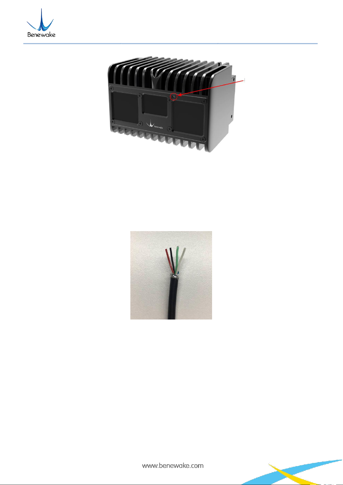
5. Line sequence descriptions................................................................................................................ 8
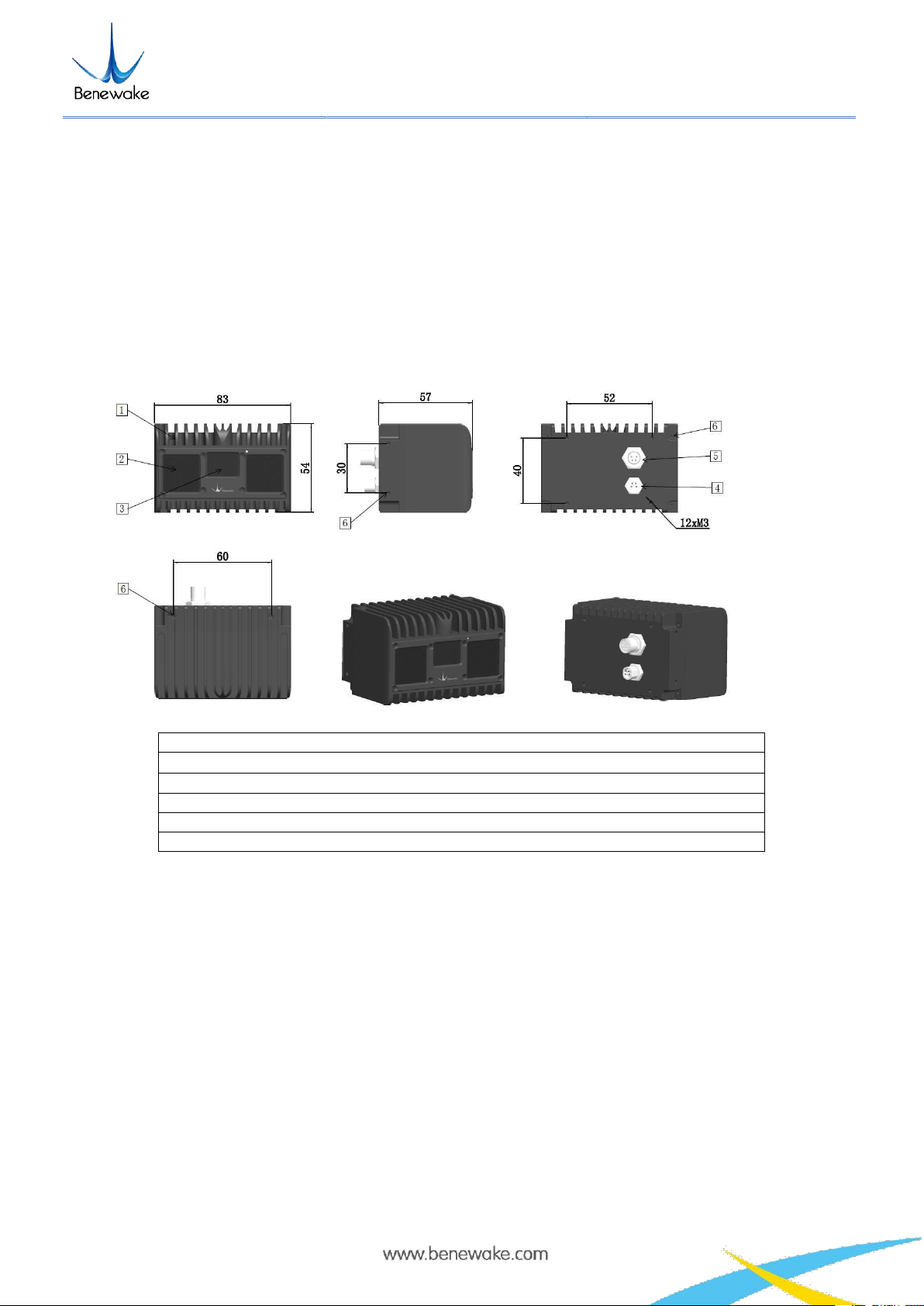
6. Installation diagram............................................................................................................................8
7. Test Instruction and Description........................................................................................................ 9
7.1 Detecting Range Description........................................................................................................9
7.1.1 Blind Zone............................................................................................................................. 9
7.1.2 Detecting Range.....................................................................................................................9
7.2 Vertical Angle Resolution.......................................................................................................... 10
7.3 Interference of Ambient light..................................................................................................... 11
7.4 Influence of Temperature........................................................................................................... 11
8. Influence Factors of Measurement...................................................................................................12
8.1 Multi Optical Path...................................................................................................................... 12
8.2 Stray Light.................................................................................................................................. 12
8.3 Multi Distance Objects............................................................................................................... 13
9. Frequently Asked Questions............................................................................................................ 13

Benewake(Beijing)Co., Ltd
CE30-D Product Manual - V04
Page 4
1. CE30-D introduction
CE30-D is a solid-state array LiDAR developed based on the TOF theory. Compared with single-
channel scanning LiDARs, there is no any mechanical rotating component, so it can run steadily
and reliably for a long time, able to get a wider range of vertical detection.
At the top, bottom, left, right and back, CE30-D has mounting location holes provided, through which it can
be fixed with peripheral devices reliably. See Figure 1 for the positions and spacing of the mounting holes
subject to the size of M3.
1. Enclosure
2. Emitting panel (working area , cannot be covered)
3. Reception panel (working area , cannot be covered)
4. Power
5. Ethernet interface (M8 aerial plug)
6. Equipment installation hole (M3)
Figure 1 DELIADAR CE30-D outer dimensions
2. Operation of Display Program
CE30-D has provided a complete SDK based on Linux and Windows systems for customers’ fast
development and use. Please log on to our wibeside to get the SDK source code and the corresponding
documentation.
http://en.benewake.com/download.html
This display program is used to process and display the output data of CE30-D LiDAR under the Windows
operating system. Before using this display program, please confirm that the local folder of the display
program contains complete documents necessary for operation:

Benewake(Beijing)Co., Ltd
CE30-D Product Manual - V04
Page 5
Figure 2 Display program and documents necessary for its operation
2.1 Connection
Figure 3 CE30-D aerial plug wiring instructions
a. Use the two aerial plug cables attached in the package (including one power supply plug cable and one
network port plug cable) to connect the LiDAR with the aerial plug cables as illustrated in Figure 3;
connect the power interface to the adapter DC 12V (≥3A), DC 5.5*2.5mm; connect the aerial plug
network port (RJ45) to the computer.
b. Set the Ethernet IP address and subnet mask in the directory “Control panel\Network and
Internet\Network Connections” as shown in Figure 5.
Figure 4 Network Settings
c. Open the CMD command interface in the Windows running window; enter and execute the command to
check whether the data connection is available:
ping 192.168.1.80 -t
Name
Ethernet
Power

Benewake(Beijing)Co., Ltd
CE30-D Product Manual - V04
Page 6
If it prompts as shown in Figure 6, it indicates that the LiDAR is working normally with the data connection
available. If no, it indicates that the data link suffers from ping failures. Please check as follows:
a) Check whether the indicators light up on the front panel of the LiDAR and whether the red lamp keeps
normally on and flashing after startup;
b) Check whether the power supply is available and whether the voltage is 12V with the rated current ≥ 3A;
c) Check whether the computer network port is normally connected and whether the local Ethernet is
identified;
d) Disconnect the power supply and wait for 5 seconds before reconnecting it.
Figure 5 Data connection check
2.2 Display program window
Double click the program ce30_pointcloud_viewer.exe to open the display program and the prompt and
point cloud image windows will appear as illustrated in Figure 6 for LiDAR version and operation shortcuts.
The prompt window is used to display the LiDAR connection, shortcut prompts and other running
information.
The point cloud image window displays the point cloud images in the LiDAR field of view calculated based
on the depth map and projection relation. In this window, hold down the left mouse button and move the
mouse to change the direction for viewing the point cloud images; use the mouse wheel and you can zoom
in/out the point cloud image; hold down the mouse wheel and move the mouse to move the point cloud
image horizontally.

Benewake(Beijing)Co., Ltd
CE30-D Product Manual - V04
Page 7
Figure 6 Information prompt window
Figure 7 Point cloud image window
When the program runs, it will display the following window for shortcut keys.
a)
CTRL+1
Switch to Aerial View (default);
b)
CTRL+2
Switch to Vertical View;
c)
CTRL+T
Switch to Normal/Stretched;
d)
CTRL+L
Save the current frame data and press it again to stop.
Note: The shortcut keys are effective only in the point cloud window. Click the point cloud information
window to activate it on the Windows interface.
3. Coordinate transformation
The CE30-D outputs distance and angle by polar coordinates. In order to facilitate the reconstruction and
application of 3D point cloud image, they can be transformed into rectangular coordinate system by the
following formula. X, Y and Z represent the coordinates of rectangular coordinate system, respectively.
X = Dist ×sin (90 − V) ×cos H − 30
Y = Dist ×sin (90 − V) ×sin (H − 30)
Z = Dist × sin (90 − V)
Declaration:
Dist: the distance output by photoreceptor cell;
V: Vertical, which is the vertical angle of photoreceptor cell, has the angle range from -1.9°to +1.9°
H: Horizontal, which is the horizontal angle of photoreceptor cell, has the angle range from 0° to 60°
4. Indicator Instruction

Benewake(Beijing)Co., Ltd
CE30-D Product Manual - V04
Page 8
Figure 8 Indicator position
1) Blue normally on: In the “Ready” state, it can be connected to work.
2) Blue flashing: It is working.
3) Red flashing: The relevant run files are missing.
4) Red normally on: Fatal error (abnormal signal, abnormal interface communication, abnormal I2C, etc.)
5. Line sequence descriptions
Figure 9 Line sequence at the power supply port: red - power positive, black - power negative
Note:
1. The current should be more than 3A for the power adapter;
2. When the LiDAR is powered on, it may be rarely possible to suffer from longer startup delay; if it doesn't
start in 2 minutes, cut off the power and restart as recommended;
3. To have it stop working, first disconnect its power supply and then disconnect other connecting lines.
6. Installation diagram
Indicator

Benewake(Beijing)Co., Ltd
CE30-D Product Manual - V04
Page 9
Figure 10: Recommendation for LiDAR installation. The LiDAR front interface must extrude from (at least be aligned
to) the front plane of the installation platform; otherwise, the data accuracy will be lower due to interference.
7. Test Instruction and Description
7.1 Detecting Range Description
7.1.1 Blind Zone
When detecting objects with high reflectivity, a blind zone as shown in Figure 11 would appear. This
is caused by the overexposure when objects’ reflected light is excessive. LiDAR will filter the data
from this overexposure zone. When the detected object’s reflectivity is lower, the blind zone can
become smaller. The blind zone is 20 cm long when detect objects with 10% reflectivity
.
Figure 11 Blind zone distribution (test with 90% reflectivity objects)
7.1.2 Detecting Range
The maximum detectable range is different in different area of field of view. The detectable area of a
90% reflectivity object is shown in Figure 12.
Front interface
Installation platform

Benewake(Beijing)Co., Ltd
CE30-D Product Manual - V04
Page
10
Figure 12 CE30-D's detecting area
7.2 Vertical Angle Resolution
CE30-D has 20 lines in vertical direction, and the vertical angle resolution is 0.2 degree, so that CE30-D has
more precise resolution capacity. The detection angle in vertical direction is presented in Table 1.
Table 1 Detecting angle in vertical direction
Vertical
Line
Vertical Angle
(°)
1
1.9
2
1.7
3
1.5
4
1.3
5
1.1
6
0.9
7
0.7
8
0.5
9
0.3
10
0.1
11
-0.1
12
-0.3
13
-0.5
14
-0.7
15
-0.9
16
-1.1
17
-1.3
18
-1.5
19
-1.7
20
-1.9

Benewake(Beijing)Co., Ltd
CE30-D Product Manual - V04
Page
11
7.3 Interference of Ambient light
LiDAR can work at ambient light with 60klux intensity, but the error increases compared with indoor
situation. The error in different testing conditions is presented in Figure 13.
Figure 13 Comparison of indoor and outdoor Error
Note:
1. The figure only show the error within 17m. The evaluated sample is 4x4 pixels in the central of field.
The performance of different machines differ from each other.
2. The outdoor and indoor accuracy within 7m are at the same level. The detecting performance with
different reflectivities are within expectation. The outdoor accuracy at long range is slightly poor, as
shown in the above figure.
3. The standard deviation of a whole frame of pixels are within 10cm. The difference range can be up to
40cm.
4. The abnormal performance outdoors: when the sunlight emmits straight into the optical window of the
LiDAR, 15% of the measuring data is unrealiable.
7.4 Influence of Temperature
The LiDAR is tested in different ambient temperature to obtain the detecting repeatability when temperature
changed. The Figure 14 presents an example of data from a single LiDAR. The evaluated
example is 4x4 pixels in the central of field.

Benewake(Beijing)Co., Ltd
CE30-D Product Manual - V04
Page
12
Figure 14 Dist Error varies with external Temp at different distance
8. Influence Factors of Measurement
8.1 Multi Optical Path
Based on ToF LiDAR principle, if there are multiple echo regions as shown in the figure below at the
working height of the radar, the multi-path phenomenon will be triggered: the LiDAR receives the light
returned by the path 1 and the path 2 at the same time, which may result in a larger measurement value.
Figure 15 Multi optical path phenomenon
8.2 Stray Light

Benewake(Beijing)Co., Ltd
CE30-D Product Manual - V04
Page
13
As shown below, when solid-state ToF LiDAR is working, in addition to the light reflected by the object 1,
the light scattered by object 2 and object 3 that close to the LiDAR will enter the lens. Such stray light can
lead to a deviation of the object 1’s ranging.
Figure 16 illustration of stray light
8.3 Multi Distance Objects
The light radiated by the LiDAR is reflected by the object onto the sensor of the LiDAR. If some pixels
receive signals from both front and rear obstacles at the same time, the output distance of this pixel may be
the value between the two obstacles. The degree of deviation is related to the distance between the two
obstacles and the material.
Figure 17 Multi distance objects
9. Frequently Asked Questions
Q1: After LiDAR is powered on, the display program of Windows crashes when opening, and present the
interface as shown in the Figure 18
A1: Please make sure the indicator of radar is on. It will take about 30 seconds to start after radar is
powered on, and the indicator is flashing.

Benewake(Beijing)Co., Ltd
CE30-D Product Manual - V04
Page
14
Q2: From the manual, the power supply is DC 12V ±0.5V (≥3A),and power consumption is 8w. So
how much is the working current?
A2: The normal working current is lower than 0.65A when radar working normally. There will be relatively
high pulse current when radar is detecting distance, the peak of pulse current is lower than 3A.
Other manuals for CE30-D
1
Table of contents
Other Benewake Accessories manuals

Benewake
Benewake TF03 User manual

Benewake
Benewake CE30-C User manual

Benewake
Benewake TF02-Pro-W-485 User manual

Benewake
Benewake TF03 User manual

Benewake
Benewake TF350 User manual

Benewake
Benewake TF350-RS-485 User manual

Benewake
Benewake TF02-Pro-W-485 User manual

Benewake
Benewake TF350 User manual

Benewake
Benewake TF02-i User manual

Benewake
Benewake TF03 User manual