Beninca LADY 4 User manual

CL854313111/2016 rev 0
LADY 4
UNIONE NAZIONALE COSTRUTTORI
AUTOMATISMI PER CANCELLI, PORTE
SERRANDE ED AFFINI
EN


3
C
B
A
222
40
324
1008
MAX. 4,0m
MIN. 2,0m
MAX. 4,2m
MIN. 2,2m
1
3
320
135
222
200
2
Dimensioni d’ingombro
Overall dimensions
Platzbedarf
Dimensions d’encombrement
Dimensiones totales
Wymiary gabarytowe
Rosetta Ø13x24 UNI 6592.
Washer Ø13x24 UNI 6592.
Unterlegscheibe Ø13x24 UNI 6592.
Rondelle Ø13x24 UNI 6592.
Arandela Ø13x24 UNI 6592.
Podkładka Ø 13x24 UNI 6592
Dado M12 UNI 5588.
Nut M12 UNI 5588.
Mutter M12 UNI 5588.
Ecrou M12 UNI 5588.
Tuerca M12 UNI 5588.
Nakrętka M12 UNI 5588
Mettere in piano la piastra tramite livella
Lay the plate flat using a spirit level
Die Platte mit Hilfe einer Wasserwaa-
ge gerade ausrichten
Mettre la plaque de niveau avec un
niveau à bulle
Nivelar horizontalmente la placa
con el nivel
Wypoziomować płytę za pomocą
poziomnicy.
Livella.
Spirit level
Wasserwaage
Niveau
Nivel
Poziomnica
Foro per passaggio cavi
Hole for passing cables
Loch für Kabeldurchgang
Trou pour passage des câbles
Orificio para el paso de cables
Otwór do przepuszczania kabli.
Piastra di fondazione
Foundation plate
Fundamentplatte
Plaque de fondation
Placa de cimentación
Płyta montażowa.
Staffa a cementare
Cementing-in bracket
Bügel zum Einbetonieren
Patte à sceller
Estribo a cimentar.
Kotwa do zabetonowania.
Accessorio VE.PS
Accessory VE.PS
Zubehör VE.PS
Accessoire VE.PS
Accesorio VE.PS
Akcesoriów VE.PS
VE.PS Kit
VE.PS Kit
VE.PS Kit
VE.PS Kit
VE.PS Kit
VE.PS Kit

4
4
5
Piastra.
Plate.
Platte.
Platine
Placa.
Płyta
Asta LADY.A.
Bar LADY.A.
Stange LADY.A.
Lisse LADY.A.
Asta LADY.A.
Ramię LADY.A
Supporto.
Support.
Auflage.
Support.
Soporte.
Wspornik
Colonna
Column
Säule
Fût
Columna
Kolumna
Vite M14x30 UNI 5933.
Screw M14x30 UNI 5933.
Schraube M14x30 UNI 5933.
Vis M14x30 UNI 5933.
Tornillo M14x30 UNI 5933.
Sruba M14x30 UNI 5933
Vite M8x16 UNI 5931.
Screw M8x16 UNI 5931.
Schraube M8x16 UNI 5931.
Vis M8x16 UNI 5931.
Tornillo M8x16 UNI 5931.
Sruba M8x16 UNI 5931
Rosetta Ø8.4x17 UNI 6592.
Washer Ø8.4x17 UNI 6592.
Unterlegscheibe Ø8.4x17 UNI 6592.
Rondelle Ø8.4x17 UNI 6592.
Arandela Ø8.4x17 UNI 6592.
Podkładka Ø 8.4x17 UNI 6592
V ring (V 60A)
Barriera destra
Right barrier
Schranke rechts
Barrière droite
Barrera derecha
Bariera prawa
Barriera sinistra
Left barrier
Schrank links
Barrière gauche
Barrera izquierda
Bariera lewa
F2F1
L L
F2F1

5
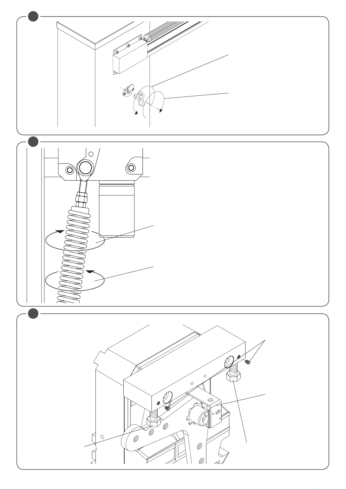
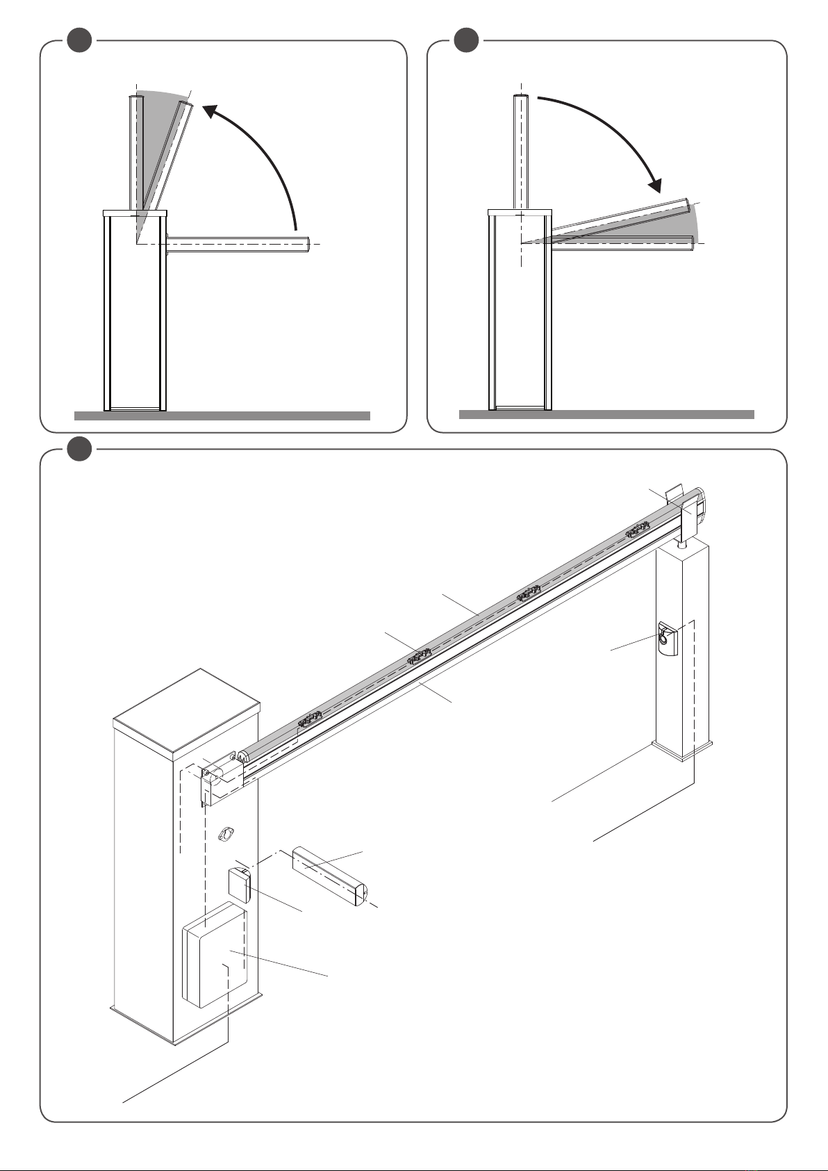
Fermo meccanico apertura
Mechanical stop on opening
Mechanische Feststellvorrichtung Öffnen
Butée mécanique en ouverture
Tope mecánico de apertura
Blokada mechaniczna otwarciu
6
7
8
Sblocco di emergenza
Emergency release
Notentriegelung
Déblocage de secours
Desbloqueo de emergencia
Rozsprzęglanie awaryjne
Ripristino automatismo
Reset automation
Reset des Automatismus
Réinitialisation automatisme
Reactivación del automatismo
Przywrócenie działania automatyzmu
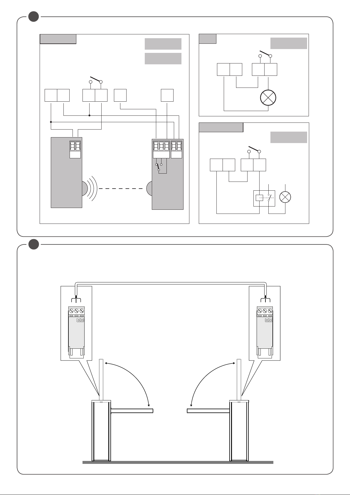
Con motoriduttore sbloccato:
With geared motor released:
Bei entriegeltem Getriebemotor:
Avec l’opérateur débloqué :
Con motorreductor desbloqueado:
Z motoreduktorem odblokowanym:
Se l'asta tende a chiudere, aumentare la tensione della molla (distendere la molla con rotazione oraria)
If the bar tends to close, increase the spring tension (extend the spring by turning clockwise)
Wenn die Stange dazu neigt, zu schließen, die Spannung der Feder erhöhen (durch Drehen im Uhrzeigersinn
entspannen)
Si la lisse a tendance à s’abaisser, augmenter la tension du ressort (détendre le ressort en tournant
dans le sens des aiguilles d’une montre)
Si el asta tiende a cerrarse, aumentar la tensión del muelle (descomprimir el muelle girándolo a la derecha)
Jeśli ramię szlabanu ma tendencję do zamykania się, należy zwiększyć napięcie sprężyny (rozkuźnić
sprężynę przez pokręcanie zgodnie z ruchem wskazówek zegara)
Se l'asta tende ad aprire, diminuire la tensione della molla (comprimere la molla con rotazione antioraria)
If the bar tends to open, decrease the spring tension (compress the spring by turning anti-clockwise)
Wenn die Stange dazu neigt, zu öffnen, die Spannung der Feder vermindern (durch Drehen im
Gegenuhrzeigersinn komprimieren)
Si la lisse a tendance à se lever, diminuer la tension du ressort (comprimer le ressort en tournant
dans le sens inverse des aiguilles d’une montre)
Si el asta tiende a abrirse, disminuir la tensión del muelle (comprimir el muelle girándolo hacia la izquierda)
Jeśli ramię szlabanu ma tendencję do otwierania się, należy zmniejszyć napięcie sprężyny (scisnąć
sprężynę poprzez pokręcanie w kierunku odwrotnym do ruchu wskazówek zegara)
Fermo meccanico chiusura
Mechanical stop on closing
Mechanische Feststellvorrichtung Schließen
Butée mécanique fermeture
Tope mecánico de cierre
Blokada mechaniczna zamknięcia
Grani di bloccaggio
Blocking dowels
Arretierstifte
Goujons de blocage
Tornillos sin cabeza de bloqueo
Kołki blokujące
Encoder assoluto
Absolute encoder
Absolut-Encoder
Encodeur absolu
Codificador absoluta
Enkodera absolutnego

6
2
3
3x1
2x1
2x1
4
6
7
1
2x1
4x1
2x1.5
230 V
5
8
Mod. VE.AF / VE.AFS (Optional)
11
Slow-down
Close (SLDC)
Slow-down
Open (SLDo)
O
C
O
C
9 10

7
RADIO
BLINKAUX2
J1
COM
SWO
SWC
STOP
ABS. ENCODER
PHOT
OPEN
SHLD
ANT
CLOSE
P. P.
U5
F1
MOTAUX - 24V +
BLINKAUX2
COM
SWO
SWC
STOP
PHOT
OPEN
SHLD
ANT
CLOSE
P. P.
MOTAUX
- +- +
ANT
M
LAMP.
24Vdc
24Vdc
500 mA
CP.EVA2
BAR
LIGHT
24Vdc
L
LED 1
LED 2
F1
N
+-
SA.24V
100÷250 Vac
+ -
-+
2xDA.BT2
(Optional)
SIS
(Optional)
Advantouch
- 24V +
+ BAT
- BAT
+
-
M3
M1
M2
MENC
12

8
Schema menu di programmazione - Menu programming layout
Diagramm Programmiermenü - Menu de programmation
Menú de la carta de programación - Układ menu programowania
v1.05
8888 Inst Boom
POS
3-5 ok
7-8
0---
---0
ok
ok
ok
PRG
PRG
PRG
PRG
PRG
PRG
PRG
PRG
PRG
PRG
PRG
PRG
PRG
PRG
PRG
PRG
tca
fsts
sldo
sldc
tsmo
pmo
pmc
pso
psc
seav
sear
20
99
50
50
20
tsmc
20
20
20
20
0
0
TLS 60
saso 0
sasc 0
0
AUX1
20
LOG
RADI
TCA
tca
IBL
IBCA
SCL
PP
PRE
htr
ltca
tst1
tstm
cvar
lbar
aopf
rem
pp
2ch
n TX
clr
rtr
OPen
Clse
TCA
LOG nman
PAR
Power ON
Display OFF
Firmware Ver. (3s)
Diagnostic

9
on PRG
OFF PRG
OFF PRG
OFF PRG
OFF PRG
OFF PRG
OFF PRG
off PRG
off PRG
OFF PRG
ON PRG
off PRG
off PRG
off PRG
PUSH OK
PUSH OK
0012
PUSH OK
rtr PRG OK
PUSH OK
PUSH OK
0000 conf OK
res PRG
OFF PRG
0012 3456
Nman
MACI
RES
CODE
Inst id
9000 9C5a
BUS
AUTO OK
0
OFF
PUSH
ID
Loc
RE-ENTER
CODE
Display OFF
2 Cycle
OPEN/CLOSE
PRG
PRG
Legenda
Premere il tasto (-) / Press key (-) / Die Taste (-) drücken
Appuyez sur la touche (-) / Presionar la tecla (-) / Wcisnąć przycisk (-)
Premere il tasto (+) / Press key (+) / Die Taste (+) drücken
Appuyez sur la touche (+) / Presionar la tecla (+) / Wcisnąć przycisk (+)
Premere il tasto (PG) / Press key (PG) / Die Taste (PG) drücken
Appuyez sur la touche (PG) / Presionar la tecla (PG )/ Wcisnąć przycisk (PG)
Premere simultaneamente (+) e (-) / Press simultaneously keys (+) and (-)
Gleichzeitig (+) und (-) drücken / Presser simultanément (+) et (-)
Presionar simultáneamente (+) y (-) / Naciskać jednocześnie (+) i (-)
Selezionare il valore desiderato con i pulsanti (+) e (-)
Increase/decrease the value with keys (+) and (-)
Mit den Tasten (+) und (-) kann man eingerichtete Werte ändern
Régler la valeur désirée avec les touches (+) et (-)
Establecer con las teclas (+) y (-) el valor deseado
Nastawia przyciskami (+) i (-) obraną wartoś
Selezionare il pulsante del trasmettitore da associare alla funzione
Press the transmitter key, which is to be assigned to function
Taste des Sendegeräts drücken, dem diese Funktion zugeteilt werden soll.
Appuyer sur la touche du transmetteur qu’e l’on désire affecter à cette fonction.
Presionar la tecla del transmisor que se desea asignar a esta función.
Wcisnąć przycisk nadajnika, który zamierza się skojarzyć z tą funkcją.

10
SIS
GND B A GND B A
SIS
24V ac 24V ac
COM
NC NO
RXTX
-
24Vdc
COM
AUX1
PHOT
+
-
24Vdc
AUX1
+
AUX1:0004
tst1:on
SCA
PHOTOTEST
AUX1:0000
AUX1:0003
-
24Vdc
AUX1
+
SERVICE LIGHT
L N
230Vac
LAMP
24Vac
LAMP
Relè
24Vdc
MASTER
Menu BUS
ID=0
SLAVE
Menu BUS
ID=1
3x0,5mm
13
14

20
QUICK PROGRAMMING
- Press the <PG> button, the display goes to the "INST" menu
- Enter the INST menu
- Verify that the parameter BOOM is correct: 3-5 for all LADY models (factory settings).
- Set the barrier position by means of the menu POS, by default the barrier is set as RIGHT BARRIER
- Enter the menu AUTO, confirm with <PG> and wait until the barrier has carried out the autoset of the parameters
- By means of the menus PAR and LOG, select the parameters and the logic functions wanted according to the type of installation
in object
IMPORTANT:After every change of the parameters FSTS. SLDO, SLDC, TSMO, TSMC, the barrier executes an opening maneuver
followed by a closing one in order to acquire the new values of current and torque, on the screen will appear the message <PRG>
ENG WARNING
GENERAL INFORMATIONS
The product shall not be used for purposes or in ways other than those for which the product is intended for and as described in this manual.
Incorrect uses can damage the product and cause injuries and damages.
The company shall not be deemed responsible for the non-compliance with a good manufacture technique of gates as well as for any de-
formation, which might occur during use. Keep this manual for further use.
INSTALLER GUIDE
This manual has been especially written to be use by qualified fitters. Installation must be carried out by qualified personnel (professional
installer, according to EN 12635), in compliance with Good Practice and current code. Make sure that the structure of the gate is suitable
for automation. The installer must supply all information on the automatic, manual and emergency operation of the automatic system and
supply the end user with instructions for use.
GENERAL WARNINGS
Packaging must be kept out of reach of children, as it can be hazardous. For disposal, packaging must be divided the various types of
waste (e.g. carton board, polystyrene) in compliance with regulations in force. Do not allow children to play with the fixed control devices of
the product. Keep the remote controls out of reach of children. This product is not to be used by persons (including children) with reduced
physical, sensory or mental capacity, or who are unfamiliar with such equipment, unless under the supervision of or following training by
persons responsible for their safety. Apply all safety devices (photocells, safety edges, etc.) required to keep the area free of impact, crush-
ing, dragging and shearing hazard. Bear in mind the standards and directives in force, Good Practice criteria, intended use, the installation
environment, the operating logic of the system and forces generated by the automated system. Installation must be carried out using safety
devices and controls that meet standards EN 12978 and EN 12453. Only use original accessories and spare parts, use of non-original spare
parts will cause the warranty planned to cover the products to become null and void. All the mechanical and electrical parts composing
automation must meet the requirements of the standards in force and outlined by CE marking.
ELECTRICAL SAFETY
The box containing the control unit is secured to barrier case with two screws to avoid damage during transport. Once the barrier has been
positioned it possible to remove the screws and to unhook the box from the case so as to facilitate wiring operations and the preparation
of the control unit. On completing installation, secure the box to the barrier case again.
An omnipolar switch/section switch with remote contact opening equal to, or higher than 3mm must be provided on the power supply mains.
Make sure that before wiring an adequate differential switch and an overcurrent protection is provided.
Pursuant to safety regulations in force, some types of installation require that the gate connection be earthed. During installation, maintenance
and repair, cut off power supply before accessing to live parts. Also disconnect buffer batteries, if any are connected. The electrical installation
and the operating logic must comply with the regulations in force. The leads fed with different voltages must be physically separate, or they
must be suitably insulated with additional insulation of at least 1 mm. The leads must be secured with an additional fixture near the terminals.
During installation, maintenance and repair, interrupt the power supply before opening the lid to access the electrical parts
Check all the connections again before switching on the power. The unused N.C. inputs must be bridged.
Consult the control unit instructions manual as regards the regulation of the operating times and logic, the connection of the accessories
and of the safety devices, etc.
WASTE DISPOSAL
As indicated by the symbol shown, it is forbidden to dispose this product as normal urban waste as some parts might be harmful for en-
vironment and human health, if they are disposed of incorrectly. Therefore, the device should be disposed in special collection platforms
or given back to the reseller if a new and similar device is purchased. An incorrect disposal of the device will result in fines applied to the
user, as provided for by regulations in force.
Descriptions and figures in this manual are not binding. While leaving the essential characteristics of the product unchanged, the manufacturer reserves
the right to modify the same under the technical, design or commercial point of view without necessarily update this manual.

21
1) TECHNICAL DATA
LADY4
Feed 230 Vac
Motor feed 24 Vdc
Motor consumption 1,6 A
Torque 205 Nm
Degree of protection IP44
Jogging Intensive use
Operation temp. -20°C/+50°C
Opening time min. 3,6"
Lubrication Permanent grease
Noise level <70dB (A)
Weight 50 kg
2) POSITIONING THE SPRING AND THE ACCESSORIES FOR USE
Depending on the length of the bar and on the type of accessories installed, before putting the spring under tension it is necessary to choose the correct
point in which to attach the spring to the lever.
The correct fastening point (“A”, “B” or “C” - Fig.1), must be chosen in table 1, depending on the length of the bar and on the type of accessories you
intend to install.
TAB. 1
LADY5/LADY5.I
Bar lenght (m)
Accessories for use 2,2 2,7 3,2 3,7 4,2 4,7 5,2
NA C C B B B A
LADY.P(1) C C C B B A A
LADY.P(2) C C C B B A A
VE.RAST C C B B A A
LADY.P(1) + VE.RAST C C B A A
LADY.P(1) + VE.AM C C C B A A A
LADY.P(2) + VE.AM C C B B A A
LADY.P(1) + VE.RAST + VE.AM C B B A A
SC.RES C C B B A A
LADY.P (1) + SC.RES C C B A A
SC.RES + VE.AM C B B A A
LADY.P(1)+ SC.RES + VE.AM C B B A A
VE.RAST + VE.AM C B B A A
Key
NA
No accessories
LADY.P(1)
Protection profile (only upper).
LADY.P(2)
Protection profiles (upper and lower).
VE.RAST
Aluminium skirt.
VE.AM
Mobile support for bar.
SC.RES
Sensitive resistive edge (complying EN12878).
Attention:
The installation of the
VE.RAST
interferes with the use of the
SC.RES
and vice versa.
The installation of the
LADY.L
lights kit does not influence the balancing of the bar
3) LAYING THE FOUNDATION PLATE (FIG.3)
After having arranged the passage of the cables (power supply, accessories, etc.), put the foundation plate in position, referring to the measurements in fig.3.
4) FIXING THE BAR (FIG.4)
The bar is fixed to the plate using the support and the screws provided, as illustrated in Fig.4. We recommend installing any accessories for the bar
(protective profiles, lights, edge, skirt, etc.) before fixing it to the plate.
5) PREPARING THE BARRIER FOR RIGHT OR LEFT (FIG.5)
If the opening direction reversion is required, proceed as follows. If it is not necessary, go to the next section:
• Entirely unload the spring by loosening it and unhooking it from the “L” anchoring lever
• with reference to Fig. 5, invert the position of the “F1” and “F2” mechanical stoppers. Before loosening the stoppers, back-off the related locking
grains (see section HOW TO ADJUST THE MECHANICAL STOPERS)
• unlock the geared motor (see “Manual Operation”) insofar as to render the L hooking lever idle.
• according to the length of the road barrier arm and accessories used, choose the correct hooking position, as indicated in paragraph “Positioning of
the spring and accessories”.
• hook the spring in the new position. Fig. 5 shows the differences between a right-hand road barrier and a left-hand one.

22
6) MANUAL AND EMERGENCY MANOEUVRES
In the event of a power cut or of abnormal operation, it is possible to release the bar and move it by hand (Fig. 6).
Using the key provided:
• To release the bar, turn the key in a clockwise direction until you fell a certain resistance.
• To restore the automatic movement of the bar, turn the key in an anti-clockwise direction until it is blocked.
7) BALANCING (FIG. 7)
For good operation of the barrier it is fundamental for the bar to be suitably balanced by the action of the spring. To check this, proceed as follows:
• Ensure that the spring is fixed to the correct point of the lever (see paragraph 2).
• Mechanically release the barrier using the release key.
• The correctly balanced bar must stay still in whichever point it is positioned:
- if it tends to open, decrease the tension of the spring
- if it tends to close, increase the tension of the spring
The tension of the spring may be regulated by manually screwing (anti-clockwise rotation) or unscrewing (clockwise rotation) the spring itself. Once
you have regulated the spring tension, block it, screwing down the nut “D” until it makes contact with the cap T.
8) REGULATING THE MECHANICAL STOPS (FIG.8)
The inertial movement of the bar after the motor stops is blocked using the adjustable mechanical stops shown in Fig.8.
After having regulated the opening/closing limit stop cam, bring the respective closing mechanical stop into contact with the lever. The opening mechani-
cal stop is of the damped type.
With reference to Fig.8:
• Slacken the blocking dowel
• Tighten /unscrew the mechanical stop until the desired position of intervention is obtained
• Tighten the blocking dowel
9) WIRE DIAGRAM (FIG.11)
1 Control unit CP.EVA2
2 Transmitting photocell FTC
3 Receiving photocell FTC
4 Blinking lights LADY.L
5 Photocell column for barrier LADY.COL
6 Bottom/top rubber protection LADY.P
7 Resistive edge SC.RES
8 Mod. VE.AF / VE.AFI accessory
10) CP.EVA2 CONTROL UNIT WIRE DIAGRAM
Wire connections shown in Fig. 12 are described hereunder:
SA.24V
TERMINALS Function Description
L-N-GND Power supply Mains input 100÷250Vac 50/60Hz
+ - Output 24Vdc Controller CP.1524 power supply output 24 Vdc
BAT-BAT Batteries Clamp input for connection of back-up batteries (accessory).
CP.EVA2
TERMINAL BLOCK M1
M1 24Vdc INPUT 24Vdc input for powering the CP.EVA2.In case of use of the SUN SYSTEM it is necessary to connect
the 24Vdc output of the SUN.SY to M1 (see the KSUN instructions)
TERMINAL BLOCK M2
P.P. Step by step Input for step by step command (N.O. contact) .
CLOSE Close Input for close command (N.O. contact) .
OPEN Open Input for open command (N.O. contact), It is possible to connect a timer for programmed openings.
PHOT Photocell Input for photocells enabled during opening and closing phase (N.C. contact).
STOP STOP Input for STOP command (N.C. contact).
SWC Closing limit switch
Input for closing limit switch (N.C. contact).
To be used ONLY FOR BARRIER WITH ELECTROMECHANICAL LIMIT SWITCHES. If not used it is NOT
NECESSARY TO BRIDGE the input to the common COM.
SWO Opening limit switch
Input for opening limit switch (N.C. contact).
To be used ONLY FOR BARRIER WITH ELECTROMECHANICAL LIMIT SWITCHES. If not used it is NOT
NECESSARY TO BRIDGE the input to the common COM.
COM Common Common for all the input commands and the limit switches .
AUX2 24Vdc output for bar light 24Vdc output for the bar flashing light EVA.L (max 2), the flashing mode can be set by means of the
logic LBAR.
BLINK Blinker Output 24Vdc 15W max. for flashing light connection (EVA.LAMP) to be installed on the top cover of
the barrier.

23
TERMINAL BLOCK M3
ANT-SHIELD Antenna Connection for the antenna of the built in receiver (ANT-signal/SHIELD-shield).
In case of use of an external antenna it is necessary to remove the pre-cabled cable from the terminal ANT
AUX Auxiliary output AUX 1 Output with N.O. contact configurable by means of the logic AUX 1
24V 24 Vdc Accessory power supply 24Vdc 500 mA maximum
MOT Motor Motor connection: 24Vdc.
TERMINAL MENC
ABS ENC Encoder input Absolute encoder input, pre-cabled by factory.
11) PROGRAMMING
The programming of the various functions of the control unit is carried out using the LCD display on the control unit and setting the desired values in
the programming menus described below.
The parameters menu allows you to assign a numerical value to a function, in the same way as a regulating trimmer.
The logic menu allows you to activate or deactivate a function, in the same way as setting a dip-switch.
11.1) TO ACCESS PROGRAMMING
1 -Press the <PG> button to enter the first Installation menu “INST”.
2 -Choose with <+> or <-> button the menu you want to select
3 - Press the button <PG>, the display shows the first function available on the menu.
4 - With the <+> or <-> button, select the function you want.
5 - Press the button <PG>, the display shows the value currently set for the function selected.
6 - With the <+> or <-> button, select the value you intend to assign to the function.
7 - Press the button <PG>, the display shows the signal “PRG” which indicates that programming has been completed.
11.2) PROGRAMMING NOTES
Simultaneously pressing <+> and <-> from inside a function menu allows you to return to the previous menu without making any changes. Hold down
the <+> key or the <-> key to accelerate the increase/decrease of the values.
Hold down the <+> key or the <-> key to accelerate the increase/decrease of the values.
After waiting 120s the control unit quits programming mode and switches off the display.
When the board is switched on, the software version is displayed for around 5 sec
The pre-set logic functions and parameters are made taking account of a typical installation.
12) PARAMETERS, LOGICS AND SPECIAL FUNCTIONS
The following tables describe the functions available on the control unit
12.1) INSTALLATION (inst)
MENU FUNCTION MIN-MAX-(Default) MEMO
BOOM Select the length of the boom installed on the barrier.
Value expressed in meter from 3m to 5m (all LADY models) or from 7m to 8m (other models)
According to the selected boom length, the optimal value of speed will be set.
3/5 -7/8 (7-8)
Pos
Set the closing direction of the barrier.
The symbol 0--- indicates right barrier (R/RIGHT) DEFAULT
The symbol ---0 indicates left barrier (L/LEFT)
Verify the opening direction of the boom and in case reverse it. Every change of this func-
tion automatically implies the starting of a new AUTOSET procedure.
LADY - RIGHT
(STANDARD)
LADY - LEFT
0--- = RIGHT
---0 = LEFT
( RIGHT )
12.2) PARAMETERS (PAR)
MENU FUNCTION MIN-MAX-(Default) MEMO
TCA Automatic closing time. Enabled only with logic “TCA”=ON.
At the end of the set time, the control unit commands a closing maneuver . 1-240-(20s)
FSTS Adjusts the opening and closing speed of the barrier (standard speed, before the slowdown
phase). 50-99-(99)
sldo Adjusts the slowdown speed of the barrier during the opening phase* (Fig.9 -slow Open). 20-70-(50)
sldc Adjusts the slowdown speed of the barrier during the closing phase * (Fig.10 -slow Close). 20-70-(50)
tsmo Sets the starting point of the slowdown during the opening phase (Fig.9- beginning of the slow
Open). The value is expressed in percentage on the entire stroke. 1-99-(20)
tsmc Sets the starting point of the slowdown during the closing phase (Fig.10- beginning of the slow
Close). The value is expressed in percentage on the entire stroke. 1-99-(20)

24
PMO Adjusts the motor torque applied to the barrier during the opening phase.* 1-99-(20)
PMC Adjusts the motor torque applied to the barrier during the closing phase.* 1-99-(20)
PSO Adjusts the motor torque applied to the barrier during the slowdown in opening phase * (Fig.9
- Slow Open). 1-99-(20)
PSC Adjusts the motor torque applied to the barrier during the slowdown in closing phase * (Fig.10-
Slow Close). 1-99-(20)
SeaU Adjusts the intervention threshold of the anti crushing device (Encoder) during the normal speed*.
0:Off -1: minimum sensitivity - 99: maximum sensitivity 0-99-(0%)
SEAR Adjusts the intervention threshold of the anti crushing device (Encoder) during the slowdown
speed*.
0:Off -1: minimum sensitivity - 99: maximum sensitivity
0-99-(0%)
tls Activation time of the courtesy light contact. Value expressed in seconds. At the beginning of
each maneuver the contact latches for the set time.
See the description of AUX1 parameter.
1-240 (60)
saso Sets a short reversion after reaching the limit switch in open position. Can be useful for facilitat-
ing the manual release. 0-5 (0)
sasc Sets a short reversion after reaching the limit switch in close position. Can be useful for facilitat-
ing the manual release. 0-5 (0)
aux1
Selects the functioning mode of the auxiliary output 1 (N.O. clean contact)
0: Open barrier light, close contact when the barrier is open, open contact when the barrier is
close, intermittent during the maneuver (fig. 13, SCA)
1: Second radio cannel of the built in receiver
2: Boom light, for controlling the LED light installed on the BOOM (EVA.LED), see also the pa-
rameter LBAR.
3: Courtesy light, the contact remains close according to the parameter TLS (fig.13 SERVICE
LIGHT)
4: Photocells test, see wiring diagram in Fig.13 (PHOTOTEST)
5: Close contact with open barrier
6: Close contact with close barrier
0-6-(0)
* ATTENTION: A WRONG SETTING OF THESE PARAMETERS CAN BE DANGEROUS.
RESPECT THE REGULATION IN FORCE!
After each Autoset procedure and/or PMO/PMC/PSC, PSO changing parameters, proceed with verification of impact forces as required by EN12445.
12.3) LOGICS (LOG)
MENU FUNZIONE ON-OFF-(Default) MEMO
TCA Enables or disables automatic closing
On: automatic closing enabled
Off: automatic closing disabled
(ON)
IbL
Enables or disables condominium function.
On: condominium function enabled. The step-by-step impulse or transmitter impulse has no
effect during the opening phase.
Off: condominium function disabled.
(OFF)
ibca
The multi-flat function is enabled or disabled during the TCA counting.
On: the bloc of flat function is enabled. The Step-by-Step signal or the transmitter signal has no
effect during the TCA counting.
Off: the bloc of flat function is disabled.
(OFF)
SCL
Enables or disables rapid closing
On: rapid closure is enabled. With open bar, or in the opening phase, the activation of the pho-
tocell causes the automatic closure 3sec after the total opening of the gate. It is activated only
with TCA:ON
Off: rapid closing disabled.
(OFF)
PP Selects the operating mode of the ”Step by step button” and of the transmitter.
On: Operation: OPEN > CLOSE > OPEN >
Off: Operation: OPEN > STOP > CLOSE > STOP >
(OFF)
PRE Enables or disables pre-blinking.
On: Pre-blinking enabled. Blinking is activated 3s before the motor starts.
Off: Pre-blinking disabled.
(OFF)
htr
Enabled or disables HOLD-TO-RUN function
On: HOLD-TO-RUN function.
The pressure of the OPENS/CLOSES button must be maintained throughout the entire manoeuvre.
The opening of the STOP input stops the motor. All the safety inputs are deactivated.
Off: Automatic/semiautomatic function
(OFF)
ltca Selects the operating mode of the blinking light during the time TCA
On: Blinking light on during TCA
Off: Blinking light off during TCA
(OFF)
TST1
Enables or disables checking of photocells on PHOT input, active both in closing and in opening.
On: Check enabled. If the check has a negative result, no manoeuvre is commanded. See Fig.13
- “PHOTO TEST”.
Off: Checking of photocells disabled at each manoeuvre.
(OFF)

25
TSTm Enables or disables motors check.
On: Check enabled. If the check has a negative result, no manoeuvre is commanded.
Off: Check disabled.
(OFF)
Cvar
The code programmable transmitters is enabled or disabled.
On: Radio receiver enabled only for rolling-code transmitters.
Off: Receiver enabled for rolling-code and programmable code transmitters (self-learning and
Dip Switch).
(ON)
lBAR
Selects the functioning mode of the boom light (24Vdc output on AUX2 or N.O. contact on the
output AUX 1 when configured at 2).
On: The boom light is off when the barrier is close, it turns on when the barrier is in movement
or open.
On: The boom light flashes slowly when the barrier is close (1s pause), it flashes quickly (0,5s
pause) when the barrier is in movement or open.
(OFF)
aopf
The “forced opening in case of power cut-off” function is activated or deactivated (it can be
activated only with connected and operating emergency batteries).
On: Activated function. In the event of power failure, the control unit causes an opening operation.
The barrier remains open until the power supply is back.
Off: Deactivated function.
(OFF)
rem
Enables or disables remote radiotransmitters learning, as indicated in the paragraph “Remote
transmitters learning”.
On: Remote learning enabled.
Off: Remote learning not enabled.
(OFF)
12.4) RADIO (RADi)
MENU FUNZIONE
PP
By selecting this function, the receiver goes in waiting (Push) for a transmitter code to assign to the step-step function.
Press the key of the transmitter to assign to this function.
If the code is valid, it is memorised and the message OK is displayed
If the code is not valid, the message Err is displayed
OPen
By selecting this function, the receiver goes in waiting (Push) for a transmitter code to assign to the OPEN function.
Press the key of the transmitter to assign to this function.
If the code is valid, it is memorised and the message OK is displayed
If the code is not valid, the message Err is displayed
close
By selecting this function, the receiver goes in waiting (Push) for a transmitter code to assign to the CLOSE function.
Press the key of the transmitter to assign to this function.
If the code is valid, it is memorised and the message OK is displayed
If the code is not valid, the message Err is displayed
2Ch
By selecting this function, the receiver goes into waiting (Push) for a transmitter code to assign to the second radio channel.
Press the key of the transmitter to assign to this function.
If the code is valid, it is memorised ad the OK message is displayed
If the code is not valid, the message Err is displayed.
ntx By selecting this function the LCD screen shows the number of transmitters memorized into the receiver.
CLR By selecting this function, the receiver goes into waiting (Push) for a transmitter code to erase from the memory.
If the code is valid, it is erased and the message OK is displayed
If the code is not valid or not present in memory, the message Err is displayed
RTR Completely erases memory of the receiver. Confirmation of the operation is requested.
By selecting this function the receiver goes into waiting (Push) for a new PGM pressure to confirm the operation.
At end of erasing the OK message is displayed
12.5) CYCLES NUMBER (Nman)
Displays the number of complete cycles (open+close) carried out by the automation.
When the <PG> button is pressed for the first time, it displays the first 4 figures, the second time it shows the last 4. Example <PG> 0012 >>> <PG>
3456: made 123.456 cycles.
12.6) MAINTENANCE CYCLES (maci)
This function enables to activate the maintenance request notice after a number of manoeuvres determined by the installer.
To activate and select the number of manoeuvres, proceed as follows:
Press button <PG>, the display will show OFF, which indicated that the function is disabled (default value).
With the buttons <+> and <-> select one of the numeric values proposed (from OFF to 100). The values are intended as hundreds of cycles of ma-
noeuvres (for example: the value 50 indicates 5000 manoeuvres).
Press the OK button to activate the function. The display will show the message PROG.
The maintenance request is indicated to the user by keeping the indicator lamp lit up for other 10 sec after the conclusion of the opening or closing
operation.
12.7) RESET (RES)
RESET of the control unit. ATTENTION!: Returns the control unit to the default values.
Pressing the <PG> button for the first time causes blinking of the letters RES, pressing the <PG> button again resets the control unit. Note: The trans-
mitters are not erased from the receiver nor is the access password.
All the logics and all the parameters are brought back to default values, it is therefore necessary to repeat the autoset procedure.

26
12.8) AUTOSET (AUTO)
This function sets the optimal functioning values of the installation, at the end of the procedure, it sets the average values of torque (PMO/PMC and
PSO/PSC).
To carry out the AUTOSET, proceed as follow:
a) Make sure that during the autoset there is no obstacle is in the maneuver area, if necessary, fence off the area so that persons, animals, cars, etc.,
cannot interrupt the procedure.
During the AUTOSET procedure, the anti crushing feature is not enabled.
b) select the function AUTO and press PG.
c) the control unit waits the confirmation to start the procedure “PUSH”
c) press PG to start the AUTOSET procedure.
The control unit performs few maneuvers for the stroke learning and the configuration of the parameters.
In case that the procedure is not successful the message ERR will be shown. Repeat the procedure after checking the wirings and the possible
presence of obstacles.
12.9) PASSWORD (CODE)
It allows to type in an access protection code to the programming of the control unit.
A four-character alphanumeric code can be typed in by using the numbers from 0 to 9 and the letters A-B-C-D-E-F.
The default value is 0000 (four zeros) and shows the absence of a protection code.
While typing in the code, this operation can be cancelled at any moment by pressing keys + and – simultaneously. Once the password is typed in,
it is possible to act on the control unit by entering and exiting the programming mode for around 10 minutes in order to allow adjustments and tests
on functions.
By replacing the 0000 code with any other code, the protection of the control unit is enabled, thus preventing the access to any other menu. If a
protection code is to be typed in, proceed as follows:
- select the Code menu and press OK.
- the code 0000 is shown, also in the case a protection code has been previously typed in.
- the value of the flashing character can be changed with keys + and -.
- press OK to confirm the flashing character, then confirm the following one.
- after typing in the 4 characters, a confirmation message “CONF” appears.
- after a few seconds, the code 0000 appears again
- the previously stored protection code must be reconfirmed in order to avoid any accidental typing in.
If the code corresponds to the previous one, a confirmation message “OK” appears.
The control unit automatically exits the programming phase. To gain access to the Menus again, the stored protection code must be typed in.
IMPORTANT: TAKE NOTE of the protection code and KEEP IT IN A SAFE PLACE for future maintenance operations.
To remove a code from a protected control unit it is necessary to enter into programming with the password and bring the code back to
the 0000 default value.
IF YOU LOOSE THE CODE, PLEASE CONTACT THE AUTHORISED SERVICE CENTER FOR THE TOTAL RESET OF THE CONTROL UNIT.
12.10) SYNCHRONIZATION (BUS)
MENU FUNZIONE
id Sets the synchronizing number. It is possible to set a numeric value from 0 to 16.
If the ID parameter is to 0 the control unit is set as MASTER, all the other values set the barrier as SLAVE.
loc Allows a barrier set as SLAVE to receive local commands.
See paragraph 12.4 “SYNCHRONIZATION OF TWO OPPOSED BARRIERS”
13) SYNCHRONIZATION OF TWO OPPOSED BARRIERS
It is possible to manage a system composed of two barriers by using for each CP.EVA2 the specific optional control unit SIS, which must be plugged
into the appropriate connector as shown in Fig. 12.
Each SIS unit must be connected to the other one by means of 3 wires by 0,5 sq.mm each, as shown in Fig.12.
One of the control unit must be set as MASTER (ID=0) and the other one as SLAVE (ID>0).
All the commands (commands given by transmitters, push buttons or safety devices) received by the MASTER barrier are sent to the SLAVE barrier,
which will replicate instantaneously the behavior of the MASTER.
The logic LOC can be set in two ways:
ON: the SLAVE barrier can accept a local command and execute an opening/closing maneuver with no effect on the MASTER barrier.
OFF: the SLAVE barrier do not accept any local command and so it will replicate exclusively the behavior of the MASTER barrier.
A SLAVE barrier with LOC set to ON can be useful in case it is occasionally necessary the partial opening of a passage which is usually managed by two
synchronized barriers, since that a step by step command (or OPEN/CLOSE) given to the SLAVE will have effect only on this last one, while all the other
commands given to the MASTER will be replicated by the SLAVE.
The connection of the safety devices (photocells, safety edges, etc.) can be done indifferently to the MASTER unit or to the SLAVE.
14) TRANSMITTERS REMOTE LEARNING
If an already memorised transmitter is available in the receiver it is possible to carry out remote radio learning (without needing to access the control unit).
IMPORTANT: the procedure must be carried out with barrier open.The logic REM must be ON.
Proceed as follows:
1 Press the hidden key of the transmitter which is already memorised.
2 Press, within 5s, the key of the corresponding transmitter which is already memorised to associate to the new transmitter. The flashing light will turn on.
3 Press within 10s the hidden key of the new transmitter.
4 Press, within 5s, the key of the new transmitter to associate to the channel chosen at point 2. The flashing light will turn off.
5 The receiver memorised the new transmitter and immediately exits from programming.

27
15) FUSES
F3 CP.EVA2: T1A - Fuse for the protection of the accessories power supply
F1 SA.24V: T4A - Fuse for general protection
16) BACK UP BATTERIES
The control unit CP.EVA2 includes the power pack SA.24V predisposed for the connection of two batteries by 12Vdc 2,1Ah DA.BT2 (optional) which
guarantee the regular functioning of the automation in case of temporary power failure.
When the barrier is working with mains voltage the power pack SA.24V charges the batteries (Fig. 12).
The maximum charging current is 1A, the average charging current is 300 mA.
17) DIAGNOSTICS
PHOT
SW Close
STOP
SW Open
P.P. OPEN CLOSE
LED 1 : Presence of mains voltage
LED 2 : Control unit CP.EVA2 correctly powered
To each input is associated a line of the LCD screen which in case of activation it turns on according to
the following diagram.
The N.C. inputs are represented by vertical lines.
The N.O. inputs are represented by horizontal lines.
The flashing mode of the lines SW Open (when the barrier is open) and SW Close (when the barrier is close)
18) ERROR MESSAGES
Some messages that are displayed in case of function anomalies are listed as follows:
Err Generic error Error inserting password or memorizing transmitter..
Err1 Motor error Verify the motor wirings, faulty motor or not connected, problem on the control unit.
Err2 Photocells error Verify connections, photocells alignment and presence of obstacles.
err3 Absolute encoder error Verify encoder connections, verify the good functioning of the Encoder.
AMP Amperometric sensor intervention Verify the presence of obstacles or friction points.
THRM Thermal sensor intervention Overheating due to a too intensive use, wait the restoring.
OVLD Overload Exceeding of the maximum power. Verify the motor and presence of friction points..
Enc Encoder Encoder threshold intervention.

62
LADY5
User’s handbook
Safety rules
• Do not stand in the movement area of the gate.
• Do not let children play with controls and near the gate.
• Should operating faults occur, do not attempt to repair the fault but call a qualified technician.
Manual and emergency manoeuvres
In the event of a power cut or of abnormal operation, it is possible to release the bar and move it by hand.
Using the key provided:
• To release the bar, turn the key in a clockwise direction until you fell a certain resistance.
• To restore the automatic movement of the bar, turn the key in an anti-clockwise direction until it is blocked.
Maintenance
• Every month check the good operation of the emergency manual release.
• It is mandatory not to carry out extraordinary maintenance or repairs as accidents may be caused.
These operations must be carried out by qualified personnel only.
• The operator is maintenance free but it is necessary to check periodically if the safety devices and the other components
of the automation system work properly. Wear and tear of some components could cause dangers.
Waste disposal
If the product must be dismantled, it must be disposed according to regulations in force regarding the differentiated waste
disposal and the recycling of components (metals, plastics, electric cables, etc..). For this operation it is advisable to call
your installer or a specialised company.
Warning
All Benincá products are covered by insurance policy for any possible damages to objects and persons caused by con-
struction faults under condition that the entire system be marked CE and only Benincá parts be used.
Emergency release
Reset automation

67
11
9
8
14 15
16
17
18
10
12
13
19
Pos. Denominazione - Description - Bezeichnung - Dénomination - Denominación - Określenie Cod.
8
9
10
11
12
13
14
15
16
17
18
19
Molla
Leva
Colonna
Porta
Supporto
Testa a snodo
Leva sblocco
Perno sblocco
Flangia Sblocco
Chiave sblocco
Centrale
Encoder
Spring
Lever
Column
Door
Support
Articulated head
Release lever
Release pin
Release flange
Release key
Control unit
Encoder
Feder
Hebel
Säule
Tür
Support
Gelenkkopf
Entriegelungshebel
Entriegelungsbolzen
Entriegelungsflansch
Entriegelungsschlüssel
Zentrale
Encoder
Ressort
Levier
Fût
Porte
Support
Tête à rotule
Levier déblocage
Axe déblocage
Flasque déblocage
Clé déblocage
Boîtier logique
Encoder
Muelle
Palanca
Columna
Puerta
Soporte
Cabeza de unión
Palanca de desbloqueo
Perno de desbloqueo
Brida de desbloqueo
Llave de desbloqueo
Centralita
Encoder
Sprężyna
Uchwyt
Kolumna
Drzwiczki
Wspornik
Głowa sprężyny przegubowa
Uchwyt rozsprzęglający
Sworzeń rozsprzęglający
Kołnierz rozsprzęglający
Pilot kluczowy rozs.
Centralka
Encoder
9686183
9686248
9686180
9686181
6986184
9686666
9686190
9686191
9686192
9686193
9688241
Table of contents
Other Beninca Automatic Barrier manuals
Popular Automatic Barrier manuals by other brands

Reer
Reer MINERVA Installation, use and maintenance guide

AVS Electronics
AVS Electronics SILVER SBH50 instructions

BFT
BFT MAXIMA ULTRA 36 EX4 Instructions for installation, use and maintenance

Leyman
Leyman TSG Hide-A-Way installation manual

King gates
King gates Open 424 Manual instruction

quiko
quiko QK-CT273800LK4 Instructions for installation, use and maintenance