Beninca EVA 5 User manual

L8543083
04/2014 rev 0
EVA.5
UNIONE NAZIONALE COSTRUTTORI
AUTOMATISMI PER CANCELLI, PORTE
SERRANDE ED AFFINI

2
1
AA
3D
2
EVA.5 - SX
EVA.5 - DX
320 330235
1200
Min 2,75m - Max 4,75m
250

3
4
F1
F2
F1
F2
L L

4
5
7
320
135
220
200
6
C
B
A
S
V
D
R
L
T S
P
C
Posa della piastra di fondazione VE.PS (opzionale)
Foundation plate positioning VE.PS (optional)
Montage der Fundamentplatte VE.PS (option)
Mise en place de la plaque de fondation VE.PS (optionnel)
Posicionamiento de la placa de alimentación VE.PS (opcional)
Ułożenie płyty fundamentowej VE.PS (opcjonalma)

5
8
9
D
T
CLACK!
CLACK!

6
10
12
11
SWO-R
A
C
A
SWC-R
C
(SWC)
SWO-R
SWC-R
SWC
O
C
V

7
13
G
14
F1
F2
2,9x16
FTC.S
3
1
2
4
4
5
6
7
3x1,5mm
2x1mm

8
E' vietato l'utilizzo del prodotto per scopi o con modalità
non previste nel presente manuale. Usi non corretti posso-
no essere causa di danni al prodotto e mettere in pericolo
persone e cose.
Si declina ogni responsabilità dall'inosservanza della buona
tecnica nella costruzione dei cancelli, nonché dalle defor-
mazioni che potrebbero verificarsi durante l'uso.
Conservare questo manuale per futuri utilizzi.
L'installazione deve essere effettuata da personale quali-
ficato nel pieno rispetto delle normative vigenti.
I materiali dell'imballaggio non devono essere lasciati alla
portata dei bambini in quanto fonte di potenziale pericolo.
Non disperdere nell'ambiente i materiali di imballo, ma se-
parare le varie tipologie (es. cartone, polistirolo) e smaltirle
secondo le normative locali.
L’installatore deve fornire tutte le informazioni relative
al funzionamento automatico, manuale e di emergenza
dell'automazione, e consegnare all’utilizzatore dell’impian-
to le istruzioni d’uso.
AVVERTENZE
•Prevedere sulla rete di alimentazione un inter-
ruttore/sezionatore onnipolare con distanza
d’apertura dei contatti uguale o superiore a 3 mm.
Verificare che a monte dell’impianto elettrico vi sia un interrut-
tore differenziale e una protezione di sovracorrente adeguati.
Alcune tipologie di installazione richiedono il collegamento
dell'anta ad un impianto di messa a terra rispondente alle
vigenti norme di sicurezza.
Durante gli interventi di installazione, manutenzione e ri-
parazione, togliere l’alimentazione prima di accedere alle
parti elettriche.
Le descrizioni e le illustrazioni presenti in questo manuale
non sono impegnative. Lasciando inalterate le caratte-
ristiche essenziali del prodotto il fabbricante si riserva il
diritto di apportare qualsiasi modifica di carattere tecnico,
costruttivo o commerciale senza impegnarsi ad aggiornare
la presente pubblicazione.
Dichiarazione CE di Conformità
Dichiarazione in accordo alle Direttive 2004/108/CE(EMC); 2006/95/CE(LVD)
Fabbricante:
Automatismi Benincà SpA
Indirizzo:
Via Capitello, 45 - 36066 Sandrigo (VI) - Italia
Dichiara che il prodotto:
l’automazione per barriere stradali modello
EVA.5.
è conforme alle condizioni delle seguenti Direttive CE:
• DIRETTIVA 2004/108/CE DEL PARLAMENTO EUROPEO E DEL CONSIGLIO del 15 dicembre 2004 concernente il ravvici-
namento delle legislazioni degli Stati membri relative alla compatibilità elettromagnetica e che abroga la direttiva 89/336/CEE, secondo le
seguenti norme armonizzate:
EN 61000-6-2:2005, EN 61000-6-3:2007.
• DIRETTIVA2006/95/CE DELPARLAMENTO EUROPEO E DELCONSIGLIO del 12 dicembre 2006 concernente il ravvicinamento
delle legislazioni degli Stati membri relative al materiale elettrico destinato ad essere adoperato entro taluni limiti di tensione, secondo le
seguenti norme armonizzate:
EN 60335-1:2002 + A1:2004 + A11:2004 + A12:2006 + A2:2006 + A13:2008; EN 60335-2-103:2003.
• DIRETTIVA 2006/42/CE DEL PARLAMENTO EUROPEO E DEL CONSIGLIO del 17 maggio 2006 relativa alle macchine e che
modifica la direttiva 95/16/CE, rispettando i requisiti per le “quasi macchine”, secondo la seguente norma: EN13241-1:2003.
• Automatismi Benincà SpA dichiara, inoltre, che la documentazione tecnica pertinente è stata compilata in conformità all’allegato
VII B della direttiva 2006/42/CE e che sono stati rispettati i seguenti requisiti essenziali: 1.1.1 - 1.1.2 - 1.1.3 - 1.1.5 - 1.2.1 - 1.2.3 - 1.2.6
- 1.3.1 - 1.3.2 - 1.3.3 - 1.3.4 - 1.3.7 - 1.3.9 - 1.5.1 - 1.5.2 - 1.5.4 - 1.5.5 - 1.5.6 - 1.5.7 - 1.5.8 - 1.5.10 - 1.5.11 - 1.5.13 - 1.6.1 - 1.6.2 - 1.6.4
- 1.7.2 - 1.7.4 - 1.7.4.1 - 1.7.4.2 - 1.7.4.3.
• Il produttore si impegna a trasmettere alle autorità nazionali, in risposta ad una motivata richiesta, le informazioni pertinenti sulla “quasi
macchina”. L’impegno comprende le modalità di trasmissione e lascia impregiudicati i diritti di proprietà intellettuale del fabbricante della
“quasi macchina”.
• Si comunica che la “quasi macchina” non deve essere messa in servizio finché la macchina finale in cui deve essere incorporata non
è stata dichiarata conforme, se del caso, alle disposizioni della direttiva 2006/42/CE.
• Inoltre il prodotto, limitatamente alle parti applicabili, risulta conforme alle seguenti norme:
EN 12445:2002, EN 12453:2002, EN 12978:2003.
Benincà Luigi, Responsabile legale.
Sandrigo, 06/06/2012.

9
INTRODUZIONE
Ci congratuliamo con Voi per aver scelto la barriera stradale
EVA.5.
Tutti gli articoli della vasta gamma Benincà sono il frutto di
una ventennale esperienza nel settore degli automatismi
e di una continua ricerca di nuovi materiali e di tecnologie
all’avanguardia.
Proprio per questo, oggi siamo in grado di offrire dei prodotti
estremamente affidabili che, grazie alla loro potenza, effica-
cia e durata, soddisfano pienamente le esigenze dell’utente
finale.
Tutti i nostri prodotti sono coperti da garanzia.
Inoltre, una polizza R. C. prodotti stipulata con primaria com-
pagnia assicurativa copre eventuali danni a cose o persone
causati da difetti di fabbricazione.
NOTIZIE GENERALI
Di robusta fabbricazione ma tuttavia con un design innova-
tivo e piacevole, le barriere stradali EVA, grazie al motore in
24Vdc si prestano al servizio intensivo. L’installazione e la
messa a punto sono di facile esecuzione.
Dotata di uno sblocco manuale molto semplice ed intuitivo,
la barriera è predisposta per il montaggio di batterie tampo-
ne che ne consentono il funzionamento anche in mancanza
dell’alimentazione di rete.
L’asta in alluminio verniciato è predisposta per l’applicazione
di tutti gli accessori, dei dispositivi di segnalazione e di sicu-
rezza. In caso di contatto dell'asta con un ostacolo un sen-
sore amperometrico inverte immediatamente il movimento.
La centrale di comando è posizionata sulla parte superiore
della barriera per agevolare i collegamenti elettrici.
DATI TECNICI EVA.5
Alimentazione
Alimentazione motore
Potenza assorbita
Assorbimento
Coppia
Intermittenza di lavoro
Grado di protezione
Temp. funzionamento
Rumorosità
Lubrificazione
Peso
230Vac 50Hz
24Vdc
310 W
1,6 A
205 Nm
uso intensivo
IP44
-20°C / +50°C
<70 dB
Agip GR MU EP/2
55kg
VELOCITA' DI APERTURA
Alimentazione
motore
Tempo di apertura
(s)
Tempo di chiusura
(s)
26 Vdc 3 4
23 Vdc 4 5
18 Vdc 5 6
La velocità di apertura della barriera varia a seconda della tensione di
alimentazione selezionata sul trasformatore della centrale di comando.
I tempi indicati comprendono i rallentamenti
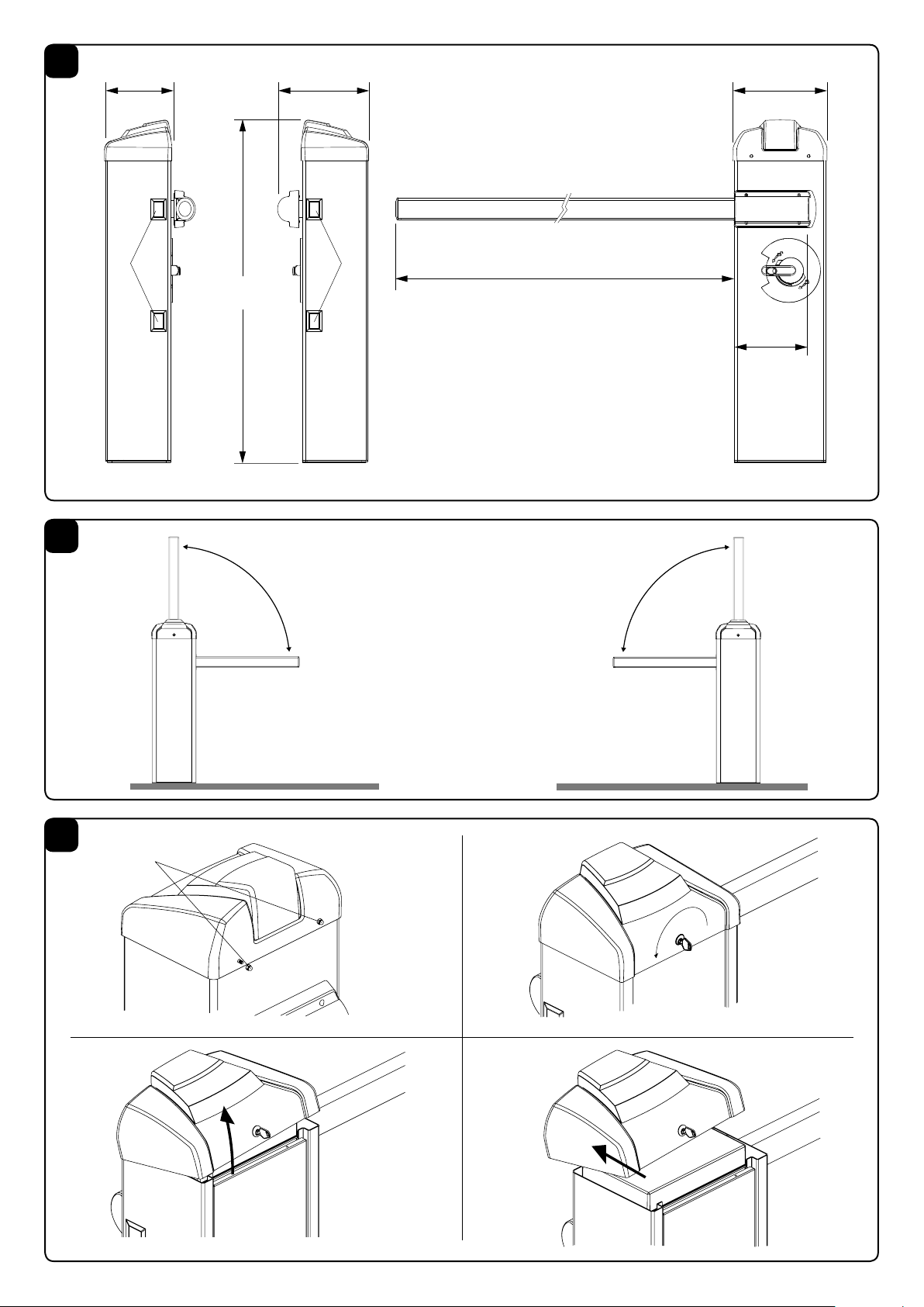
DIMENSIONI
FIG.1
Dimensioni di ingombro espresse in mm.
La lunghezza dell'asta può variare da un minimo di 3m ad
un massimo di 5m.
Poichè circa 25cm sono necessari al fissaggio dell'asta sulla
barriera ne risulta un passaggio utile variabile da 2,75m a
4,75 come evidenziato in Fig.1
Sulla barriera sono previste delle predisposizioni per acces-
sori opzionali (fotocellule, selettori, ecc), applicare le apposite
mascherine di copertura fornite in dotazione (Rif. A).
BARRIERA DESTRA/SINISTRA
FIG.2
La barriere EVA.5 viene normalmente fornita nella versione
con apertura destra (Fig. 2 EVA.5 RIGHT).
E' comunque possibile con poche semplici operazioni, mo-
dificare una barriera con apertura destra per ottenere una
barriera con apertura sinistra (Fig. 2 EVA.5 LEFT).
APERTURA
FIG.3
L'accesso alle parti elettriche e meccaniche della barriera è
protetto da una chiusura a serratura con chiave personaliz-
zata, procedere come segue:
1 rimuovere i due dadi D
2 inserire la chiave nella serratura sul lato della porta, e ruo-
tarla in senso antiorario
3 alzare la parte frontale del coperchio
4 sfilare il coperchio
E' ora possibile accedere alla centrale di comando, posizio-
nata sotto il coperchio e alle parti meccaniche della barriera,
rimuovendo la portina frontale.
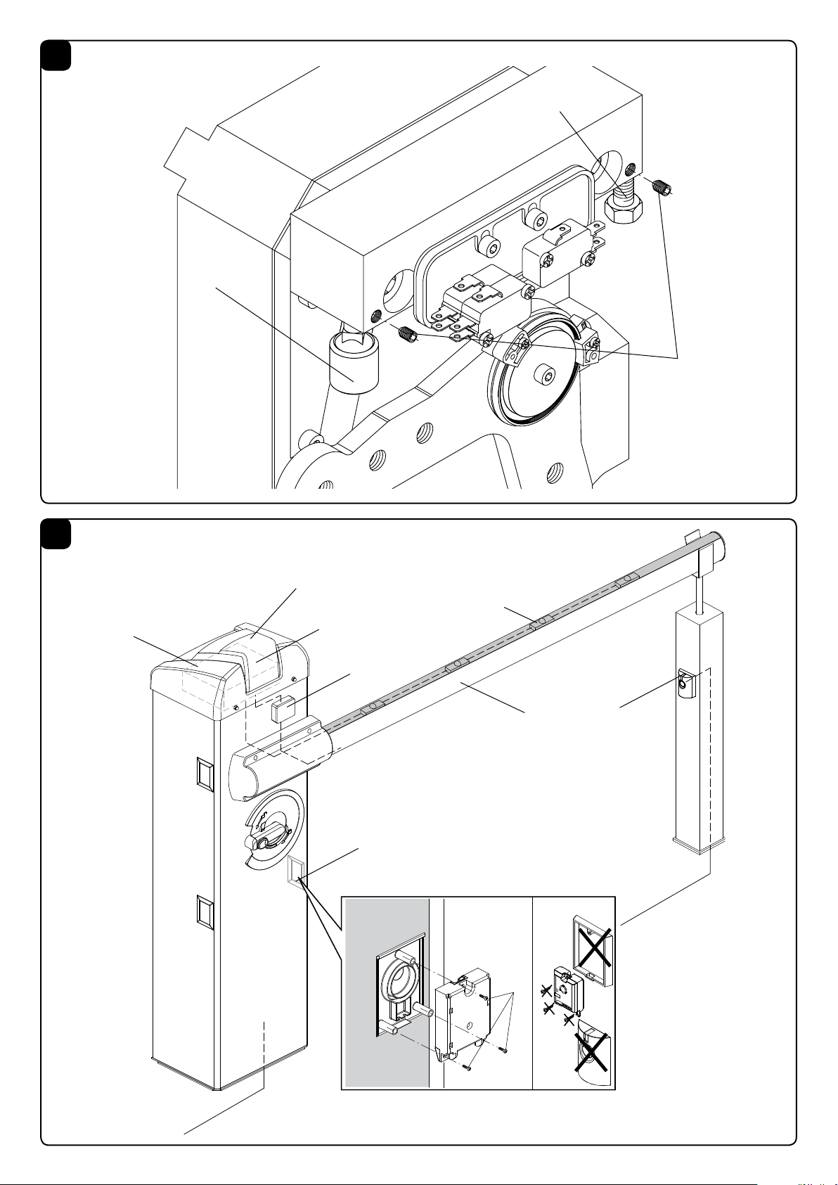
PREDISPOSIZIONE BARRIERA
DESTRA-SINISTRA
FIG.4
Nel caso si renda necessario invertire il senso di apertura,
procedere come segue, in caso contrario passare al para-
grafo successivo:
• scaricarecompletamentelamolla,svitandola,esganciarla
dalla leva di ancoraggio "L"
• conriferimentoallaFig.4,invertirelaposizionedeifermi
meccanici "F1" e "F2". Allentare i rispettivi grani di bloc-
caggio prima di svitare i fermi (vedi paragrafo REGOLA-
ZIONE FERMI MECCANICI)
• sbloccareilmotoriduttore(vedi"Manovramanuale")in
modo da rendere libero il movimento della leva di aggan-
cio L.
• a seconda della lunghezza dell'asta e degli accessori
utilizzati, scegliere il punto di aggancio corretto, come
inidcato nel paragrafo Posizionamento della molla e ac-
cessori utilizzabili.
• agganciarelamollanellanuovaposizione,inFig.4sono
evidenziate le differenze tra una barriera destra e una
barriera sinistra.
• nella centrale di comando invertire i collegamenti mo-
tore e i finecorsa SWC (finecorsa chiusura) e SWC-R
(finecorsa rallentamento chiusura).

10
POSA DELLA PIASTRA DI FONDAZIONE
VE.PS (OPZIONALE)
FIG.5
Dopo aver predisposto il passaggio dei cavi (alimentazione
di rete, accessori, ecc), posizionare la piastra di fondazione
facendo riferimento alle quote indicate.
In dotazione sono fornite delle staffe a cementare (rif.S) da
fissare alla piastra di fondazione mediante 4 viti M12x50
(rif.V).
Verificare che la piastra di fondazione sia perfettamente a
livello (rif L), quindi fissare la barriera per mezzo dei dadi D
e relative rondelle R
POSIZIONAMENTO DELLA MOLLA
E ACCESSORI UTILIZZABILI
FIG.6
In base alla lunghezza dell'asta ed al tipo di accessori in-
stallati, prima di procedere al tensionamento della molla, è
necessario scegliere il corretto punto di aggancio della molla
stessa alla leva.
Il punto di aggancio corretto, ("A", "B" e "C"), deve essere
scelto nella tabella 1 in base alla lunghezza dell'asta ed al
tipo di accessori che si intendono installare.
FISSAGGIO DELL'ASTA
FIG.7
Eventuali accessori per l'asta (profili di protezione, luci, bordo
sensibile, rastrelliera, ecc.) vanno installati prima di fissare
l'asta, consultate le istruzioni specifiche.
Successivamente fissare l'asta alla piastra P utilizzando la
staffa S e le 6 viti con relative rondelle, utilizzando anche la
piastrina T.
Applicare il carter di copertura in plastica C.
MANOVRA MANUALE DI EMERGENZA
FIG.8
In caso di assenza di alimentazione di rete o di funziona-
mento anomalo, è possibile sbloccare l'asta e manovrarla
manualmente:
• Inserirelachiavepersonalizzatanellalevadisbloccoe
ruotarla in senso orario.
• Ruotare la leva di sblocco in senso antiorario no a
sbloccare l'asta, in modo da renderla manovrabile ma-
nualmente.
• Perripristinareilfunzionamentoautomatico,ruotarela
leva in senso orario fino al blocco della stessa, ripristi-
nando la posizione iniziale.
EQUILIBRATURA
FIG.9
Per un buon funzionamento della barriera è fondamentale
che l’asta sia opportunamente equilibrata dall’azione della
molla concorrente.
Per verificare ciò agire come segue.
• Controllarechelamollasiaagganciatanelpuntocorretto
alla leva (vedere tabella 1).
• Sbloccaremeccanicamentelabarrieratramitelachiave
di sblocco.
• L'asta correttamente bilanciata deve restare ferma in
qualsiasi punto venga posizionata:
- se tende ad aprire diminuire la tensione della molla
- se tende a chiudere aumentare la tensione della molla
La tensione della molla può essere regolata, avvitando
(rotazione antioraria) o svitando (rotazione oraria) ma-
nualmente la molla stessa. Una volta regolata la tensione
della molla, bloccarla portando il dado "D" in battuta sul
tappo T.
MOVIMENTI E TEMPI DI LAVORO
Durante la manovra di apertura Fig. 10:
Partendo dal punto di chiusura "C" la sbarra inizia la manovra
di apertura ed arriva fino al punto "SWO-R" di intervento
del finecorsa di apertura con una velocità impostabile dalla
centrale di comando.
La sbarra percorre lo spazio restante (evidenziato in Fig.
Fig.10) a velocità ridotta per un tempo definito dalla centrale
di comando.
La sbarra arriva quindi al punto A completando il movimento
di apertura.
Durante la manovra di chiusura Fig. 11:
La sbarra parte dal punto di apertura "A" ed arriva fino al
punto "SWC-R" di intervento del finecorsa di rallentamento
TAB.1
EVA.5
Lunghezza asta (m)
Accessori applicati 3 3,5 4 4,5 5
EVA5.A C C B B A
EVA5.A + VE.RAST C B B A A
EVA5.A + VE.AM C C B B A
EVA5.A + VE.RAST + VE.AM C B B A A
EVA5.A + SC.RES C B B A A
EVA5.A + SC.RES + VE.AM C B B A A
Legenda
EVA5.A Asta con gomma e cupolino.
VE.RAST Rastrelliera in alluminio.
VE.AM Appoggio mobile per asta.
SC.RES Bordo sensibile resistivo (conforme all’allegato 4 della
Direttiva Macchine).
Attenzione:
L'installazione della VE.RAST pregiudica l'uso della SC.RES e viceversa.
L'installazione del kit luci EVA.L non influenza il bilanciamento dell'asta
C
B
A

11
con una velocità impostabile dalla centrale di comando.
Dall'intervento del finecorsa di rallentamento inizia il ciclo di
frenatura che si conclude esclusivamente con l'intervento
del finecorsa di chiusura nel punto "C".
La centrale di comando verifica l'avvenuta commutazione
del finecorsa "SWC" ed è in grado di compensare automa-
ticamente eventuali variazioni dovute ad esempio a differenti
condizioni climatiche.
L'angolo di frenatura evidenziato in Fig.11 è fisso e corri-
sponde a circa 25°.
Le regolazioni delle camme finecorsa, dei trimmer e dei dip-
switch devono essere effettuate facendo riferimento a questi
principi di funzionamento.
REGOLAZIONE CAMME FINECORSA
FIG.12
La regolazione delle camme finecorsa consentono:
Camma O
Anticipare o ritardare l'inizio della fase di rallentamento in
apertura (Fig.10 - punto "SWO-R").
Camma C
Regolare con precisione il punto di arresto in chiusura (Fig.11
- punto "C").
Nota: La camma C prima di attivare il finecorsa di chiusura,
dà inizio alla fase di rallentamento attivando il finecorsa
(Fig.11 - punto "SWC-R").
Regolare le camme, facendo riferimento alla Fig.12:
• AllentarelaviteVdissaggiodellacamma.
• Portarelacammadiaperturaochiusuranellaposizione
desiderata.
• FissareaviteVdissaggiodellacamma.
REGOLAZIONE FERMI MECCANICI
FIG.13
Il movimento inerziale dell'asta successivo all'arresto del mo-
tore viene bloccato utilizzando i fermi meccanici regolabili.
Dopo aver regolato la camma finecorsa di apertura/chiusura,
portare il rispettivo fermo meccanico di chiusura in battuta
sulla leva.
Il fermo meccanico in apertura F2 è di tipo ammortizzato.
Facendo riferimento alla Fig.13:
• AllentareilgranoGdiblocco
• Avvitare/svitareil fermo meccanicono adottenere la
posizione di intervento desiderata
• Fissareilgranodiblocco
Nel caso di inversione del verso di apertura è necessario
invertire la posizione dei fermi.
SCHEMA IMPIANTO ELETTRICO
FIG.14
Rappresenta un esempio di installazione della barriera con
alcuni dei principali accessori.
LEGENDA
1 Centrale di comando DA.24V
2 Fotocellula ricevitore
3 Fotocellula trasmettitore
4 Batterie di emergenza installabili allinterno della scatola
centrale di comando
5 Scheda lampeggiante EVA:LAMP
6 Consta pneumatica SC.RES
7 Circuito SC.E di intrfaccia SC.RES/DA:24V
Per l'installazione ed il collegamento dei vari accessori con-
sultare le istruzioni specifiche.
ATTENZIONE
La polizza RC prodotti, che risponde di eventuali danni a
cose o persone causati da difetti di fabbricazione, richiede
la conformità dell’impianto alle normative vigenti e l’utilizzo
di accessori originali Benincà.

12
The product shall not be used for purposes or in ways
other than those for which the product is intended for and
as described in this manual. Incorrect uses can damage
the product and cause injuries and damages.
The company shall not be deemed responsible for the
non-compliance with a good manufacture technique of
gates as well as for any deformation, which might occur
during use.
Keep this manual for further use.
Qualified personnel, in compliance with regulations in force,
shall install the system.
Packaging must be kept out of reach of children, as it can
be hazardous. For disposal, packaging must be divided
the various types of waste (e.g. carton board, polystyrene)
in compliance with regulations in force.
The installer must supply all information on the automatic,
manual and emergency operation of the automatic system
and supply the end user with instructions for use.
WARNING
•An omnipolar switch/section switch with remote
contact opening equal to, or higher than 3mm
must be provided on the power supply mains..
Make sure that before wiring an adequate differential
switch and an overcurrent protection is provided.
Pursuant to safety regulations in force, some types of in-
stallation require that the gate connection be earthed.
During installation, maintenance and repair, cut off power
supply before accessing to live parts.
Descriptions and figures in this manual are not binding.
While leaving the essential characteristics of the product
unchanged, the manufacturer reserves the right to modify
the same under the technical, design or commercial point
of view without necessarily update this manual.
EC Declaration of Conformity
(Directive 2004/108/EC(EMC); 2006/95/EC (LVD
:Manufacturer
Automatismi Benincà SpA.
Address:
Via Capitello, 45 - 36066 Sandrigo (VI) – Italy
It is hereby stated that the product
operator for road gates
EVA.5.
is compliant with provisions set forth in the following EC Directives:
- DIRECTIVE 2004/108/EC OF THE EUROPEAN PARLIAMENT AND OF THE COUNCIL of 15 December 2004, on the harmo-
nisation of the laws of Member States relating to electromagnetic compatibility and which cancels Directive 89/336/EEC, according to the
following harmonised regulations: EN 61000-6-2:2005, EN 61000-6-3:2007.
- DIRECTIVE 2006/95/EC OF THE EUROPEAN PARLIAMENT AND OF THE COUNCIL of 12 December 2006, on the harmoni-
sation of the laws of Member States relating to electrical equipment designed for use with certain voltage limits, according to the following
harmonised regulations: EN 60335-1:2002 + A1:2004 + A11:2004 + A12:2006 + A2:2006 + A13:2008; EN 60335-2-103:2003.
- DIRECTIVE 2006/42/EC OF THE EUROPEAN PARLIAMENT AND OF THE COUNCIL of 17 May 2006, on machinery, which
amends Directive 95/16/EC, and complies with the requisites for the “partly completed machinery (almost machinery)” set forth in the
EN13241-1:2003 regulation.
• Moreover, Automatismi Benincà SpA declares that the pertaining technical documentation has been drawn up in compliance with
Attachment VII B of the 2006/42/ EC Directive and that the following requirements have been complied with: 1.1.1 - 1.1.2 - 1.1.3 - 1.1.5
- 1.2.1 - 1.2.3 - 1.2.6 - 1.3.1 - 1.3.2 - 1.3.3 - 1.3.4 - 1.3.7 - 1.3.9 - 1.5.1 - 1.5.2 - 1.5.4 - 1.5.5 - 1.5.6 - 1.5.7 - 1.5.8 - 1.5.10 - 1.5.11 - 1.5.13
- 1.6.1 - 1.6.2 - 1.6.4 - 1.7.2 - 1.7.4 - 1.7.4.1 - 1.7.4.2 - 1.7.4.3.
• The manufacturer undertakes that information on the “partly completed machinery” will be sent to domestic authorities. Transmission
ways are also included in the undertaking, and the Manufacturer’s intellectual property rights of the “almost machinery” are respected.
• It is highlighted that commissioning of the “partly completed machinery” shall not be provided until the final machinery, in which it
should be incorporated, is declared compliant, if applicable, with provisions set forth in the Directive 2006/42/EC on Machinery.
• Moreover, the product, as applicable, is compliant with the following regulations:
EN 12445:2002, EN 12453:2002, EN 12978:2003.
.Benincà Luigi, Legal Ofcer
..Sandrigo, 06/06/2012

13
INTRODUCTION
Thank you for choosing our EVA.5 road gate.
All items included in Benincà’s wide product range stem
from twenty year of our experience in the sector of automatic
systems, always striving to find new materials and advanced
technologies.
For this reason, nowadays we are able to offer you extremely
reliable products that, thanks to their power, efficiency and
long-lasting features, entirely meet the end user’s require-
ments.
All our products are covered by a guarantee.
Furthermore, an R.C. insurance policy signed with a primary
insurance company, covers any injuries or damages caused
by manufacturing faults.
GENERAL INFORMATION
Of rugged construction, with an innovative and pleasant
design, the road barriers EVA are suited for intensive use
thanks to their 24VDC motor. This system is very easy to
install and adjust.
Equipped with an easy-to-use manual release, the barrier is
preset to assemble buffer batteries to allow its operation in
the event of power failure.
The arm in paint aluminium allows for the housing of any
accessories, as well as forewarning and safety devices. In
the event the arm hits an obstacle, an amperometric sensor
causes the movement reversion immediately.
The control unit is placed on the upper side of the barrier to
facilitate wire connections.
SPECIFICATION EVA.5
Power supply
Motor power supply
Power drawn
Current absorption
Torque
Jogging
Protection class
Operating temperature
Noise
Lubrication
Weight
230Vac 50Hz
24Vdc
310 W
1,6 A
205 Nm
Intensive use
IP44
-20°C / +50°C
<70 dB
Agip GR MU EP/2
55kg
OPENING SPEED
Motor power
supply
Opening time
(s)
Closing time
(s)
26 Vdc 3 4
23 Vdc 4 5
18 Vdc 5 6
The opening time of the road barrier changes according to the supply
voltage selected on the transformer of the control unit.
Times shown include braking.
DIMENSIONS
FIG.1
Overall dimensions are expressed in mm.
The road barrier length ranges from 3m minimum to 5m
maximum.
As about 25cm are required to fix a road barrier, a useful
opening of passage, ranging from 2.75m to 4.75, will be
available, as shown in Fig.1
Optional accessories can be fitted onto be barrier (photo-
cells, selector, etc.). For assembly, apply the special covers
supplied (Rif. A).
RIGHT/LEFT-HAND OPENING OF THE BARRIER
FIG.2
The EVA.5 road traffic barrier is usually supplied in the right
opening version (Fig. 2 EVA.5 RIGHT).
With a few, simple operations, it is however possible to modify
a right-side oapening road barrier into a left-side one (Fig.2
EVA.5 LEFT).
OPENING
FIG.3
The access to the electric and mechanical components of
the road barrier is protected by a lock with customized key.
Proceed as follows:
1 loosen the two nuts D
2 introduce the key in the lock on the side of the door and
turn it anti-clockwise
3 lift the front cover
4 remove the cover
By removing the front door it is now possible to reach both
the control unit, that is placed under the cover, and the me-
chanical parts of the road barrier.
PREPARATION OF A RIGHT-HAND OR
LEFT-HAND ROAD BARRIER
FIG.4
If the opening direction reversion is required, proceed as
follows. If it is not necessary, go to the next section:
• Entirelyunloadthespringbylooseningitandunhooking
it from the “L” anchoring lever
• withreferencetoFig.4,invertthepositionofthe“F1”and
“F2” mechanical stoppers. Before loosening the stoppers,
back-off the related locking grains (see section HOW TO
ADJUST THE MECHANICAL STOPERS)
• unlockthegearedmotor(see“ManualOperation”)insofar
as to render the L hooking lever idle.
• accordingtothelengthoftheroadbarrierarmandac-
cessories used, choose the correct hooking position,
as indicated in paragraph “Positioning of the spring and
accessories”.
• hook the spring in the new position. Fig. 4 shows the
differences between a right-hand road barrier and a left-
hand one.
• inthecontrolunit,invertthewiresofmotor,aswell
asSWClimitswitch(closinglimitswitch)andSWC-R
limitswitch(closurebrakinglimitswitch).
INSTALLATION OF THE FOUNDATION PLATE
VE.PS (OPTIONAL)
FIG.5
After preparing the cable laying (mains power supply, acces-
sories, etc.), place the foundation plate keeping to dimensions
indicated.
Brackets to be cemented are supplied with the system (ref.
S). The brackets must be fitted to the foundation plate by
means of 4 screws M12x50 (ref. V).
Check that the foundation plate is perfectly flat (ref. L), then
fix the road barrier by means of nuts D and corresponding
washers R.

14
POSITIONING OF THE SPRING
AND ACCESSORIES
FIG.6
According to the length of the beam and the type of accesso-
ries installed, before tensioning the spring, the correct point
to hook the spring to the lever must be selected.
The correct hooking point (“A”, “B” and “C”), must be se-
lected by taking account of table 1, according to the beam
length and the type of accessories to be installed.
HOW TO FIX THE BEAM
FIG.7
Any accessories for the beam (protection edges, lights, pneu-
matic safety edges, rack, etc. ) are installed before fitting the
beam. See relevant instructions.
Fit the beam to plate P by using bracket S and both the 6
screws with the corresponding washers, and plate T.
Apply the removable plastic cover C.
EMERGENCY MANUAL OPERATION
FIG.8
Should a power failure occur or in the event of faults in the
system, the beam can be released and moved by hand:
• Introducethecustomizedkeyinthereleaseleverandturn
it clockwise.
• Turnthereleaseleveranti-clockwiseuntilthebeam is
released and it can be opened and closed by hand.
• Toresettheautomaticoperation,turntheleverclockwise
until the beam is released. Reset the initial position.
BALANCING
FIG.9
For a good operation of the road barrier, the beam must be
suitably balanced by the spring.
To check the correct balancing, proceed as follows.
• Checkthatthespringiscorrectlyhookedtothelever(see
table 1).
• Mechanicallyreleasetheroadbarrierthroughtherelease
key.
• Theroadbeam,correctlybalanced,shouldremainstillin
TAB.1
EVA.5
Bar length (m)
Accessories for use 3 3,5 4 4,5 5
EVA5.A C C B B A
EVA5.A + VE.RAST C B B A A
EVA5.A + VE.AM C C B B A
EVA5.A + VE.RAST + VE.AM C B B A A
EVA5.A + SC.RES C B B A A
EVA5.A + SC.RES + VE.AM C B B A A
Key
EVA5.A Shank with rubber and upper profile.
VE.RAST Aluminium skirt.
VE.AM Mobile support for bar.
SC.RES Sensitive resistive edge (complying with annexe 4
of the Machines Directive).
Attention:
The installation of the VE.RAST interferes with the use of the SC.RES and vice
versa.
The installation of the EVA.L lights kit does not influence the balancing of the bar
any position:
- if it tends to open, reduce the spring tension
- if it tends to close, increase the spring tension
The spring tension can be adjusted by tightening (anti-
clockwise rotation) or loosening (clockwise rotation) the
spring by hand. Once the spring tension is adjusted, lock
it by moving the nut “D” in contact with cap T.
MOVEMENTS AND OPERATING TIME
During opening as per Fig. 10:
Starting from the closing position “C”, the beam starts its
opening until it reaches the “SWO-R” point, where the ope-
ning limit switch triggers. The opening speed can be adjusted
through the control unit.
The beam moves for the remaining space (as shown in Fig.10)
at a reduced speed, for a time preset by the control unit.
Therefore, the barrier reaches point A, by completing the
opening movement.
During closure, as per Fig. 11:
The beam starts moving from the opening point “A” and stops
at “SWC-R “ point, when the braking limit switch triggers. The
closing speed can be preset through the control unit.
After activation of the braking limit switch, the braking cycle
starts, ending only when the closing limit switch “C” trig-
gers.
The control unit checks the activation of the “SWC” limit
switch and it is able to automatically offset any changes due
to different weather conditions, for example.
The braking angle shown in Fig.11 is fixed at around 25°.
Adjustments of the limit switch cams, trimmers and dip-
switches should be carried out by referring to these operating
principles.
ADJUSTMENT OF LIMIT SWITCH CAMS
FIG.13
The adjustment of the limit switch cams allow for the fol-
lowing:
Cam O
To advance or delay the starting of braking in the opening
C
B
A

15
phase (Fig.10 - “SWO-R” point).
Cam C
To previously adjust the stop point in the closing phase
(Fig.11 - “C” point).
Note: before activating the closing limit switch, the cam C
starts braking by triggering the limit switch (Fig.11 - point
“SWC-R”).
Adjust cams by referring to Fig.12:
• LoosenscrewVofcamtting.
• Movetheopeningorclosingcaminthedesiredposition.
• TightenthettingscrewVofthecam.
HOW TO ADJUST
THE MECHANICAL STOPPERS
FIG.13
After the motor stop, the inertial movement of the beam is
blocked thanks to adjustable mechanical stoppers.
After adjusting the opening/closing limit switch cam, move
the related closing mechanical stopper against the lever.
The opening mechanical stopper F2 is of the amortized
type.
By taking Fig.13as a reference:
• LoosenthelockgrainG
• Tighten/loosenthemechanicalstopuntilthedesiredac-
tivation position is reached
• Tightenthelockgrain
Should an opening direction reversion is required, the position
of the stoppers must be inverted.
WIRE DIAGRAM
FIG.14
This figure shows an installation example of road barrier with
its main accessories.
KEY
1 DA.24V control unit
2 Receiver photocell
3 Transmitter photocell
4 Emergency batteries that can be installed inside the con-
tainer of the control unit
5 EVA:LAMP flashing light card
6 SC.RES pneumatic safety edge
7 SC.E circuit of interface SC.RES/DA:24V
To install and connect the various accessories, see related
instructions.
WARNING
The RC product insurance policy, which covers any injuries
or damages to objects caused by manufacturing defects,
requires the use of Benincà’s original accessories.

16
Das Produkt darf nicht für andere Zwecke oder auf andere
Weise verwendet werden, als in der vorliegenden Anleitung
beschrieben. Ein ungeeigneter Gebrauch kann das Produkt
beschädigen und eine Gefahr für Personen und Sachen
darstellen.
Wir übernehmen keinerlei Haftung für Schäden, die sich aus
einer unsachgerechten Montage der Tore und aus daraus
folgenden Verformungen ergeben können.
Bewahren Sie dieses Handbuch für Nachschlagzwecke auf.
Die Installation darf nur von qualifizierten Fachleuten laut den
geltenden Vorschriften vorgenommen werden.
Das Verpackungsmaterial fern von Kindern halten, da es eine
potentielle Gefahr darstellt. Das Verpackungsmaterial nicht ins
Freie werfen, sondern je nach Sorte (z.B. Pappe, Polystyrol)
und laut den örtlich geltenden Vorschriften entsorgen.
Der Installateur hat dem Benutzer alle Informationen über den
automatischen, manuellen Betrieb sowie den Not-Betrieb
der Automatik zusammen mit der Bedienungsanleitung zu
liefern.
HINWEISE
•Das Stromnetz muss mit einem allpoligen Schalter
bzw. Trennschalter ausgestattet sein, dessen Kon-
takte einen Öffnungsabstand gleich oder größer als
3 aufweisen.
Kontrollieren, ob der elektrischen Anlage ein geeigneter
Differentialschalter und ein Überspannungsschutzschalter
vorgeschaltet sind.
Einige Installationstypologien verlangen den Anschluss des
Flügels an eine Erdungsanlage laut den geltenden Sicherhei-
tsnormen.
Während der Installation, der Wartung und der Reparatur, die
Anlage stromlos machen bevor an den elektrischen Teilen
gearbeitet wird.
Die in diesem Handbuch enthaltenen Beschreibungen und
Abbildungen sind nicht verbindlich. Ausgenommen der
Haupteigenschaften des Produkts, behält sich der Hersteller
das Recht vor eventuelle technische, konstruktive oder kom-
merzielle Änderungen vorzunehmen ohne dass er vorliegende
Veröffentlichung auf den letzten Stand bringen muss.
EG-Konformitätserklärung
Erklärung gemäß Richtlinie 2004/108/CE(EMV); 2006/95/CE(LVD)
Hersteller:
Automatismi Benincà SpA
Adresse:
Via Capitello, 45 - 36066 Sandrigo (VI) - Italien
Erklärt, dass das Produkt:
Wir erklären, dass: Antriebe für Straßensperren Modell
EVA.5
folgenden EG-Richtlinien entspricht:
• RICHTLINIE 2004/108/EG DES EUROPÄISCHEN PARLAMENTS UND DES RATES vom 15. Dezember 2004 zur Angleichung
der Rechtsvorschriften der Mitgliedstaaten über die elektromagnetische Verträglichkeit und zur Aufhebung der Richtlinie 89/336/EWG,
gemäß nachstehenden Normen: EN 61000-6-2:2005, EN 61000-6-3:2007.
• RICHTLINIE 2006/95/EG DES EUROPÄISCHEN PARLAMENTS UND DES RATES vom 12. Dezember 2006 zur Angleichung
der Rechtsvorschriften der Mitgliedstaaten betreffend elektrische Betriebsmittel zur Verwendung innerhalb bestimmter Spannungsgrenzen,
gemäß nachstehenden Normen: EN 60335-1:2002 + A1:2004 + A11:2004 + A12:2006 + A2:2006 + A13:2008; EN 60335-2-103:2003.
• RICHTLINIE 2006/42/EG DES EUROPÄISCHEN PARLAMENTS UND DES RATES vom 17. Mai 2006 über Maschinen, zur
Aufhebung der Richtlinie 95/16/EG, gemäß Anforderungen für „unvollständige Maschinen“ und nachstehender Norm: EN13241-1:2003.
• Automatismi Benincà SpA erklärt, dass die technischen Unterlagen gemäß Anhang VII Teil B der Richtlinie 2006/42/EG erstellt
wurden und dass das Produkt folgenden Anforderungen entspricht: 1.1.1 - 1.1.2 - 1.1.3 - 1.1.5 - 1.2.1 - 1.2.3 - 1.2.6 - 1.3.1 - 1.3.2 - 1.3.3 -
1.3.4 - 1.3.7 - 1.3.9 - 1.5.1 - 1.5.2 - 1.5.4 - 1.5.5 - 1.5.6 - 1.5.7 - 1.5.8 - 1.5.10 - 1.5.11 - 1.5.13 - 1.6.1 - 1.6.2 - 1.6.4 - 1.7.2 - 1.7.4 - 1.7.4.1
- 1.7.4.2 - 1.7.4.3.
• Der Hersteller verpflichtet sich die Informationen zu der „unvollständigen Maschine“ einzelstaatlichen Stellen auf begründetes Verlangen
zu übermitteln. Durch die Übermittlung bleibt das intellektuelle Eigentum des Herstellers der „unvollständigen Maschine“ unberührt.
• Diese „unvollständige Maschine“ darf erst dann in Betrieb genommen werden, wenn gegebenenfalls festgestellt wurde, dass die Ma-
schine, in die die unvollständige Maschine eingebaut werden soll, den Bestimmungen der Maschinenrichtlinie 2006/42/EG entspricht.
• Das Produkt entspricht außerdem, falls zutreffend, folgenden Normen:
EN 12445:2002, EN 12453:2002, EN 12978:2003.
Benincà Luigi, Rechtsvertreter
Sandrigo, 06/06/2012.

17
GRÖSSE
ABB.1
Außenmaße in mm.
Die Schrankenarmlänge beträgt mindestens 3 m und ma-
ximal 5 m.
Da zur Befestigung des Arms an der Schranke 25 cm benötigt
werden, beträgt die nützliche Länge 2,75 m bis 4,75 m, wie
in Abb. 1 gezeigt.
Die Schranke ist zudem zur Montage von anderen, auf
Wunsch erhältlichen Zubehörteilen (Fotozelle, Wahlschalter
usw.) vorbereitet. Diese Verbindungsstellen werden, falls
nicht verwendet, mit den mitgelieferten Abdeckungen (Ref.
A) verschlossen.
RECHTS-/LINKSSEITIGE SCHRANKE
ABB.2
Die Schranke EVA.5 wird i.d.R. mit Öffnung nach rechts
geliefert (Abb. 2 EVA.5 RIGHT).
Die Öffnungsrichtung kann jedoch auf sehr einfache Wiese
von rechts auf links geändert werden (Abb. 2 EVA.5 LEFT).
ÖFFNEN
ABB.3
Der Zugang zu den elektrischen und mechanischen Teilen
der Schranke, ist durch ein Schloss mit entsprechendem
Schlüssel blockiert. Folgendermaßen vorgehen:
1 Die beiden Muttern D abschrauben
2 Den Schlüssel in das Schloss an der Türseite stecken und
gegen den Uhrzeigersinn drehen
3 Das Frontteil des Deckels heben
4 Den Deckel abziehen
Nun ist der Zugang zur Steuereinheit frei, die sich unterhalb
des Deckels befindet. Die mechanischen Teile der Schranken
können durch das Abnehmen der Frontklappe freigesetzt
werden.
RECHTS-/LINKSSEITIGE
SCHRANKE VORBEREITEN
ABB.4
Falls die Öffnungsrichtung geändert werden muss, folgen-
dermaßen vorgehen, anderenfalls die Anweisungen des
nachfolgenden Paragraphen befolgen.
• DieFedervollständigdurchAbschraubenentlastenund
aus der Verankerung „L“ am Hebel herausnehmen.
• GemäßAbb.4diePositiondermechanischenFeststellvor-
richtungen „F1“ und „F2“ umkehren. Die entsprechenden
Befestigungsstifte lockern, bevor die Feststellvorrichtun-
gen abgeschraubt werden (siehe Paragraph EINSTELLEN
DER MECHANISCHEN FESTSTELLVORRICHTUNGEN)
• Den Getriebemotor entsichern (siehe „Handbetrieb“),
so dass der Befestigungshebel L frei bewegt werden
kann.
• DierichtigeBefestigungspositionjenachArmlängeund
gewähltem Zubehör wählen. Siehe Paragraph „Position
der Feder und verwendbares Zubehör“.
• Die Feder an der neuen Position einhaken. Die Abb.
4zeigt den Unterschied zwischen der rechtsseitigen und
linksseitigen Schranke.
• AnderSteuereinheitdieAnschlüssedesMotorsund
derEndschalterSWC(EndschalterfürdasSchließen)
undSWC-R(EndschalterfürdieGeschwindigkeitsab-
nahmebeimSchließen)umkehren.
EINLEITUNG
Wir danken Ihnen dafür, daß Sie sich für die EVA.5 Straßen-
sperre entschieden haben.
Alle Artikel der breiten Produktpalette von Benincà sind das
Ergebnis einer zwanzigjährigen Erfahrung auf dem Gebiet
der Automationen und der ständigen Forschung nach neuen
Materialien und den neusten Technologien.
Daher sind wir in der Lage äußerst zuverlässige Produkte
anzubieten, die durch ihre Leistung, Funktionstüchtigkeit
und Lebensdauer allen Erfordernissen des Endkunden na-
chkommen können.
Alle unsere Produkte sind durch eine Garantie gedeckt.
Zudem deckt eine Haftpflichtversicherung, die mit einer
wichtigen Versicherungsgesellschaft abgeschlossen worden
ist, eventuelle Schäden oder Unfälle die sich aus Produktion-
smängeln ergeben sollten.
ALLGEMEINE INFORMATIONEN
Die Straßenschranken EVA sind robust und gleichzeitig
innovativ und schön im Design und eignen sich, dank dem
Motor zu 25 Vdc, einem intensiven Gebrauch. Sie sind leicht
zu installieren und einzustellen.
Die manuelle Entriegelung ist einfach und intuitiv und es
besteht die Möglichkeit Pufferbatterien zu montieren, die
es gestatten die Schranke auch bei Stromausfall zu betrei-
ben.
Der Schrankenarm aus lackiertem Aluminium ist vorbereitet,
um das Zubehör sowie die Signal- und Sicherheitsvorrichtun-
gen, zu montieren. Wenn der Schrankenarm ein Hindernis
berührt, kehrt ein Stromsensor die Bewegungsrichtung
unverzüglich um.
Die Steuereinheit ist am oberen Teil der Schranke montiert,
was die elektrischen Anschlüsse erleichtert.
TECHNISCHE DATEN EVA.5
Speisung
Motorenspeisung
Leistungsaufnahme
Stromaufnahme
Drehmoment
Intermittierender Betrieb
Schutzklasse
Betriebstemperatur
Geräuschpegel
Schmierung
Gewicht
230Vac 50Hz
24Vdc
310 W
1,6 A
205 Nm
intensiverGebrauch
IP44
-20°C / +50°C
<70 dB
Agip GR MU EP/2
55kg
ÖFFNUNGSGESCHWINDIGKEIT
Speisung
Motor
Öffnungszeit
(s)
Schließzeit
(s)
26 Vdc 3 4
23 Vdc 4 5
18 Vdc 5 6
Die Öffnungsgeschwindigkeit der Schranke ist von der Speisespannung
abhängig, die am Trafo der Steuereinheit eingestellt wird.
Die angegebenen Zeiten berücksichtigen die Geschwindigkeitsabnah-
men..

18
VERLEGEN DER FUNDAMENTPLATTE
VE.PS (OPTION)
ABB.5
Nachdem die Kabelverlegung vorbereitet worden ist (Strom-
versorgung, Zubehör usw.), die Fundamentplatte laut den
angegebenen Maßen positionieren.
Die mitgelieferten Bügel mit den 4 Schrauben M12x50 (Ref.
V) an die Fundamentplatte befestigen und mit Beton veran-
kern (Ref. S).
Sicherstellen, dass die Fundamentplatte einwandfrei ausge-
richtet ist (Ref.L) und die Schranke mit den Muttern D und
den Unterlegscheiben R befestigen.
POSITION DER FEDER
UND DES ZUBEHÖRS
ABB.6
Je nach Schrankenarmlänge und dem installierten Zubehör,
die Feder an der geeigneten Stelle am Hebel einsetzen und
danach spannen.
Die richtige Federposition („A“, „B“ und „C“) anhand der Ta-
belle 1, je nach Armlänge und gewähltem Zubehör wählen.
BEFESTIGUNG DES SCHRANKENARMS
ABB.7
Das gewünschte Zubehör (Schutzprofile, Leuchten, Nähe-
rungsflanke, Abhängung usw.) muss vor der Befestigung
des Schrankarms montiert werden. Siehe entsprechende
Anweisungen.
Danach wird der Schrankenarm an die Platte P mit dem
Bügel S und den 6 Schrauben mit Unterlegscheiben und
dem Plättchen T befestigt.
Die beiden Kunststoffabdeckungen C anbringen.
MANUELLE NOTBEDIENUNG
ABB.8
Im Falle eines Stromausfalls oder einer Störung, kann der
Schrankenarm entriegelt und von Hand bewegt werden:
• DenpersonalisiertenSchlüsselindenEntriegelungshebel
stecken den Uhrzeigersinn drehen.
• Den Entriegelungshebel in gegen den Uhrzeigersinn
drehen bis der Schrankenarm entriegelt und von Hand
bewegt werden kann.
• UmdenautomatischenBetriebwiedereinzustellen,den
Hebel Uhrzeigersinn drehen, bis er blockiert und die
Ausgangsposition wieder erreicht ist.
AUSWUCHTEN
ABB.9
Für den einwandfreien Betrieb der Schranke ist es wichtig,
dass der Schrankenarm durch die Gegenkraft der Feder
richtig ausgewuchtet ist.
Zur Kontrolle folgendermaßen vorgehen:
• Kontrollieren, ob die Feder an der richtigen Stelle am
Hebel eingehakt ist (siehe Tabelle 1).
• DieSchrankeüberdenEntriegelungsschlüsselmecha-
nisch entriegeln.
• EinrichtigausgewuchteterSchrankenarmmussinjeder
Position stillstehen:
- Falls er sich weiter öffnet, die Spannung der Feder
verringern
- Falls er sich weiter schließt, die Spannung der Feder
erhöhen
Die Spannung der Feder kann durch Festschrauben
(drehen gegen den Uhrzeigersinn) oder Lockern (drehen
im Uhrzeigersinn) der Feder selbst von Hand eingestellt
werden. Nachdem die Federspannung eingestellt worden
ist, die Mutter „D“ bis zum Anschlag am Verschluss T
festziehen, um die Feder zu blockieren.
BEWEGUNGEN UND BETRIEBSZEITEN
DieSchrankewirdfolgendermaßengeöffnet(Abb.10):
Von der geschlossenen Position „C“ beginnt die Schranke
die Öffnungsbewegung bis sie den Punkt „SWO-R“ erreicht,
an dem der Endschalter der Öffnung einschaltet und die Ge-
schwindigkeit durch die Steuereinheit verlangsamt wird.
Der Schrankenarm bewegt sich nun bei verringerter Ge-
schwindigkeit, für die über die Steuereinheit eingestellte Zeit,
bis zum Ende weiter (Abb. 10).
TAB.1
EVA.5
Stangenlänge (m)
Verwendbares Zubehör 3 3,5 4 4,5 5
EVA5.A C C B B A
EVA5.A + VE.RAST C B B A A
EVA5.A + VE.AM C C B B A
EVA5.A + VE.RAST + VE.AM C B B A A
EVA5.A + SC.RES C B B A A
EVA5.A + SC.RES + VE.AM C B B A A
Legende
EVA5.A
Stangen
mit Gummi-und oberen Profi.
VE.RAST Unterfahrsperre aus Aluminium.
VE.AM Bewegliche Stangenauflage.
SC.RES Resistive Kontaktleiste (gemäß Anlage 4 der Maschinenrichtlinie).
Achtung:
Die Installation der VE.RAST beeinträchtigt den Einsatz der SC.RES und
umgekehrt.
Die Installation des Beleuchtungskits EVA.L beeinflusst nicht die Au-
swuchtung der Stange
C
B
A

19
Wenn der Schrankenarm den Punkt A erreicht, ist der Öff-
nungsvorgang beendet.
DieSchrankewirdfolgendermaßengeschlossen(Abb.
11):
Von der geöffneten Position „A“ beginnt die Schranke die
Schließbewegung bis sie den Punkt „SWC-R“ erreicht, an
dem der Endschalter des Schließvorgangs einschaltet und
die Geschwindigkeit durch die Steuereinheit verlangsamt
wird.
Ab dem Moment wo der Endschalter einschaltet und die Ge-
schwindigkeit verlangsamt wird, wird die Schranke gebremst
bis der Endschalter in der geschlossenen Position – Punkt
„C“ – einschaltet.
Die Steuereinheit prüft das Signal des Endschalters „SWC“
und kann eventuelle Unterschiede, die sich beispielsweise
durch unterschiedliche klimatische Bedingungen ergeben
können, automatisch ausgleichen.
Der Bremswinkel in Abb. 11 ist fest eingestellt und entspricht
etwa 25°.
Die Nocken der Endschalter, der Trimmer und der Dip-
Schalter müssen nach diesem Betriebsprinzip eingestellt
werden.
EINSTELLEN DER ENDSCHALTERNOCKEN
ABB.12
Die Nockeneinstellung an den Endschaltern ermöglicht
Folgendes:
Nocken O
Den Geschwindigkeitsabnahmebeginn beim Öffnen vorver-
stellen oder verzögern (Abb. 10 – Punkt „SWO-R“).
Nocken C
Die geschlossene Position genau einstellen (Abb. 11 – Punkt
„C“).
Bemerkung: Bevor der Nocken C den Endschalter beim
Schließen aktiviert, aktiviert er den Endschalter in Abb. 11
– Punkt „SWC-R“, um die Geschwindigkeit zu verlangsa-
men.
Die Nocken unter Bezugnahme auf Abb. 12 einstellen:
• DieBefestigungsschraubeVdesNockenslockern.
• DenNockenfürÖffnenoderSchließenindiegewünschte
Position bringen.
• DieBefestigungsschraubeVdesNockensfestziehen.
EINSTELLEN DER MECHANISCHEN FEST-
STELLVORRICHTUNGEN
ABB.13
Die Trägheitsbewegung des Schrankenarms nach dem
Anhalten des Motors, wird durch die einstellbaren Feststel-
lvorrichtungen blockiert.
Nachdem der Endschalternocken für Öffnen/Schließen
eingestellt wurde, die entsprechende mechanische Feststel-
lvorrichtung für Schließen am Hebel anschlagen.
Die mechanische Feststellvorrichtung F2 für Öffnen ist
gedämpft.
Unter Bezugnahme auf Abb. 13 folgendermaßen vorge-
hen:
• DenArretierstiftGlockern
• DiemechanischeFeststellvorrichtungauf-/zuschrauben
bis der gewünschte Auslöseposition erreicht ist
• DenArretierstiftGblockieren.
Falls die Öffnungsrichtung umgekehrt wird, muss auch die
Position der Feststellvorrichtungen umgekehrt werden.
SCHALTPLAN
ABB.14
Beispiel zur Installation einer Schranke mit einigen der wich-
tigsten Zubehörteilen.
ERLÄUTERUNG
1 Steuereinheit DA.24V
2 Fotozelle Empfänger
3 Fotozelle Sendegerät
4 Notfallbatterien – können im Inneren der Box der Steue-
reinheit installiert werden
5 Karte für Blinkleuchte EVA:LAMP
6 Pneumatisch betriebene Flanke SC.RES
7 Kreislauf SC.E der Schnittstelle SC.RES/DA:24V.
Weitere Informationen zur Installation und zum Anschluss
der verschiedenen Zubehörteile, sind in den entsprechenden
Anweisungen enthalten.
ACHTUNG!
Die Haftpflichtversicherung die eventuelle Schäden oder
Unfälle die sich aus Produktionsmängeln ergeben sollten,
deckt, verlangt den Einsatz von Originalzubehörteilen von
Benincà.

20
Il est interdit d’utiliser ce produit pour l’utilisation du produit
ou avec des finalités ou modalités non prévues par le présent
manuel. Toute autre utilisation pourrait compromettre l’intégrité
du produit et présenter un danger pour les personnes ou pour
les biens.
Le fabricant décline toute responsabilité en cas d’utilisation
impropre ou d’inobservation de la bonne technique dans la
construction des portails, ainsi que de toute déformation qui
pourrait avoir lieu lors de son utilisation.Toujours conserver la
notice pour toute autre consultation future.
L’installation doit être faite uniquement par un personnel qualifié
dans le respect total des normes en vigueur.
Tenir à l’écart des enfants tous les matériaux d’emballage car
ils représentent une source potentielle de danger. Ne pas di-
sperser les matériaux d’emballage dans l’environnement, mais
trier selon les différentes typologies (i.e. carton, polystyrène) et
les traiter selon les normes locales.
L’installateur doit fournir toutes les informations relatives au
fonctionnement automatique, au déverrouillage d’urgence de
l’automatisme, et livrer à l’utilisateur les modes d’emploi.
REGLES DE SECURITE’
•Prévoir sur le réseau de l’alimentation un interrup-
teur / sectionneur omnipolaire avec distance d’ou-
verture des contacts égale ou supérieure à 3 mm.
Vérifier la présence en amont de l’installation électrique d’un
interrupteur différentiel et d’une protection de surcourant
adéquats.
Certains types d’installation requièrent le branchement du
vantail à une installation de mise à terre satisfaisant les normes
de sécurité e vigueur.
Avant toute intervention, d’installation, réparation et maintien,
couper l’alimentation avant d’accéder aux parties électri-
ques.
Les descriptions et les illustrations présentées dans ce manuel
ne sont pas contraignantes. En laissant inaltérées les carac-
téristiques essentielles du produit, le fabricant se réserve le
droit d’apporter toute modification à caractère technique, de
construction ou commerciale sans s’engager à revoir la cette
publication.
Déclaration CE de conformité
Déclaration conforme aux Directives 2004/108/CE(EMC); 2006/95/CE(LVD)
Fabricant:
Automatismi Benincà SpA
Adresse:
Via Capitello, 45 - 36066 Sandrigo (VI) - Italie
Déclare que le produit:
l’automatisme pour barrières routières modèle
EVA.5.
est conforme aux conditions requises par les Directives CE suivantes:
• DIRECTIVE 2004/108/CE DU PARLEMENT EUROPÉEN ET DU CONSEIL du 15 décembre 2004 concernant le rapprochement
des législations des États membres relatives à la compatibilité électromagnétique et qui abroge la Directive 89/336/CEE, selon les suivantes
normes harmonisées: EN 61000-6-2:2005, EN 61000-6-3:2007.
• DIRECTIVE 2006/95/CE DU PARLEMENT EUROPÉEN ET DU CONSEIL du 12 décembre 2006 concernant le rapprochement des
législations des États membres relatives au matériel électrique destiné à être employé dans certaines limites de tension ,selon les suivantes
normes harmonisées: EN 60335-1:2002 + A1:2004 + A11:2004 + A12:2006 + A2:2006 + A13:2008; EN 60335-2-103:2003.
• DIRECTIVE 2006/42/CE DU PARLEMENT EUROPÉEN ET DU CONSEIL du 17 mai 2006 concernant les machines et qui modie
la Directive 95/16/CE, en respectant les conditions requises pour les “quasi-machines”, selon la norme suivante: EN13241-1:2003.
• Automatismi Benincà SpA déclare, en outre, que la documentation technique pertinente a été constituée conformément à l’annexe
VII B de la Directive 2006/42/CE et que les conditions requises essentielles ci de suite ont été respectées: 1.1.1 - 1.1.2 - 1.1.3 - 1.1.5 -
1.2.1 - 1.2.3 - 1.2.6 - 1.3.1 - 1.3.2 - 1.3.3 - 1.3.4 - 1.3.7 - 1.3.9 - 1.5.1 - 1.5.2 - 1.5.4 - 1.5.5 - 1.5.6 - 1.5.7 - 1.5.8 - 1.5.10 - 1.5.11 - 1.5.13
- 1.6.1 - 1.6.2 - 1.6.4 - 1.7.2 - 1.7.4 - 1.7.4.1 - 1.7.4.2 - 1.7.4.3.
• Le fabricant s’engage à transmettre aux autorités nationales, suite à une demande motivée, les informations concernant la “quasi-
machine”. Cet engagement comprend les modalités de transmission et reste sans préjudices pour les droits de propriété intellectuelle du
fabricant sur la “quasi machine”.
• On communique que la “quasi-machine” ne doit pas être mise en service avant que la machine finale, dans laquelle elle doit être
incorporée, ait été elle même déclarée conforme, le cas échéant, aux dispositions de la Directive 2006/42/CE.
• En outre le produit, exclusivement en ce qui concerne les parties applicables, résulte conforme aux normes suivantes:
EN 12445:2002, EN 12453:2002, EN 12978:2003.
Benincà Luigi, Responsable Légal.
Sandrigo, 06/06/2012.
Other manuals for EVA 5
3
This manual suits for next models
2
Table of contents
Languages:
Other Beninca Automatic Barrier manuals