Beninca ONE.4WB User manual

L8543099
10/2016 rev 1
ONE.4WB
UNIONE NAZIONALE COSTRUTTORI
AUTOMATISMI PER CANCELLI, PORTE
SERRANDE ED AFFINI

2
U6
R A D I O
A D V
CH1 CH2 CH3 CH4
N
F 1
T 1 A
L
SHIELD
ANT
ANT
IN2
IN1
COM
J4
J3
J2
J1
CH1 N.O.
CH1 N.C.
CH20 N.O.
CH2 N.C.
CH3 N.O.
CH3 N.C.
CH4 N.O.
CH4 N.C.

8
ENG WARNING
GENERAL INFORMATIONS
The product shall not be used for purposes or in ways other than those for which the product is intended for
and as described in this manual. Incorrect uses can damage the product and cause injuries and damages.
The company shall not be deemed responsible for the non-compliance with a good manufacture technique
of gates as well as for any deformation, which might occur during use. Keep this manual for further use.
INSTALLER GUIDE
This manual has been especially written to be use by qualified fitters. Installation must be carried out by
qualified personnel (professional installer, according to EN 12635), in compliance with Good Practice and
current code. Make sure that the structure of the gate is suitable for automation. The installer must supply
all information on the automatic, manual and emergency operation of the automatic system and supply the
end user with instructions for use.
GENERAL WARNINGS
Packaging must be kept out of reach of children, as it can be hazardous. For disposal, packaging must be
divided the various types of waste (e.g. carton board, polystyrene) in compliance with regulations in force.
Do not allow children to play with the fixed control devices of the product. Keep the remote controls out of
reach of children. This product is not to be used by persons (including children) with reduced physical, sensory
or mental capacity, or who are unfamiliar with such equipment, unless under the supervision of or following
training by persons responsible for their safety. Apply all safety devices (photocells, safety edges, etc.) re-
quired to keep the area free of impact, crushing, dragging and shearing hazard. Bear in mind the standards
and directives in force, Good Practice criteria, intended use, the installation environment, the operating logic
of the system and forces generated by the automated system. Installation must be carried out using safety
devices and controls that meet standards EN 12978 and EN 12453. Only use original accessories and spare
parts, use of non-original spare parts will cause the warranty planned to cover the products to become null
and void. All the mechanical and electrical parts composing automation must meet the requirements of the
standards in force and outlined by CE marking.
ELECTRICAL SAFETY
An omnipolar switch/section switch with remote contact opening equal to, or higher than 3mm must be
provided on the power supply mains.
Make sure that before wiring an adequate differential switch and an overcurrent protection is provided.
Pursuant to safety regulations in force, some types of installation require that the gate connection be ear-
thed. During installation, maintenance and repair, cut off power supply before accessing to live parts. Also
disconnect buffer batteries, if any are connected. The electrical installation and the operating logic must
comply with the regulations in force. The leads fed with different voltages must be physically separate, or
they must be suitably insulated with additional insulation of at least 1 mm. The leads must be secured with
an additional fixture near the terminals.
During installation, maintenance and repair, interrupt the power supply before opening the lid to access the
electrical parts
Check all the connections again before switching on the power. The unused N.C. inputs must be bridged.
WASTE DISPOSAL
As indicated by the symbol shown, it is forbidden to dispose this product as normal urban waste as some
parts might be harmful for environment and human health, if they are disposed of incorrectly. Therefore, the
device should be disposed in special collection platforms or given back to the reseller if a new and similar
device is purchased. An incorrect disposal of the device will result in fines applied to the user, as provided
for by regulations in force.
Descriptions and figures in this manual are not binding. While leaving the essential characteristics of the product unchanged,
the manufacturer reserves the right to modify the same under the technical, design or commercial point of view without
necessarily update this manual.

9
ONE.4WB
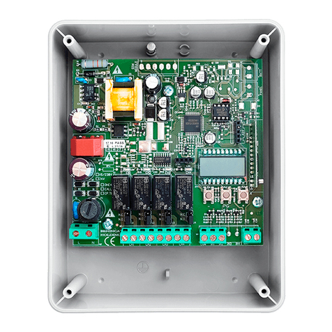
1) SPECIFICATIONS
- Four output, independent and freely configurable channels
- 433,92 MHz receiver configurable as rolling code HCS/advanced rolling code (ARC)/ fixed code.
- Programming through built-in LCD display
- Programming through ADVANTOUCH programmer and corresponding software for PC Windows (optional).
1.1) IN/OUT FUNCTIONS
Input No. Function Description
L-N Power supply Power supply 90-255 Vac 50/60 Hz
CH1 Channel 1
Output, channel 1. 250 Vac max 5A.
Normally Open (N.O.) Contact, switchable in Normally Closed (N.C.)
through jumper 1.
CH2 Channel 2 Output, channel 2. 250 Vac max 5A.
N.O. Contact, switchable in N.C. through jumper 2.
CH3 Channel 3 Output, channel 3. 250 Vac max 5A.
N.O. Contact switchable in N.C. through jumper 3.
CH4 Channel 4 Output, channel 4. 250 Vac max 5A.
N.O. Contact, switchable in N.C. through jumper 4.
COM-IN1-IN2 Input 1 and 2
Inputs configurable by means of the parameter and logic menu, they
can activate one of the channel CH1/CH2/CH3/CH4 in the same way of
a remote control.
ANT-SHIELD Antenna Antenna connection of the built-in radio module
(11-screen/12-signal).
ADV Connector
ADVANTOUCH
Input for ADVANTOUCH (C4 Cable).
The receiver memory can be managed through the ADVANTOUCH
software and the relevant programmer.
For further information, please refer to ADVANTOUCH instructions
Note:
The U6 memory can contain 512 rolling-code HCS or ARC, 433.92MHz, transmitters maximum. If necessary, it can
be replaced with item MEM2048 which can contain up to 2048 different codes.
2) ARC (ADVANCED ROLLING CODE)
The radio receiver ONE4.WB is compatible with the new ARC (Advanced Rolling Code) transmitters which, thanks
to 128-bit encryption ensure superior copy-security.
Storing new ARC transmitters is quite similar to that of normal rolling code transmitters with HCS coding, but be
aware that:
1) Transmitters of different encoding type cannot be stored in the same ONE.4WB.
2) The first transmitter stored in memory defines the type of transmitters to be used afterwards. For example if the
first transmitter is ARC it will not be possible to store in memory rolling code (HCS ) transmitters or fixed code ones
and vice versa.
3) If you want to change the type of transmitters it is necessary to proceed with a receiver reset (Menu Radio>Reset).
When the receiver is switched on or by pressing the buttons (+) and (-) simultaneously the screen shows the type
of transmitters in use according to the following diagram:
RC rolling code HCS
ARC advanced rolling code
Fix fixed code
- - - no transmitters in memory/ no encoding type set

10
3) PROGRAMMING
The programming of the various functions of the control unit is carried out by using the LCD display in the receiver
and presetting the desired values in the programming menus described hereunder.
1 - Press the <PG> key, the display shows the first Parameters Menu “PAR”.
2 - By using the keys <+> or <->, select the desired Menu (PAR>>LOG>>RADIO>>....).
3 - Press the <PG> key, the display shows the first function available on the Menu.
4 - By using the keys <+> or <->, select the function to be modified.
5 - Press the <PG> key, the currently preset value for the selected function is displayed.
6 - By using the <+> or <-> keys, select the value to be assigned to the function.
7 - Press the <PG> key, “PRG” is displayed which means the programming has been successful.
Note: You can return to the upper menu without making changes if you press the <+> and <-> keys simultaneously
in a Function Menu.
Press PG to select the desired value. OK is shown to confirm a successful programming.
After 60 sec wait, the receiver exits the programming mode and the display switches off.
Each single function, which is available in the control unit, is described in the following tables.
3.1) PARAMETER
MENU FUNCTION
MCH1
The operating mode of channel 1 is preset.
The descriptions of the single submenus are shown hereunder:
IMp Monostable. The relay activates for 1 sec when the corresponding key is pressed;
then the relay returns to its original status.
TG Bistable. When the associated key in the transmitter is pressed, the relay activates.
It remains in its new status until the key is pressed again.
time
Timed. The switching time of the relay can be set between 1 second and 10 minutes.
By using the <+> and <-> keys, select the desired time. The presettable values are:
from 1 to 10s with 1s steps
from 30s to 300s with 30s steps
from 300s to 600s with 60s steps.
cont The relay switches each time the corresponding key in the transmitter is pressed
and returns to its original status after its realise.
MCH2 Same operating modes preset for MCH1.
MCH3 Same operating modes preset for MCH1.
MCH4 Same operating modes preset for MCH1.
in1 Allows to associate to the input 1 one of the output channel, select a value among the following:
OFF-CH1-CH2-CH3-CH4 (default CH1)
In2 Allows to associate to the input 2 one of the output channel, select a value among the following:
OFF-CH1-CH2-CH3-CH4 (default CH2)
3.2) LOGICS
MENU FUNCTION
safe
With this function enabled, channel 1 switches only if the corresponding key is pressed for
longer than 3 seconds.
This function is useful specially to control alarm installations or in cases when accidental acti-
vation is to be averted. The default function is preset on OFF.
In1
Allows to set the type of contact to be used for the input 1, select a value between N.O.
(default) N.C.
N.O.: normally open contact N.C.: normally close contact
In2
Allows to set the type of contact to be used for the input 2, select a value between N.O.
(default) N.C.
N.O.: normally open contact N.C.: normally close contact

11
3.3) RADIO
MENU FUNCTION
If selecting the menu Radio the screen shows “PSU”, it means that the memory has been protected by a Password using
the programmer ADVANTOUCH. Every operation on the receiver memory can be done only with the ADVANTOUCH.
Add
Menu to type in the transmitter codes in memory. The message FULL means that the receiver
memory is complete. The submenus are described hereunder:
ch1
The key is associated to channel 1. Press, within 5 sec, the transmitter key which
is to be associated to channel 1.
Synchronism control is activated (see Synchronism paragraph).
ch2
The key is associated to channel 2. Press, within 5 sec, the transmitter key which
is to be associated to channel 2.
Synchronism control is activated (see Synchronism paragraph).
ch3
The key is associated to channel 3. Press, within 5 sec, the transmitter key which
is to be associated to channel 3.
Synchronism control is activated (see Synchronism paragraph).
ch4
The key is associated to channel 4. Press, within 5 sec, the transmitter key which
is to be associated to channel 4.
Synchronism control is activated (see Synchronism paragraph).
SInc
The four keys of a four channel transmitter are automatically associated, each
one to the corresponding channel. (Key1:ch1, key2:ch2, key3:ch2 and key4:ch4).
Press, within 5 seconds, any key of a four channel transmitter.
Synchronism control is activated (see Synchronism paragraph).
FIX
The four keys of a four channel transmitter are automatically associated, each
one to the corresponding channel. (Key1:ch1, key2:ch2, key3:ch2 and key4:ch4).
Press, within 5 seconds, any key of a four channel transmitter.
Synchronism control is not activated (see Synchronism paragraph).
SER
Serialised remote controls are typed in.
Packages of factory serialised remote controls, i.e. transmitters with consecutive
codes. First of all press any key on the transmitter with lower serial code, then
any key on the transmitter with higher serial code. All transmitter codes which
are within these two codes will be automatically stored in memory. Associations
are automatically carried out (key1:ch1, key2:ch2, etc)
Synchronism control is activated (see Synchronism paragraph).
del
Menu to erase previously typed in transmitter codes from memory.
The single submenus are described hereunder:
code
The receiver is in a waiting mode, waiting for a memorized transmitter key to
be pressed.
The transmitter is erased from the receiver memory.
indh Remove a control unit code for which the position in memory is know, see fun-
ction Find>Code
recn
Remove a control unit code for which the position in memory is know, see fun-
ction Find>Code.
Unlike the function InDh which scrolls through all the positions of the memory, the
menu rEcn scrolls only through the positions occupied by a transmitter.
res
Clears completely the receiver memory deleting all the transmitters, their associations, the
encoding type settings and the parameters of the channels. It is necessary to confirm this
operation before to proceed.

12
find
Search Menu for transmitter codes stored in memory.
The single submenus are described hereunder:
code The receiver will wait to receive a code, press a button on the transmitter, if
present, see the location in memory.
n tx The number of transmitter codes stored in the receiver memory is displayed.
3.4) PASSWORD (pass)
It allows to type in an access protection code to the programming of the control unit.
A four-character alphanumeric code can be typed in by using the numbers from 0 to 9 and the letters A-B-C-D-E-F.
The default value is 0000 (four zeros) and shows the absence of a protection code.
While typing in the code, this operation can be cancelled at any moment by pressing keys + and – simultaneously.
Once the password is typed in, it is possible to act on the control unit by entering and exiting the programming
mode for around 10 minutes in order to allow adjustments and tests on functions.
By replacing the 0000 code with any other code, the protection of the control unit is enabled, thus preventing
the access to any other menu. If a protection code is to be typed in, proceed as follows:
- select the Code menu and press OK.
- the code 0000 is shown, also in the case a protection code has been previously typed in.
- the value of the flashing character can be changed with keys + and -.
- press OK to confirm the flashing character, then confirm the following one.
- after typing in the 4 characters, a confirmation message “CONF” appears.
- after a few seconds, the code 0000 appears again
- the previously stored protection code must be reconfirmed in order to avoid any accidental typing in.
If the code corresponds to the previous one, a confirmation message “OK” appears.
The control unit automatically exits the programming phase. To gain access to the Menus again, the stored
protection code must be typed in.
IMPORTANT: TAKE NOTE of the protection code and KEEP IT IN A SAFE PLACE for future maintenance operations.
To remove a code from a protected control unit it is necessary to enter into programming with the pas-
sword and bring the code back to the 0000 default value.
IF YOU LOOSE THE CODE, PLEASE CONTACT THE AUTHORISED SERVICE CENTER FOR THE TOTAL
RESET OF THE CONTROL UNIT.
4) SYNCHRONISM
According to the typing in mode, the synchronism control may be activated or deactivated.
Transmitters with activated synchronism control
This is the default mode which allows synchronism between transmitter and receiver, thus ensuring the safety offered
by the rolling-code system/Advanced Rolling Code.
Transmitters with deactivated synchronism control
In this mode, the synchronism function is disabled and the transmitter code can be copied. Hence, by using the
ADVANTOUCH system, a virtually infinite number of transmitter codes identical to the original can be created.

33
Dichiarazione di Conformità UE (DoC)
Nome del produttore: Automatismi Benincà SpA
Indirizzo: Via Capitello, 45 - 36066 Sandrigo (VI) - Italia
Telefono: +39 0444 751030
Persona autorizzata a costruire la documentazione tecnica:
Automatismi Benincà SpA
Tipo di prodotto: Radioricevitore con frequenza 433,92MHz
Modello/Tipo: ONE4
Accessori: N/A
Il sottoscritto Luigi Benincà, in qualità di Responsabile Le-
gale, dichiara sotto la propria responsabilità che il prodotto
sopraindicato risulta conforme alle disposizioni imposte dalle
seguenti direttive:
Direttiva 2014/30/UE del Parlamento europeo e del Consiglio,
del 26 febbraio 2014, concernente l’armonizzazione delle legi-
slazioni degli Stati membri relative alla compatibilità elettro-
magnetica (EMCD), secondo le seguenti norme armonizzate:
EN 61000-6-2:2005, EN 61000-6-3:2007.
Direttiva 2014/35/EU DEL PARLAMENTO EUROPEO E
DEL CONSIGLIO del 26 febbraio 2014 concernente l’ar-
monizzazione delle legislazioni degli Stati membri relative
alla messa a disposizione sul mercato del materiale elettrico
destinato ad essere adoperato entro taluni limiti di tensione
(LVD), secondo le seguenti norme armonizzate:
EN 60335-1:2012 + A11:2014; EN 60335-2-103:2015.
Direttiva 2011/65/UE del Parlamento europeo e del Consiglio,
dell’ 8 giugno 2011, sulla restrizione dell’uso di determinate
sostanze pericolose nelle apparecchiature elettriche ed elet-
troniche (RoHS), secondo le seguenti norme armonizzate:
EN 50581:2012
Direttiva 1999/5/CE del Parlamento europeo e del Consiglio,
del 9 marzo 1999, riguardante le apparecchiature radio e le
apparecchiature terminali di telecomunicazione e il reciproco
riconoscimento della loro conformità (R&TTE), secondo le
seguenti norme armonizzate:
ETSI EN 301 489-3 V1.4.1 (2002) + ETSI EN 301 489-1
V1.4.1 (2002) + ETSI EN 300 220-3 V1.1.1 (2000) + EN
60950-1 (2001)
Benincà Luigi, Responsabile legale.
Sandrigo, 11/10/2016.
Il Certificato di Conformità di questo documento corrisponde
all'ultima revisione disponibile al momento della stampa e
può risultare differente per esigenze editoriali dall'originale
disponibile presso il produttore.
Il Certificato di Conformità più completo e recente è disponi-
bile consultando il sito: www.beninca.com oppure può essere
richiesto presso:
Automatismi Benincà S.p.A - Sandrigo VI - Italy.
UE Declaration of Conformity (DoC)
Manufacturer's name: Automatismi Benincà SpA
Address: Via Capitello, 45 - 36066 Sandrigo (VI) - Italia
Telephone: +39 0444 751030
Person authorised to draft the technical documentation:
Automatismi Benincà SpA
Product type: 433,92MHz frequency radioreceiver
Model/type: ONE4
Accessories: N/A
The undersigned Luigi Benincà, as the Legal Officer, declares
under his liability that the aforementioned product complies
with the provisions established by the following directives:
Directive 2014/30/UE OF THE EUROPEAN PARLIA-
MENT AND OF THE COUNCIL of 26 February 2014, on
the harmonisation of the laws of Member States relating to
electromagnetic compatibility, according to the following
harmonised regulations:
EN 61000-6-2:2005, EN 61000-6-3:2007 + A1:2011.
Directive 2014/35/UE OF THE EUROPEAN PARLIA-
MENT AND OF THE COUNCIL of 26 February 2014, on
the harmonisation of the laws of Member States relating to
electrical equipment designed for use with certain voltage
limits, according to the following harmonised regulations:
EN 60335-1:2012 + A11:2014; EN 60335-2-103:2015.
Directive 2011/65/EU of the European Parliament and
Council, dated 8 June 2011, on the restricted use of certain
hazardous substances in electrical and electronic devices
(RoHS), according to the following standards:
EN 50581:2012
Directive 1999/5/CE OF THE EUROPEAN PARLIAMENT
AND COUNCIL, 9 March 1999 in relation to radio equipment
and telecommunications terminals and the mutual recognition
of their conformity, per the following harmonised standards:
ETSI EN 301 489-3 V1.4.1 (2002) + ETSI EN 301 489-1
V1.4.1 (2002) + ETSI EN 300 220-3 V1.1.1 (2000) + EN
60950-1 (2001)
Benincà Luigi, Legal Officer.
Sandrigo, 11/10/2016.
The certificate of conformity in this document corresponds
to the last review available at the time of printing and could
differ for editorial requirements from the original available
from the manufacturer.
The most recent and complete certificate of conformity is
available consulting the site: www.beninca.com or can be
requested from:
Automatismi Benincà SpA - Sandrigo VI - ITALY.
AUTOMATISMI BENINCÀ SpA - Via Capitello, 45 - 36066 Sandrigo (VI) - Tel. 0444 751030 r.a. - Fax 0444 759728
Other manuals for ONE.4WB
1
Table of contents
Other Beninca Receiver manuals

Beninca
Beninca ONE.4WB User manual

Beninca
Beninca RR.4WBV User manual

Beninca
Beninca CALL User manual

Beninca
Beninca LO.R1-2 Series User manual

Beninca
Beninca ONE2 WI User manual

Beninca
Beninca SC.RF User manual

Beninca
Beninca RR.1WBV User manual

Beninca
Beninca LO.R4WCV User manual

Beninca
Beninca ONE2 WI User manual

Beninca
Beninca RR.4WBP User manual