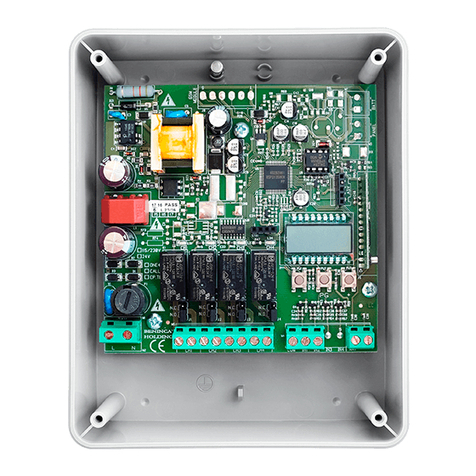
Beninca SC.RF User manual

L8542945
02/2013 rev 2
UNIONE NAZIONALE COSTRUTTORI
AUTOMATISMI PER CANCELLI, PORTE
SERRANDE ED AFFINI
SC.RF

2
67 mm
90 mm
26 mm
Fig.1

3
BZ
LD1
N.C. N.C.
W1/W2
CLOSE
BZ-12/24
CLOSE
DEFAULT
12/24
W2
W1
CH1 CH2 12/24V TSTANT
P
(+)(-)
ANT
SHIELD
Fig.2

4
SC.RF
DESCRIZIONE
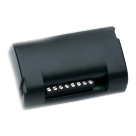
Radioricevitore bicanale con frequenza 868 MHz conforme alla
normativa EN 12978, da abbinare ai radiotrasmettitori per ante
mobili della serie RF/RF.SUN.
DIMENSIONI
In figura 1 sono rappresentate le dimensioni del contenitore
del radioricevitore. In dotazione viene fornito un biadesivo per
applicare il box all’interno dell’automazione o della centrale di
comando.
COLLEGAMENTI (Fig.4)
CH1* Uscita canale 1 replica la condizione del bordo sensibile
memorizzato sul canale 1 - contatto normalmente chiu-
so.
CH2* Uscita canale 2 replica la condizione del bordo sensibile
memorizzato sul canale 2 - contatto normalmente chiu-
so.
12/24 Ingresso alimentazione 12 o 24 Vac o Vdc, selezionabile
tramite il ponticello 12/24. Nel caso di alimentazione a
12/24 Vdc, rispettare le polarità indicate in Figura 2.
ANT Ingresso antenna. Per migliorare la ricezione può essere
necessario rimuovere il cavetto preinstallato ed utilizza-
re una antenna 868MHz.
TST Non utilizzare
* Le uscite CH1 e CH2 vanno collegate preferibilmente agli in-
gressi per bordo sensibile della centrale di comando. Gli ingres-
si in questo caso vanno configurati come se fossero collegati ad
bordo meccanico.
Normalmente gli ingressi per bordi sensibili prevedono, in caso
di intervento l’arresto immediato e l’inversione del movimento
per alcuni secondi.
In alternativa, nel caso non fossero disponibili ingressi per bordi
sensibili, è possibile collegare i canali CH1/CH2 ad altri ingressi
di sicurezza, come ad esempio ingressi per fotocellule o ingressi
per comandi di STOP.
Nel caso si renda necessario collegare i due canali ad un unico
ingresso nella centrale di comando, effettuare un collegamento
in serie delle due uscite.
JUMPER
SC.RF dispone di 2 ponticelli Jumper per le seguenti imposta-
zioni:
BZ: Abilita o disabilita il segnalatore acustico.
Jumper chiuso: segnalatore acustico attivo
Jumper aperto: buzzer non attivo
12/24
:Seleziona la tensione di alimentazione.
Jumper chiuso: 12 Vac/dc
Jumper aperto: 24 Vac/dco
MEMORIZZAZIONE DEL RADIOTRASMETTITORE
Per poter comunicare con il radiotrasmettitore RF/RF.SUN, è
necessario memorizzare il radiotrasmettitore stesso ed asse-
gnarlo ad uno dei due canali disponibili.
Per memorizzare sul canale 1, procedere come segue:
1) Premere 1 volta il pulsante P del RICEVITORE SC.RF
2) Il LED LD1 si accende ROSSO
3) Entro 20 secondi premere per circa 4 secondi il pulsante S1
del dispositivo RF/RF.SUN.
4) Il LED LD1 si spegne momentaneamente ed segnalatore acu-

5
stico avvisa dell’avvenuta memorizzazione.
5) Attendere lo spegnimento del LED LD1
Per memorizzare sul canale 2, procedere come segue:
1) Premere 1 volta il pulsante P del RICEVITORE SC.RF
2) Il LED LD1 si accende ROSSO.
3) Ripremere il pulsante P
4) Il LED LD1 commuta al colore VERDE.
5) Entro 20 secondi premere per circa 4 secondi il pulsante S1
del dispositivo RF/RF.SUN.
6) Il LED LD1 si spegne momentaneamente ed segnalatore acu-
stico avvisa dell’avvenuta memorizzazione.
7) Attendere lo spegnimento del LED LD1.
IMPORTANTE!
E’ possibile memorizzare fino a 4 diversi dispositivi su ogni
singolo canale, il completamento della memoria disponibile
viene segnalato da 3 lampeggi del LED.
RESET DEL RICEVITORE SC.RF
Nel caso si desideri cancellare tutte le impostazioni e riportare
SC.RF alle condizioni di fabbrica:
- Togliere alimentazione alla ricevente.
- Premere e mantenere premuto il pulsante P.
- Ridare alimentazione mantenendo premuto il pulsante P sulla
ricevente.
- Il LED inizia a lampeggiare rosso/verde, dopo circa 5 secondi
passa al colore arancione, rilasciare il pulsante P e attendere lo
spegnimento del LED.
DIAGNOSTICA
Nel normale funzionamento il colore del LED segnala lo stato
dei due canali:
Led rosso - canale 1 attivo
Led verde - canale 2 attivo
Il segnalatore acustico (se abilitato) seganala i seguenti eventi:
- accensione dispositivo
- uscita da menu configurazione
- batteria scarica del dispositivo mobile (periodicamente si ac-
cende anche il led sul dispositivo mobile ).
SMALTIMENTO
Qualora il prodotto venga posto fuori servizio, è necessario se-
guire le disposizioni legislative in vigore al momento per quanto
riguarda lo smaltimento differenziato ed il riciclaggio dei vari
componenti (metalli, plastiche, cavi elettrici, ecc.); è consiglia-
bile contattare il vostro installatore o una ditta specializzata ed
abilitata allo scopo.
Caratteristiche Tecniche SC.RF
Frequenza 868 MHz
Alimentazione 12/24 Vac/Vdc
Grado di protezione IP 30
Portata senza antenna 30m
con antenna 100m
Canali 2 (4 dispositivi max per
ogni canale)
Contatto relè 1A/24 Vdc
Temp. funzionamento -20/+50°C
Consumo a riposo 10 mA
Consumo con 1 canale attivo 42 mA
Consumo con 2 canali attivi 66 mA

6
SC.RF
DESCRIPTION
Two-channel radio receiver, with 868 MHz frequency, pursuant
to the regulation EN 12978, to be matched to radio transmitters
of the RF/RF SUN series for movable clsoures.
OVERALL DIMENSIONS
The overall dimensions of the radio-receiver box are shown in
Figure 1. A bi-adhesive strip is supplied to apply the box inside
the automation system or the control system.
WIRE CONNECTIONS (Fig. 4)
CH1* Output, channel 1 replies the status of the sensitive sa-
fety edge memorised on channel 1 – normally closed
contact.
CH2* Output, channel 2 replies the status of the sensitive sa-
fety edge memorised on channel 2 – normally closed
contact.
12/24 Input, 12 or 24 VAC or VDC power supply. It can be
selected through a 12/24 jumper. In case of 12/24 VDC
power supply, keep to poles shown in Figure 2.
ANT Input, antenna. For a better reception, it might be ne-
cessary to remove the pre-installed cable and use a
868MHz antenna.
TST Not use
* CH1 and CH2 outputs are mainly connected to inputs for the
sensitive edge of the control unit. In this case, inputs
should be preset as if they were connected to a safety
edge of the mechanical type.
The inputs for sensitive safety edges usually provide that, in the
event they are activated, the system is immediately stopped and
the movement is reversed for some seconds.
As an alternative, should no inputs be provided for sensitive
safety edges, channels CH1/CH2 can be connected to other
safety inputs, namely inputs for photocells or inputs for STOP
control signals.
If two channels must be connected to one single input in the
control system, the two outputs should be connected in series.
JUMPER
SC.RF is equipped with 2 jumpers for the following pre-set-
tings:
BZ: The acoustic signal is enabled or disabled.
Closed jumper: activated sound indicator
Open jumper: not activated buzzer
12/24:
Power voltage is selected.
Closed jumper: 12 VAC/DC
Open jumper: 24 VAC/VDC
HOW TO STORE THE RADIO TRANSMITTER IN MEMORY
In order to be able to communicate with the RF/RF.SUN radio-
transmitter, the transmitter code must be memorised and assi-
gned to either channels available.
In order to memorise the code on channel 1, proceed as fol-
lows:
1) Press push-button P of the SC-RF RECEIVER once
2) The LED LD1 switches on with RED light
3) Within 30 seconds, press push-button S1 of the RF/RF.SUN
device for around 4 seconds.
4) The LED LD1 switches off temporarily and a buzz indicates
that the storage in memory has been successful.
5) Await that the LED LD1 switches off

7
In order to memorise the code on channel 2, proceed as follows:
1) Press push-button P of the SC-RF RECEIVER once
2) The LED LD1 switches on with RED light.
3) Press push-button P once again
4) The LED LD1 switches to GREEN light.
5) Within 30 seconds, press push-button S1 of the RF/RF.SUN
device for around 4 seconds.
6) The LED LD1 switches off temporarily and a buzz indicates
that the storage in memory has been successful.
7) Await that the LED LD1 switches off.
IMPORTANT!
Up to 4 different devices can be memorised on each sin-
gle channel. When the memory available is full, the LED will
flash three times.
HOW TO RESET THE SC.RF RECEIVER
If all presetting must be erased and the SC.RF receiver must be
restored to factory pre-setting:
- Cut power supply off.
- Press push-button P and keep it pressed.
- Power the system again, keeping the push-button P pressed
on the receiver.
- The LED starts flashing with red/green light. After around 5
seconds, when the light turns orange, release the button P and
wait that the LED switches off.
DIAGNOSTICS
During normal operation, the colour of the LED indicates the
status of the two channels:
Red LED – channel 1 activated
Green LED – channel 2 activated
The Buzzer (if enabled) indicates the following events:
- device switching on
- exit from configuration menu
- down battery of the mobile device (also the LED on the mobile
device switches on periodically).
DISPOSAL
When the product is out of order, it must be disposed accor-
ding to regulations in force on waste disposal and recycling of
the various components (metal, plastics, electrical wires, etc.).
For this purpose, it is advisable to contact your installer or a
specialised company.
Specification SC.RF
Frequency 868 MHz
Power supply 12/24 Vac/Vdc
Protection level IP 30
Range Without antenna - 30m
With antenna - 100m
Channels 2 (4 devices max for each
channel)
Relay contact 1A/24 Vdc
Operating time -20/+50°C
Consumption at rest 10 mA
Consumption with 1
channel 42 mA
Consump. 2 channels
activated 66 mA

8
SC.RF
BESCHREIBUNG
2-Kanal-Funkempfänger mit Frequenz 868 MHz, entspricht der
Norm EN 12978 und kann mit Sendegeräten für mobile Torflü-
gel der Serie RF/RF.SUN verwendet werden.
MAßE
In der Abbildung 1 sind die Maße des Behälters des Funkemp-
fängers angegeben. Mitgeliefert wird ein doppelseitiges Klebe-
band, das im Inneren der Schachtel der Automatik oder der der
Steuereinheit angebracht werden muss.
ANSCHLÜSSE (Abb.4)
CH1* Ausgang Kanal 1 wiederholt die Bedingung der emp-
findlichen Schaltleiste, die auf Kanal 1 gespeichert ist
– Ruhekontakt.
CH2* Ausgang Kanal 2 wiederholt die Bedingung der emp-
findlichen Schaltleiste, die auf Kanal 2 gespeichert ist
– Ruhekontakt.
12/24 Eingang Stromversorgung 12 oder 24 Vac oder Vdc,
anwählbar über Brücke 12/24. Falls es sich um eine
Stromversorgung zu 12/24 Vdc handelt, ist die Polarität
laut Abbildung 2 zu beachten.
ANT Eingang Antenne. Um den Empfang zu verbessern
könnte es nötig sein, das vorinstallierte Kabel zu entfer-
nen und eine Antenne zu 868 MHz zu verwenden.
TST Nicht verwendet.
* Die Ausgänge CH1 und CH2 sollten vorzugsweise an die Ein-
gänge der empfindlichen Schaltleiste der Steuerzentrale verbun-
den werden. Die Eingänge werden in diesem Fall konfiguriert,
als wären sie an die mechanische Leiste angeschlossen.
Bei den Eingängen für die empfindliche Schaltleiste erfolgt in
der Regel einige Sekunden lang ein sofortiges Anhalten und
Umkehren der Bewegung, wenn diese einschalten.
Wenn keine Eingänge für empfindliche Schaltleisten zur Verfü-
gung stehen sollten, können, die Kanäle CH1/CH2 an andere
Sicherheitseingänge geschlossen werden, wie z.B. Eingänge für
Fotozellen oder Eingänge für STOPP-Befehle.
Sollten zwei Kanäle an einen einzigen Eingang der Steuerzentra-
le geschlossen werden müssen, die beiden Ausgänge in Reihe
schalten.
JUMPER
SC.RF verfügt über 2 Jumper Brücken, die folgenden Einstel-
lungen dienen:
BZ: Aktiviert oder deaktiviert das akustische Signal
Jumper geschlossen: akustisches Signal aktiv
Jumper geöffnet: Summer nicht aktiv.
12/24:
Wählt die Speisespannung
Jumper geschlossen: 12 Vac/dc
Jumper geöffnet: 24 Vac/dco
SENDEGERÄT SPEICHERN
Um mit dem Sendegerät RF/RF.SUN kommunizieren zu kön-
nen, muss dasselbe Sendegerät gespeichert und einem der
beiden Kanäle zugeteilt werden.
Um es auf Kanal 1 zu speichern, folgendermaßen vorgehen:
1) Taste P der EMPFÄNGERS SC.RF einmal drücken
2) Die LED LD1 leuchtet ROT auf
3) Die Taste S1 der Vorrichtung RF/RF.SUN innerhalb von 20
Sekunden circa 4 Sekunden lang drücken
4) Die LED LD1 erlischt vorübergehend und das akustische Sig-
nal meldet die erfolgte Speicherung

9
5) Abwarten, bis die LED LD1 erlischt
Um es auf Kanal 2 zu speichern, folgendermaßen vorgehen:
1) Taste P des EMPFÄNGERS SC.RF einmal drücken
2) Die LED LD1 leuchtet ROT auf
3) Taste P nochmals drücken
4) Die LED LD1 wechselt die Farbe und leuchtet GRÜN auf
5) Die Taste S1 der Vorrichtung RF/RF.SUN innerhalb von 20
Sekunden circa 4 Sekunden lang drücken
6) Die LED LD1 erlischt vorübergehend und das akustische Sig-
nal meldet die erfolgte Speicherung
7) Abwarten, bis die LED LD1 erlischt
WICHTIG! Es können bis zu 4 verschiedene Vorrichtungen
auf jeden Kanal gespeichert werden. Wenn der Speicher
voll ist, blinkt die LED dreimal.
RESET EMPFÄNGER SC.RF
Falls alle Einstellungen gelöscht werden sollen, um die ur-
sprünglichen Einstellungen wieder herzustellen, folgenderma-
ßen vorgehen:
- Stromversorgung vom Empfänger abtrennen.
- Die Taste P drücken und gedrückt halten.
- Das Gerät wieder mit Strom versorgen und dabei die Taste P
gedrückt halten.
- Die LED beginnt rot/grün zu blinken. Nach ca. 5 Sekunden
zeigt die Led ein orangefarbenes Licht. Die Taste P loslassen
und abwarten bis die LED erlischt.
DIAGNOSTIK
Bei normalem Betrieb meldet die LED den Status der beiden
Kanäle:
Rote LED – Kanal 1 aktiv
Grüne LED – Kanal 2 aktiv
Das akustische Signal (wenn aktiviert) meldet folgende Ereig-
nisse:
- Einschalten der Vorrichtung
- Beenden des Konfigurationsmenüs
- Batterie der mobilen Vorrichtung ist leer (periodisch leuchtet
auch die Led an der mobilen Vorrichtung auf).
ENTSORGUNG
Falls das Produkt entsorgt werden soll, halten Sie sich bitte an
die für Sondermüll und Wiederverwertung der verschiedenen
Komponenten (Metall, Kunststoff, Stromkabel etc.) geltenden
Gesetzesvorschriften; wenden Sie sich hierfür an Ihren Installa-
teur oder an eine zugelassene Entsorgungsstelle.
Technische Eigenschaften SC.RF
Frequenz 868 MHz
Speisung 12/24 Vac/Vdc
Schutzklasse IP 30
Tragweite ohne Antenne 30m
mit Antenne 100m
Kanäle 2 (4 Vorrichtungen max.
pro Kanal)
Relaiskontakt 1A/24 Vdc
Betriebstemperatur -20/+50°C
Verbrauch im Ruhezustand 10 mA
Verbrauch mit 1 aktiven Kanal 42 mA
Verbrauch mit 2 aktiven Kanälen 66 mA

10
SC.RF
DESCRIPTION
Radio récepteur bicanal avec fréquence 868 MHz en conformité
avec la normative EN 12978, à joindre aux émetteurs radioélec-
triques pour vantaux mobiles de la série RF/RF.SUN.
DIMENSIONS
La figure 1 illustre les dimensions du coffret’ qui contient l’émet-
teur radioélectrique. Pour appliquer le coffret à l’intérieur de la
centrale ou de l’automatisme un bi- adhésif est fourni.
BRANCHEMENTS (Fig.4)
CH1* Sortie canal 1 réplique la condition de la barre palpeuse
mémorisée sur le canal 1 – contact normalement fer-
mé.
CH2* Sortie canal 2 réplique la condition de la barre palpeuse
mémorisée sur le canal 2 - contact normalement fermé.
12/24 Entrée alimentation 12 ou 24 Vac ou Vdc, sélectionnable
à l’aide du pontet 12/24. En cas d’alimentation 12/24
Vdc, respecter les polarités indiquées dans la Figure 2.
ANT Entrée antenne. A’ fin d’améliorer la réception il pourrait
s’avérer nécessaire d’ôter le câbleau préinstallé et utili-
ser une antenne 868MHz.
TST Pàs Utiliser.
* Les sorties CH1 et CH2 doivent être branchées de préférence
aux entrées pour barre palpeuse de la centrale de commande.
Dans ce cas, les entrées doivent être configurées comme si
elles étaient branchées à la barre palpeuse mécanique.
En principe les entrées pour barres palpeuses prévoient, en
cas d’intervention, l’arrêt immédiat et l’inversion du mouvement
pendant quelques secondes.
Autrement, ayant des entrées disponibles pour barres pal-
peuses, il est possible de brancher les canaux CH1/CH2 à
d’autres entrées de sécurité, comme par exemple les entrées
pour photocellules ou les entrées pour commande de STOP.
En cas de nécessité brancher les deux canaux à une seule en-
trée dans la centrale de commande, effectuer un branchement
en série des deux sorties.
CAVALIER
SC.RF dispose de 2 pontets cavaliers pour les réglages ci de
suite:
BZ: Active ou désactive l’ avertisseur acoustique.
Cavalier fermé: avertisseur acoustique actif
Cavalier ouvert: avertisseur non actif
12/24:
Sélectionne la tension d’alimentation.
Cavalier fermé: 12 Vac/dc
Cavalier ouvert: 24 Vac/dco
MEMORISATION DE L’EMETTEUR RADIO ELECTRIQUE
Pour communiquer avec l’émetteur radioélectrique RF/RF.SUN,
il faut mémoriser l’émetteur radio électrique même et l’affecter à
un des deux canaux disponibles.
Pour mémoriser sur le canal 1, procéder comme il suit:
1) Appuyer 1 fois sur la touche P du RECEPTEUR SC.RF
2) La LED LD1 s’allume et devient ROUGE
3) Dans l’espace de 20 secondes appuyer pendant environ 4
secondes sur la touche S1 du dispositif RF/RF.SUN.
4) La LED LD1 s’éteint momentanément et l’avertisseur acous-
tique avertit que la mémorisation a eu lieu.
5) Attendre que la LED LD1 s’éteigne
Pour mémoriser sur le canal 1, procéder comme il suit:
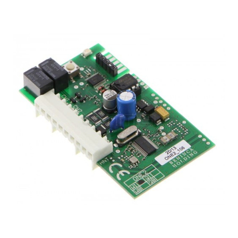
11
1) Appuyer 1 fois sur la touche P du RECEPTEUR SC.RF
2) La LED LD1 s’allume et devient ROUGE.
3) Appuyer encore sur la touche P.
4) La LED LD1 commute et devient VERTE.
5) Dans l’espace de 20 secondes appuyer pendant environ 4
secondes sur la touche S1 du dispositif RF/RF.SUN.
6) La LED LD1 s’éteint momentanément et le signaleur/avertis-
seur acoustique avertit que la mémorisation a eu lieu.
7) Atteindre que la LED LD1 s’éteint.
IMPORTANT!
Sur chaque canal il est possible de mémoriser jusqu’à 4 dis-
positifs différents, l’achèvement de la mémoire disponible
est signalé avec 3 clignotements de la LED.
REINITIALISATION DU RECEPTEUR SC.RF
Si l’on désire annuler tous les réglages et ramener SC.RF aux
conditions d’usine:
- Couper l’alimentation au récepteur.
- Appuyer sur la touche P et la garder appuyée.
- Rétablir l’alimentation en gardant appuyée la touche P sur le
récepteur.
- La LED commence à clignoter rouge / vert, après 5 secondes
environ elle devient orange, relâcher alors la touche P et attein-
dre que la LED s’éteigne.
DIAGNOSTIQUE
Lors du fonctionnement normal la couleur de la LED indique
l’état des deux canaux:
Led rouge - canal 1 actif
Led verte - canal 2 actif
avertisseur acoustique (si activé) indique les événements qui
suivent:
- allumage dispositif
- sortie du menu de configuration
- batterie du dispositif mobile à plat (périodiquement même la
Led sur le dispositif mobile s’allume).
TRI SELECTIF
Si le produit est mis hors service il faut suivre les termes de loi
en vigueur en ce moment en matière de tri sélectif et de recy-
clage des différentes composantes (métaux, plastiques, câbles
électriques, etc.); à ce fin il est conseillable de contacter son
installateur ou une société spécialisée.
Caractéristiques Techniques SC.RF
Fréquence 868 MHz
Alimentation 12/24 Vac/Vdc
Degrés de protection IP 30
Portée sans antenne 30m
avec antenne 100m
Canaux
2 (4 dispositifs maximum
pour chaque canal)
Contact relais 1A/24 Vdc
Temp. de fonctionnement -20/+50°C
Consommation à repos 10 mA
Consommation avec 1 canal actif
42 mA
Consommation avec 2 canaux actifs
66 mA

12
SC.RF
DESCRIPCIÓN
Radiorreceptor bicanal con frecuencia de 868 MHz conforme a
la norma EN 12978, a combinar con los radiotransmisores para
puertas móviles de la serie RF/RF.SUN.
MEDIDAS
En la Figura 1 se presentan las medidas del contenedor del ra-
diorreceptor. Se incluye un adhesivo de dos caras para aplicar
la caja dentro de la automatización o de la central de control.
CONEXIONES (Fig.4)
CH1* Salida canal 1 replica la condición del borde sensible
memorizado en el canal 1 - contacto normalmente ce-
rrado.
CH2* Salida canal 2 replica la condición del borde sensible
memorizado en el canal 2 - contacto normalmente ce-
rrado.
12/24 Entrada de la alimentación de 12 ó 24 Vac ó Vdc, selec-
cionable mediante el puente 12/24. En caso de alimen-
tación con 12/24 Vdc, cabe respetar las polaridades
indicadas en la Figura 2.
ANT Entrada de antena. Para mejorar la recepción puede ser
necesario quitar el cable instalado de antemano y utili-
zar una antena de 868MHz.
TST No utilizar.
* Las salidas CH1 y CH2 se tienen que conectar preferentemen-
te con las entradas para borde sensible de la central de control.
Las entradas en este caso se tienen que configurar como si es-
tuvieran conectadas con un borde mecánico.
Normalmente las entradas para bordes sensibles prevén, en
caso de actuación, la parada inmediata y la inversión del movi-
miento por unos segundos.
En alternativa, si no hubiera disponibles entradas para bordes
sensibles, es posible conectar los canales CH1/CH2 con otras
entradas de seguridad, como por ejemplo entradas para fotocé-
lulas o entradas para mandos de STOP.
Si fuese necesario conectar los dos canales con una única en-
trada en la central de control, efectúe una conexión en serie de
las dos salidas.
PUENTE
SC.RF dispone de 2 puentes Jumper para le siguientes confi-
guraciones:
BZ: Habilita o inhabilita el aviso acústico.
Jumper cerrado: aviso acústico activo
Jumper abierto: zumbador no activo
12/24:
Selecciona la tensión de alimentación.
Jumper cerrado: 12 Vac/dc
Jumper abierto: 24 Vac/dc
MEMORIZACIÓN DEL RADIOTRANSMISOR
Para poder comunicar con el radiotransmisor RF/RF.SUN, es
necesario memorizar el propio radiotransmisor y asignarlo a
uno de los dos canales disponibles.
Para memorizar en el canal 1, proceder como sigue:
1) Apretar 1 vez el botón P del RECEPTOR SC.RF
2) El LED LD1 se enciende de color rojo
3) Dentro de 20 segundos apretar, durante aproximadamente 4
segundos, el botón S1 del aparato RF/RF.SUN.
4) El LED LD1 se apaga momentáneamente y toca el aviso
acústico para indicar que la memorización ha sido efectuada.

13
5) Esperar que se apague el LED LD1
Para memorizar en el canal 2, proceder como sigue:
1) Apretar 1 vez el botón P del RECEPTOR SC.RF
2) El LED LD1 se enciende de color rojo.
3) Volver a apretar el botón P
4) El LED LD1 pasa al color verde.
5) Dentro de 20 segundos apretar, durante aproximadamente 4
segundos, el botón S1 del aparato RF/RF.SUN.
6) El LED LD1 se apaga momentáneamente y toca el aviso
acústico para indicar que la memorización ha sido efectuada.
7) esperar que se apague el LED LD1.
¡IMPORTANTE!
Se pueden memorizar hasta 4 distintos aparatos en cada
canal individual, el llenado de la memoria disponible lo indi-
can 3 parpadeos del LED.
RESET DEL RECEPTOR SC.RF
Si se desea borrar las configuraciones y poner de nuevo el
SC.RF a las condiciones de fábrica:
- Corte la alimentación para la receptora.
- Apriete y mantenga pulsado el botón P.
- Vuelva a dar corriente apretando el botón P en la receptora.
- El LED empieza a parpadear en los colores rojo/verde, al cabo
de unos 5 segundos pasa al color naranja, suelte el botón P y
espere que se apague el LED.
DIAGNÓSTICO
En el funcionamiento normal el color del LED indica el estado
de los dos canales:
LED rojo - canal 1 activo
LED verde - canal 2 activo
El aviso acústico (si habilitado) indica los siguientes eventos:
- encendido del aparato
- salida del menú de configuración
- batería descargada del aparato móvil (periódicamente se en-
ciende también el LED en el aparato móvil).
ELIMINACIÓN
Si se pone fuera de servicio el producto, entonces es necesario
ajustarse a las disposiciones legislativas vigentes en ese mo-
mento en cuanto a la eliminación selectiva y el reciclaje de los
varios componentes (metales, plástico, cables eléctricos, etc.);
se aconseja contactar con el propio instalador o con una em-
presa especializada y autorizada para dichas operaciones.
Características Técnicas SC.RF
Frecuencia 868 MHz
Alimentación 12/24 Vac/Vdc
Grado de protección IP 30
Alcance sin antena 30m
con antena 100m
Canales
2 (4 aparatos máx. para
cada canal)
Contacto relé 1A/24 Vdc
Temp. de funcionamiento -20/+50°C
Consumo en reposo 10 mA
Consumo con 1 canal activo 42 mA
Consumo con 2 canales activos 66 mA

14
SC.RF
OPIS
Radioodbiornik dwukanałowy o częstotliwości 868 MHz zgod-
ny z wymogami normy EN 12978, do użytku łącznie z radiona-
dajnikami do ruchomych bram serii RF/RF.SUN.
WYMIARY
Na rysunku 1 przedstawiono wymiary obudowy radioodbiorni-
ka. W skład opakowania wchodzi taśma obustronnie przylepna
służąca do umocowania pojemnika wewnątrz bramy lub cen-
tralki sterowniczej.
POŁĄCZENIA (Rys.4)
CH1* Wyjście kanału 1 powtarza stan zabezpieczenia kra-
wędziowego zapisany w kanale 1 – styk normalnie za-
mknięty.
CH2* Wyjście kanału 2 powtarza stan zabezpieczenia kra-
wędziowego zapisany w kanale 2 – styk normalnie za-
mknięty.
12/24 Wejście zasilania 12 lub 24 Vac albo Vdc, do zaznacze-
nia za pośrednictwem mostku 12/24. W przypadku za-
silania 12/24 Vdc, przestrzegać biegunowości podanej
na Rysunku 2.
ANT Wejście anteny. W celu polepszenia odbioru może oka-
zać się konieczne usunięcie wstępnie zainstalowanego
kabla i użycie anteny 868MHz.
TEST Nie stosować
* Wyjścia CH1 i CH2 powinny być podłączone możliwie do
wejść zabezpieczenia krawędziowego centralki sterowania. W
tym przypadku, wejścia powinny być skonfigurowane tak, jakby
były podłączone do zabezpieczenia mechanicznego.
Zwykle, wejścia zabezpieczenia krawędziowego przewidują, w
przypadku interwencji, natychmiastowe zatrzymanie i odwróce-
nie kierunku ruchu na kilka sekund.
Ewentualnie, jeżeli nie są dostępne wejścia zabezpieczenia
krawędziowego, można podłączyć kanały CH1/CH2 do innych
wejść bezpieczeństwa, jak na przykład do wejść fotokomórek
lub wejść poleceń STOP.
Jeżeli należy podłączyć obydwa kanały do jednego wejścia w
centralce sterowniczej, połączyć szeregowo obydwa wyjścia.
JUMPER
Radioodbiornik SC.RF dysponuje 2 mostkami Jumper do na-
stępujących ustawień:
BZ: Włącza lub wyłącza sygnalizator akustyczny.
Jumper zamknięty: sygnalizator akustyczny aktywny
Jumper otwarty: brzęczyk nieaktywny
12/24:
Wybiera napięcie zasilania.
Jumper zamknięty: 12 Vac/dc
Jumper otwarty: 24 Vac/dco
ZAPIS RADIONADAJNIKA
Aby można było wymieniać sygnały z radionadajnikiem RF/
RF.SUN, należy go wpisać do pamięci i przypisać do jednego z
dwóch, dostępnych kanałów.
Aby wpisać go do pamięci kanału 1, postępować jak poniżej:
1) Nacisnąć i raz przycisk P ODBIORNIKA SC.RF
2) Dioda LED LD1 zacznie świecić na CZERWONO
3) W ciągu 20 sekund należy nacisnąć przez około 4 sekundy
przycisk S1 urządzenia RF/RF.SUN.
4) Dioda LED LD1 wyłącza się chwilowo i sygnalizator akustycz-
ny informuje o wpisaniu do pamięci.

15
5) Poczekać na wyłączenie się diody LED LD1
Aby wpisać go do pamięci kanału 2, postępować jak poniżej:
1) Nacisnąć i raz przycisk P ODBIORNIKA SC.RF
2) Dioda LED LD1 zacznie świecić na CZERWONO
3) Ponownie nacisnąć przycisk P
4) Dioda LED LD1 zmienia kolor na ZIELONY.
5) W ciągu 20 sekund należy nacisnąć przez około 4 sekundy
przycisk S1 urządzenia RF/RF.SUN.
6) Dioda LED LD1 wyłącza się chwilowo i sygnalizator akustycz-
ny informuje o wpisaniu do pamięci.
7) Poczekać na wyłączenie się diody LED LD1
UWAGA WAŻNE!
Można zapisać do 4 różnych urządzeń na każdym kanale,
uzupełnienie dostępnej pamięci jest sygnalizowane przez 3
mignięcia diody LED.
RESET ODBIORNIKA SC.RF
Jeżeli chce się skasować wszystkie ustawienia i przywrócić od-
biornik SC.RF do stanu fabrycznego:
- Odłączyć dopływ zasilania do odbiornika.
- Nacisnąć i podtrzymać na wciśniętej pozycji przycisk P.
- Wznowić dopływ zasilania podtrzymując na wciśniętej pozycji
przycisk P na odbiorniku.
- Dioda LED zacznie migać na czerwono/zielono, po około 5
sekundach zmieni kolor na pomarańczowy, zwolnić przycisk P i
poczekać na wyłączenie się diody LED.
DIAGNOSTYKA
Podczas normalnego funkcjonowania, kolor diody LED sygnali-
zuje stan obydwu kanałów:
Dioda Led czerwona- kanał 1 aktywny
Dioda Led zielona- kanał 2 aktywny
Sygnalizator akustyczny (jeżeli aktywny) sygnalizuje następują-
ce zdarzenia:
- włączenie urządzenia
- wyjście z menu konfiguracji
- rozładowana bateria urządzenia ruchomego (okresowo pod-
świetla się również dioda na urządzeniu ruchomym).
ZŁOMOWANIE
Jeżeli produkt ma być wycofany z eksploatacji, należy prze-
strzegać obowiązujących rozporządzeń prawnych w zakresie
selektywnej zbiórki odpadów i recyklingu komponentów (meta-
lu, tworzywa, kabli elektrycznych, itp.); zaleca się skontaktowa-
nie z zaufanym instalatorem lub wyspecjalizowanym ośrodkiem
zajmującym się zbiórką odpadów.
Charakterystyka techniczna SC.RF
Częstotliwość 868 MHz
Zasilanie 12/24 Vac/Vdc
Stopień ochrony IP 30
Zasięg bez anteny 30m
z anteną 100m
Kanały 2 (max 4 urządzenia
na każdym kanale)
Styk przekaźnika 1A/24 Vdc
Temp. robocza -20/+50°C
Zużycie w pozycji spoczynku 10 mA
Zużycie przy 1 kanale aktywnym 42 mA
Zużyciu przy 2 kanałach aktywnych 66 mA

16
Dichiarazione CE di conformità
Fabbricante: Automatismi Benincà SpA.
Indirizzo: Via Capitello, 45 - 36066 Sandrigo (VI) - Italia
Dichiara che:
Il radiotrasmettitore/radioricevitore per bordi sensibili mobili
SC.RF.
è conforme alle seguenti disposizioni pertinenti:
Direttiva sulla compatibilità elettromagnetica:
89/336/CCE, 93/68/CEE
Direttiva sulla bassa tensione: 73/23/CEE, 93/68/CEE
ETSI EN 301 489-3 V1.4.1 (2002)
ETSI EN 301 489-1 V1.4.1 (2002)
ETSI EN 300 220-3 V1.1.1 (2000)
EN12978
EN 954-1 CAT2
EN 12453
Benincà Luigi, Responsabile legale.
Sandrigo, 07/07/2011.
EC Declaration of Compliance
Manufacturer: Automatismi Benincà SpA.
Address: Via Capitello, 45 - 36066 Sandrigo (VI) - Italy
This is to certify that:
The radio-transmitter/radio-receiver for movable sensitive safety
edges:
SC.RF.
is compliant with the following regulations:
Directive on the electromagnetic compatibility:
89/336/CCE, 93/68/CEE
Directive on low voltage:73/23/CEE, 93/68/CEE
ETSI EN 301 489-3 V1.4.1 (2002)
ETSI EN 301 489-1 V1.4.1 (2002)
ETSI EN 300 220-3 V1.1.1 (2000)
EN12978
EN 954-1 CAT2
EN 12453
Benincà Luigi, Legal Officer.
Sandrigo, 07/07/2011.

17
EG-Konformitätserklärung
Der Hersteller: Automatismi Benincà SpA.
Adresse: Via Capitello, 45 - 36066 Sandrigo (VI) - Italien
erklärt dass:
das Sendegerät/der Empfänger für mobile empfindliche
Schaltleisten
SC.RF.
den nachfolgenden Vorschriften entspricht:
Richtlinie über die elektromagnetische Verträglichkeit:
89/336/CCE, 93/68/CEE
Richtlinie über Niederspannung: 73/23/CEE, 93/68/CEE
ETSI EN 301 489-3 V1.4.1 (2002)
ETSI EN 301 489-1 V1.4.1 (2002)
ETSI EN 300 220-3 V1.1.1 (2000)
EN12978
EN 954-1 CAT2
EN 12453
Benincà Luigi, Rechtsvertreter
Sandrigo, 07/07/2011.
Déclaration CE de conformité
Producteur: Automatismi Benincà SpA.
Adresse: Via Capitello, 45 - 36066 Sandrigo (VI) - Italia
Déclare que:
le radio émetteur / radio récepteur pour barres palpeuse mobiles
SC.RF.
Est conforme aux suivants termes de loi pertinents:
Directive sur la compatibilité électromagnétique: 89/336/CCE,
93/68/CEE
Directive sur la basse tension: 73/23/CEE, 93/68/CEE
ETSI EN 301 489-3 V1.4.1 (2002)
ETSI EN 301 489-1 V1.4.1 (2002)
ETSI EN 300 220-3 V1.1.1 (2000)
EN12978
EN 954-1 CAT2
EN 12453
Benincà Luigi, Responsable légal
Sandrigo, 07/07/2011.

18
Declaración CE de conformidad
Fabricante:: Automatismi Benincà SpA.
Dirección: Via Capitello, 45 - 36066 Sandrigo (VI) - Italia
Declara que:
El radiotransmisor/radiorreceptor para bordes sensibles móviles
SC.RF.
es conforme a las siguientes disposiciones pertinentes:
Directiva sobre la compatibilidad electromagnética: 89/336/
CCE, 93/68/CEE
Directiva sobre la baja tensión: 73/23/CEE, 93/68/CEE
ETSI EN 301 489-3 V1.4.1 (2002)
ETSI EN 301 489-1 V1.4.1 (2002)
ETSI EN 300 220-3 V1.1.1 (2000)
EN12978
EN 954-1 CAT2
EN 12453
Benincà Luigi, Responsable legal.
Sandrigo, 07/07/2011.
Deklaracja zgodności CE
Producent: Automatismi Benincà SpA.
Adres Via Capitello, 45 - 36066 Sandrigo (VI) - Włochy
oświadcza, że:
Radionadajnik/radioodbiornik do zabezpieczeń krawędziowych
ruchomych przed przeszkodami
SC.RF.
spełnia wymagania następujących przepisów prawnych:
Dyrektywy w sprawie kompatybilności elektromagnetycznej:
89/336/CCE, 93/68/CEE
Dyrektywy niskiego napięcia: 73/23/CEE, 93/68/CEE
ETSI EN 301 489-3 V1.4.1 (2002)
ETSI EN 301 489-1 V1.4.1 (2002)
ETSI EN 300 220-3 V1.1.1 (2000)
EN12978
EN 954-1 CAT2
EN 12453
Benincà Luigi, Upoważniony przedstawiciel prawny.
Sandrigo, 07/07/2011.

19

AUTOMATISMI BENINCÀ SpA
Via Capitello, 45 - 36066 Sandrigo (VI) - Tel. 0444 751030 r.a. - Fax 0444 759728
Other manuals for SC.RF
1
Table of contents
Languages:
Other Beninca Receiver manuals

Beninca
Beninca LO.R1-2 Series User manual

Beninca
Beninca RR.1WBP User manual

Beninca
Beninca LO.R4WCV User manual

Beninca
Beninca RR.4WBV User manual

Beninca
Beninca ONE2 WI User manual

Beninca
Beninca ONE.4WB User manual

Beninca
Beninca CALL User manual

Beninca
Beninca ONE.4WB User manual

Beninca
Beninca RR.4WBP User manual

Beninca
Beninca SC.RF User manual
Popular Receiver manuals by other brands

Pioneer
Pioneer VSX-D511 - Audio/Visual Receiver operating instructions

Parallax
Parallax 28048 manual

Sony
Sony STRDG820 - STR AV Receiver operating instructions

BWI Eagle
BWI Eagle AIR-EAGLE SR 38AN/DP-5-0001-120VAC Product information bulletin

Philips
Philips Matchline FR970 Specifications

Yamaha
Yamaha NS-IW280CWH owner's manual