Bennett H35 Series User manual
Maintenance Manual
High Flow H35 Hydrogen Series
Dual Cabinet Configuration
155211 Rev. B, 12.20.2023
H35 Maintenance Manual i
This manual contains important information for the safe maintenance of this equipment. Read and
understand this manual before applying power. All service personnel should read this manual before
performing service activities.
The material included in this manual is accurate at the date of publication. Failure to follow these
instructions could result in bodily injury, damage to the equipment, or death.
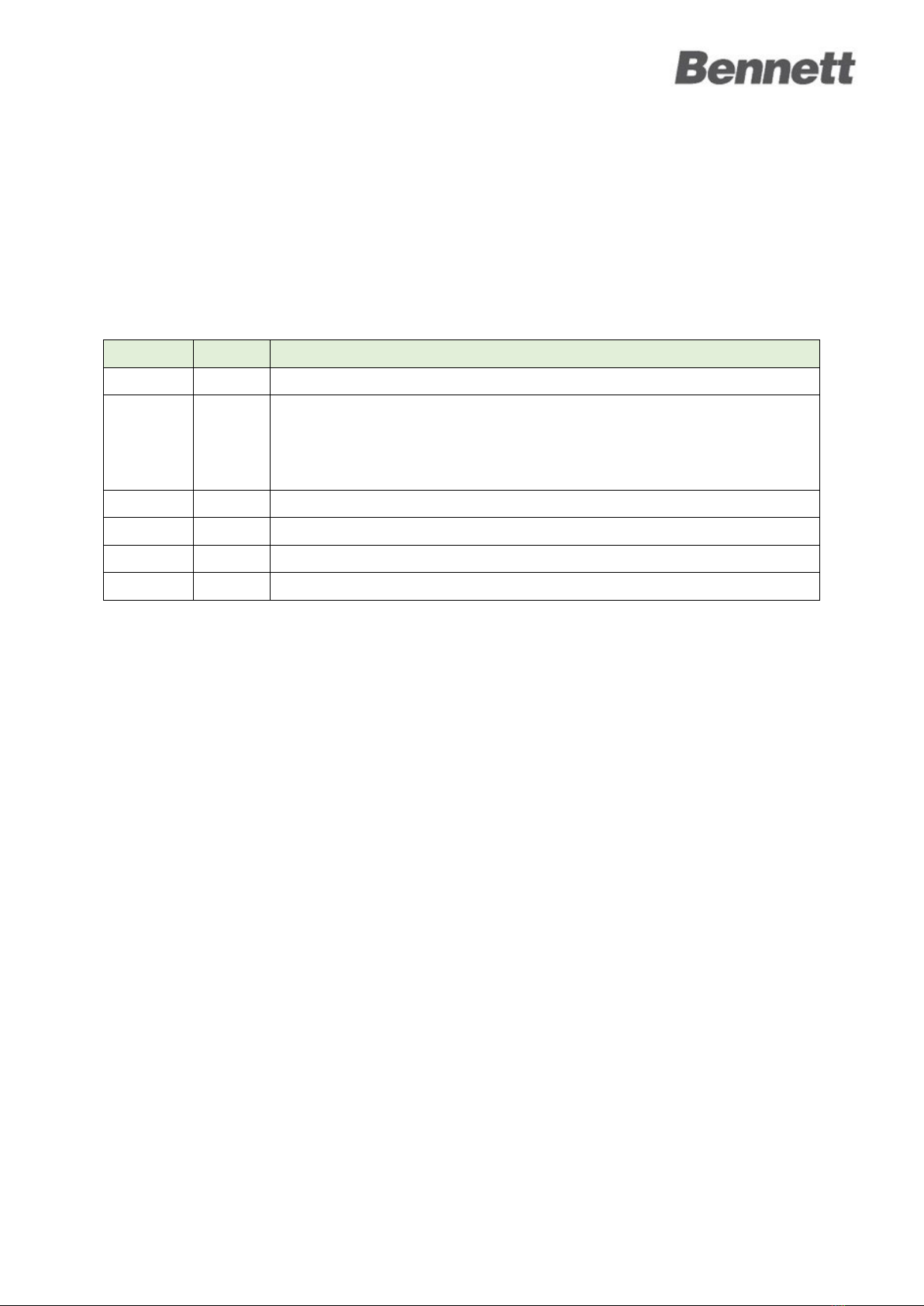
REV LEVEL
DATE
DESCRIPTION
A
11.22.23
Release
B 12.20.23
1. Safety instructions update.
2. Section and figure references repaired.
3. Fuse locations clarified.
4. Improved Meter zero offset procedure
5. Improved Gas Detector section

H35 Maintenance Manual ii
TABLE OF CONTENTS
1SAFETY INSTRUCTIONS ................................1
1.1 SAFETY MESSAGES.................................1
2INTRODUCTIONERROR! BOOKMARK NOT DEFINED.
3SERVICE, MAINTENANCE PROCEDURES ........4
3.1 PIPING &INSTRUMENTATION ..................4
3.1.1 LOCK-OUT PROCEDURES ...........................4
3.1.2 COMPONENT REMOVAL ...........................4
3.1.3 PIPING CONNECTIONS ..............................4
3.1.4 CHANGING FILTER ELEMENT......................5
3.2 FUELING CONTROL SYSTEM .....................5
3.2.1 LOCK-OUT PROCEDURES ...........................5
3.2.2 PLC PANEL FUSES ...................................5
3.3 819 ELECTRONICS,USER DISPLAYS,
CONTROLS ..........................................6
3.3.1 LOCK-OUT PROCEDURES ...........................6
3.3.2 819 POWER BOARD FUSE LOCATIONS ........6
4TROUBLESHOOTING GUIDE..........................7
4.1 PROGRAMMING AND COMMUNICATION.....7
4.1.1 PROGRAMMABLE LOGIC CONTROLLER (PLC)7
4.1.2 MANAGER’S KEYPAD WON’T ENTER
PROGRAMMING MODE ...........................7
4.1.3 DISPENSER COMMUNICATION ...................8
4.2 POWER AND DISPLAY.............................9
4.2.1 NO POWER ............................................9
4.2.2 THE DISPLAY AMOUNT AND POINT OF SALE
AMOUNT DON’T MATCH .........................9
4.2.3 BLANK DISPLAY .....................................10
4.2.4 DISPLAY SEGMENTS DISTORTED ...............10
4.2.5 DECIMAL PLACE IN WRONG POSITION ......10
4.2.6 NO DISPENSER BACKLIGHT......................10
4.3 HYDROGEN DISPENSING ....................... 11
4.3.1 DISPENSER HAS NO FLOW ...................... 11
4.3.2 SLOW DISPENSING FLOW ....................... 12
4.3.3 INACCURATE PRESSURE READING............. 12
4.3.4 DISPENSER LEAK ................................... 12
4.3.5 VALVE OR VALVES NOT OPENING ............ 12
4.3.6 DISPENSER STOPS PUMPING AFTER SEVERAL
SECONDS ............................................13
4.3.7 THE ELECTRONIC DISPENSER HEAD IS WET 13
5DISPENSER ERROR MESSAGES ...................14
5.1 ERROR CODES.................................... 14
6METER ZERO OFFSET PROCEDURE..............18
6.1 PASSCODES AND MENU SELECTION ......... 18
6.2 ZERO OFFSET CALIBRATION ................... 18
7GAS DETECTORS........................................20
7.1 RESPONSE CHECK AND CALIBRATION ....... 20
7.1.1 10.1 ZEROING AND SPAN CALIBRATION..... 20
8FILL TERMINATION REASON CODES ...........24
9APPENDIX A: MAINTENANCE LOG..............26
9.1 EXTERIOR ......................................... 26
9.2 ELECTRICAL ....................................... 27
9.3 PIPING AND INSTRUMENTATION ............. 28
9.4 OTHER EQUIPMENT............................. 30
9.5 DISPENSER TESTS................................ 31
10 APPENDIX B: FILTER SERVICE MANUAL ......32
Safety Instructions
H35 Maintenance Manual 1
1SAFETY INSTRUCTIONS
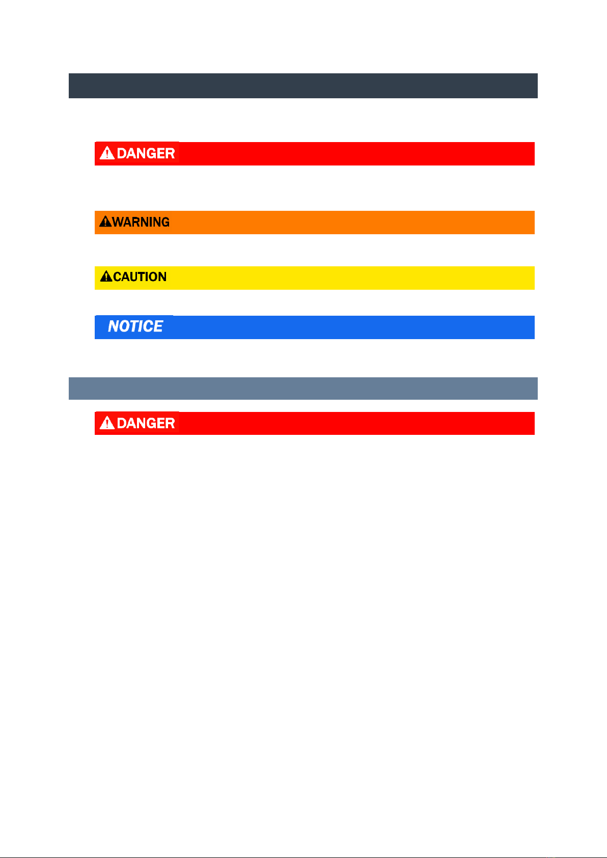
Please read and understand the following grouped safety messages that contain safety symbols and
safety words. They are defined as:
RED AND WHITE.IF YOU DO NOT FOLLOW THE INSTRUCTIONS, SEVERE INJURY OR DEATH
WILL OCCUR.
Orange and black. If you do not follow the instructions, severe injury or death can occur.
Yellow and Black. If you do not follow the instructions, damage can occur to the dispenser.
White italic NOTICE over blue. Indicates important information that should be observed.
1.1 SAFETY MESSAGES
1. DANGER: HYDROGEN IS FLAMMABLE. NO SMOKING OR OPEN FLAME
2. DANGER: ALWAYS PLACE A PHYSICAL BARRIER AROUND THE WORK AREA BEFORE
PERFORMING SERVICE OR MAINTENANCE.
3. DANGER: DISCONNECT ALL POWER TO THIS EQUIPMENT DURING INSTALLATION,
SERVICE, OR ANY MAINTENANCE.
4. DANGER: VERIFY PROPER VENTILATION IN THE DISPENSING AREA TO PREVENT
HYDROGEN BUILDUP.
5. DANGER: WEAR APPROPRIATE PERSONAL PROTECTIVE EQUIPMENT (PPE), INCLUDING
SAFETY GLASSES, GLOVES, AND ANTI-STATIC CLOTHING.
6. DANGER: BE FAMILIAR WITH EMERGENCY SHUTDOWN PROCEDURES.

Safety Instructions
H35 Maintenance Manual 2
1. WARNING: To prevent electric shock, keep the electrical parts of the dispenser dry.
2. WARNING: Electronic components are static sensitive. Use proper static precautions
(static straps) before working on the equipment.
3. WARNING: Only technicians who have been trained in operation and programming of
this dispenser should perform programming and maintenance.
1. CAUTION: Do not drill holes in fuel dispensers. Holes can cause failure of the electronic
equipment. The warranty will become void. Use only adhesive backed sign mounting
brackets.
Note: Dealing with hydrogen requires careful attention to safety procedures. If you are not trained
or experienced in handling hydrogen equipment, contact a qualified professional before attempting
any troubleshooting.
introduction
H35 Maintenance Manual 3
2INTRODUCTION
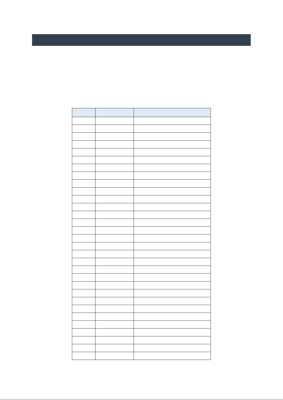
The following table lists the tags that identify each component in the dispenser. Please also refer to
these drawings. Some installations may vary:
•P6883, General Overview, H35 HF Main
Cabinet
•P6801, Piping and Instrumentation Diagram
(P&ID)
•P6921, General Overview, H35 HF Auxiliary
Cabinet
•Wire Diagram: P7148 or P7419
ITEM
TAG
DESCRIPTION
2
TE-100
Thermocouple
3
TE-101
Thermocouple
4
CG-100
Combustible Gas Detector
5
RO-100
Restrictive Orifice
6
SV-104 SV-103
Solenoid Valve
7
HV-100
Hand Valve
8
F-100
Filter
9
FCV-100
Flow Control Valve
10
HV-102
Hand Valve
11
SV-102
Solenoid Valve
12
HE-100
Heat Exchanger
13
RO-102
Restrictive Orifice
14
TT-100
Temperature Transmitter
15
M-100
Meter
16
PT-100
Pressure Transmitter
17
SVFV-100
Solenoid Valve
18
PSV-120
Pressure Safety Valve
19
CV-101
Check Valve
20
AOV-101
Air Operated Valve
21
TT-101
Temperature Transmitter
22
PT-101
Pressure Transmitter
23
CV-100
Check Valve
24
PCV-100
Pressure Control Valve
25
SV-200
Solenoid Valve
26
PSV-220
Pressure Safety Valve
27
TT-201
Thermocouple
28
PT-201
Pressure Transmitter
29
PT-104
Pressure Transmitter
30
CV-200
Check Valve
31
HV-103
Hand Valve
32
CG-200
Combustible Gas Detector

Service, Maintenance Procedures
H35 Maintenance Manual 4
3SERVICE, MAINTENANCE PROCEDURES
3.1 PIPING & INSTRUMENTATION
3.1.1 LOCK-OUT PROCEDURES
The following procedures must be performed before proceeding with any service or maintenance
work on the piping and instrumentation system.
•Isolate the dispenser from sources of pressure. Close the HV-100 Hydrogen Supply Shutoff
valve.
•Completely vent hydrogen out of the system. The maintenance software tool can be used to
manually toggle valves as required to open all portions of the system to the vent outlet.
•Shut OFF the power switch on the 819 Power Board.
•Shut OFF the breaker to isolate the dispenser from AC power.
•During any maintenance: Lock out the dispenser per the regulations of the site.
3.1.2 COMPONENT REMOVAL
Components are mounted to the dispenser frame and can be taken out of the unit by removing the
threaded fasteners holding them in place.
Note: The system must be fully depressurized before removing any component.
3.1.3 PIPING CONNECTIONS
3.1.3.1 CONE & THREAD (C&T)
The primary connection type on pressurized hydrogen lines is C&T. Tubes are fabricated with
tapered ends (cones) which provide a hard seal against a mating cone in the fitting or component.
The connection is maintained with a threaded connection torqued according to size.
When re-assembling medium pressure connections, apply a thread lubricant approved for use in
hydrogen piping systems. Torque fittings to the specifications listed below.
Fitting Size (Tube OD)
Torque Specification
ft-lbs
Nm
3/8”
30
41
9/16”
55
75
3/4"
75
102
Note: The system must be fully depressurized before removing any component.

Service, Maintenance Procedures
H35 Maintenance Manual 5
3.1.3.2 LOK TUBING & FITTINGS
LOK tubing and fittings connect parts of the system with lower pressure requirements (such as vent
and coolant lines). These connections are a tapered ferrule, permanently attached to the end of a
tube that seals against a mating surface inside the fitting or component.
•Before removal, draw a line across both nuts to mark the tightened position. When re-
installing, ensure they end in the same position.
•LOK Connections do not require the use of thread lube.
3.1.4 CHANGING FILTER ELEMENT
The filter element must be replaced as part of preventative maintenance on the dispenser.
•To change the filter, see the filter service manual in Appendix B.
•Filter housing torque: 30 ft-lbs (40 Nm).
3.2 FUELING CONTROL SYSTEM
3.2.1 LOCK-OUT PROCEDURES
The following procedures must be performed before proceeding with any service or maintenance
work on any electronics.
•Isolate the dispenser from sources of pressure. Close the HV-100 Hydrogen Supply Shutoff
valve.
•Completely vent hydrogen out of the system. The maintenance software tool can be used to
manually toggle valves as required to open all portions of the system to the vent outlet.
•Shut OFF the power switch on the 819 Power Board.
•Shut OFF the breaker to isolate the dispenser from AC power.
•During any maintenance: Lock out the dispenser per the regulations of the site.
3.2.2 PLC PANEL FUSES
For information on the PLC fuse locations and size see the Wire Diagram.
Service, Maintenance Procedures
H35 Maintenance Manual 6
3.3 819 ELECTRONICS, USER DISPLAYS, CONTROLS
3.3.1 LOCK-OUT PROCEDURES
The following procedures must be performed before proceeding with any service or maintenance
work on any electronics.
•Isolate the dispenser from sources of pressure. Close the HV-100 Hydrogen Supply Shutoff
valve.
•Completely vent hydrogen out of the system. The maintenance software tool can be used to
manually toggle valves as required to open all portions of the system to the vent outlet.
•Shut OFF the power switch on the 819 Power Board.
•Shut OFF the breaker to isolate the dispenser from AC power.
•During any maintenance: Lock out the dispenser per the regulations of the site.
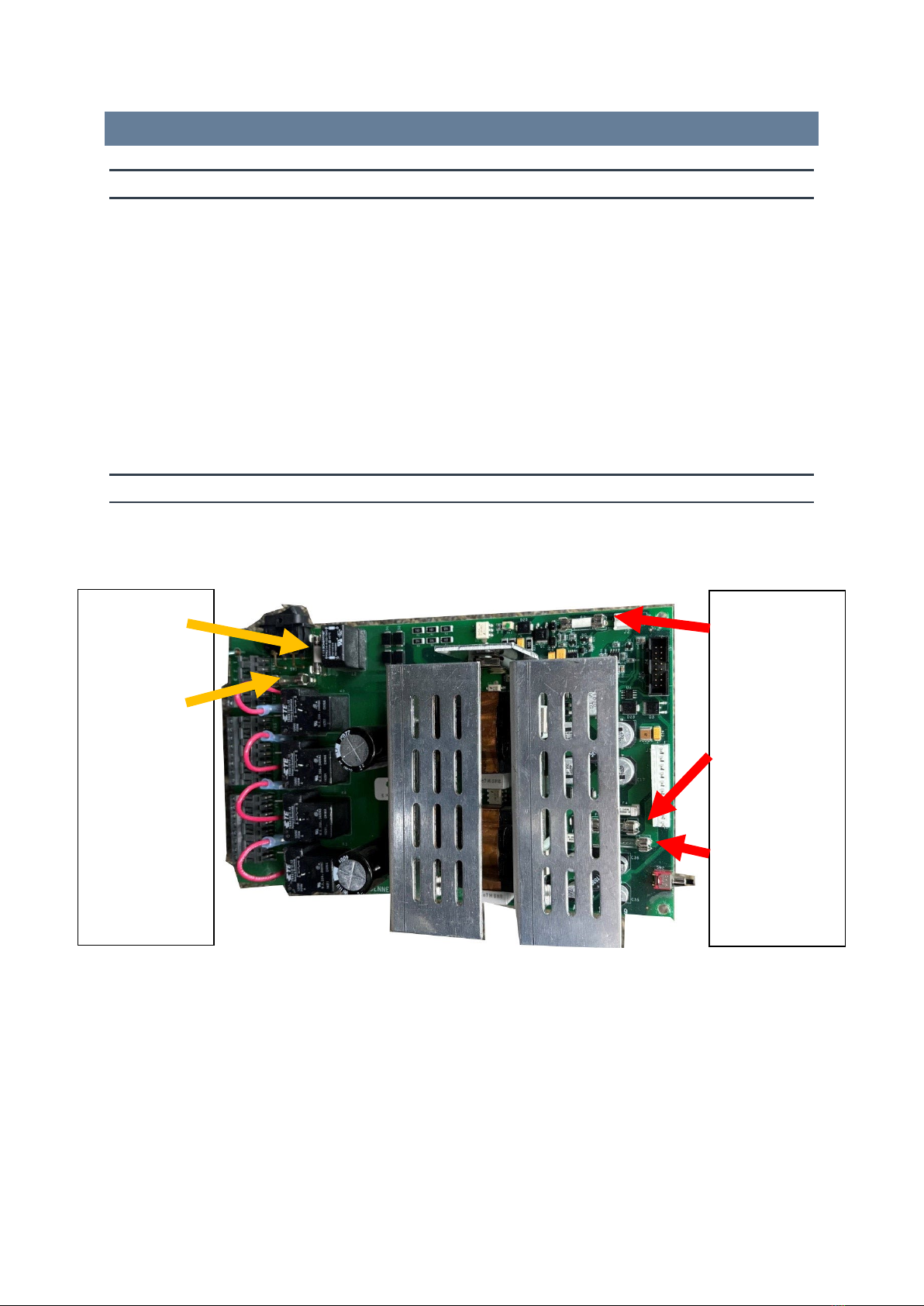
3.3.2 819 POWER BOARD FUSE LOCATIONS
The 819 Power Board has the following fuses:
Figure 3.1. 819 Power Board Fuse Locations.
F2 – Incoming
AC Power
F1 – Motor
Control Circuit
F3 – 12VDC
Backup Battery
Charging Circuit
F5 – 24VDC
Circuit
F7 – 12 VDC
Circuit
Troubleshooting Guide
H35 Maintenance Manual 7
4TROUBLESHOOTING GUIDE
For all electrical troubleshooting please refer to the wiring diagrams.
4.1 PROGRAMMING AND COMMUNICATION
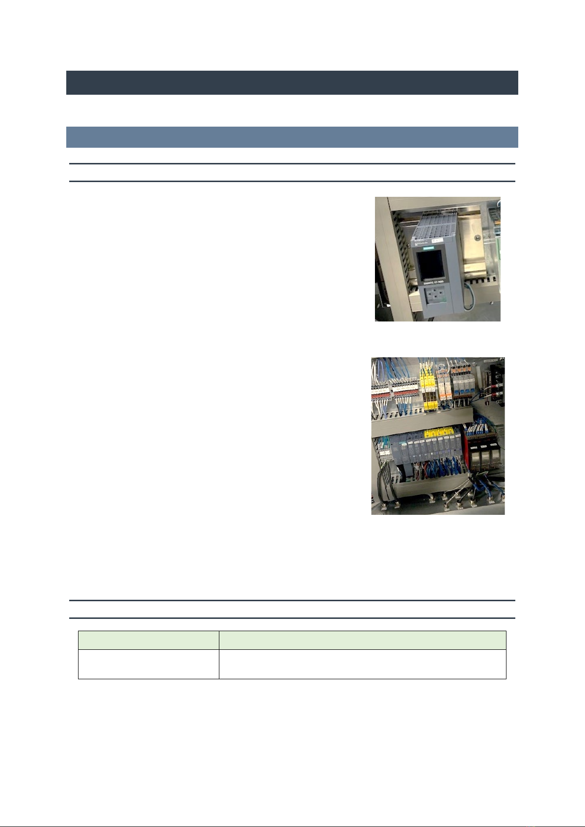
4.1.1 PROGRAMMABLE LOGIC CONTROLLER (PLC)
The PLC, as seen in Figure 3.2, is linked to a remote I/O board
responsible for managing the modules on the rack, depicted in
Figure 3.3.
If the Run state shows a green light, the rack and PLC are
functioning properly.
If red lights are displaying check the following:
•Verify CPU has booted up.
•The PLC monitor shows navigable information, controlled
via the pad beneath it. This helps narrow down the issue.
•Card seated properly – I/O card rack
•Check for damaged card.
•If it is a safety card (yellow) verify plug is on the back side
of the card.
•ET200SP connected to the PLC
•Verify wiring is correct
4.1.2 MANAGER’S KEYPAD WON’T ENTER PROGRAMMING MODE
Problem
Solution
A handle switch has been
activated.
Make sure all the handles are hung up. The system cannot enter
Managers mode if a handle is removed.
Figure 3.2. PLC
Figure 3.3. Remote I/O Card and
Rack.
Troubleshooting Guide
H35 Maintenance Manual 8
4.1.3 DISPENSER COMMUNICATION
Problem
Solution
The dispenser is in Stand Alone
mode.
Program the dispenser in Mode 21 for the correct communication
type. See the Hydrogen Operation Manual.
The handle switch is not
working properly.
Make sure the handle switch is working properly by running
diagnostics mode 5. If not, the handle switch, handle switch cable,
barrier board, or 819 could be the problem. Troubleshoot as needed.
Bad Intrinsically Safe Barrier
Board (ISB) or loose cable.
Check to make sure the handle switch cable is making good contact
with the connector. Replace ISB if necessary, with a known good one.
The 515 box has lost
communication.
Perform a RAM Clear in Mode 49 in the 515 Box. Verify the 515 Box
is ON. Check the cable connections.
Maximum wire length from the
dispenser to the 515 Box.
Make sure that there is no more than 1000 feet between the
dispenser and the 515 box.
Check the Point-of-Sale system
for proper programming.
Is the Point-of-Sale set up for “Handle up Calling”?
Installation Wiring
Verify with the Wiring Diagram.
Ribbon Cable between CPU
Board and Power Board.
Make sure that the connections are snug. Replace cables that are
damaged.
Troubleshooting Guide
H35 Maintenance Manual 9
4.2 POWER AND DISPLAY
4.2.1 NO POWER
If the dispenser has no power, follow these steps to diagnose and resolve the issue:
Step
Action
Description
1 Check the Power Switch Confirm that the power switch on the 819 Power Board is in the
ON position.
2
Verify AC Power Supply
Check that the dispenser is receiving AC power.
3 Check Battery Status Verify that the 12V battery in the dispenser is charged. A dead
battery can prevent the dispenser from turning ON.
4 Purge Cabinets (for dispensers
with purge cabinets)
Confirm a positive pressure in the electrical cabinet.
Verify that the purge pressure switch is activated.
Note: It may take up to 4 minutes for the dispenser to power ON
after applying the purge.
5 Gas Detector (for dispensers
with a gas detector)
Verify that the gas detector has power.
Check the gas reading is at 0% LEL.
Note: It may take up to 4 minutes for the dispenser to power on
after applying the purge.
6 Bypass Switch (if safe to use) There is a bypass switch on the timer board for troubleshooting
purposes. Press it to power on the dispenser if it's safe to do so.
4.2.2 THE DISPLAY AMOUNT AND POINT OF SALE AMOUNT DON’T MATCH
Problem
Solution
Incorrect setting for “rounding”
in the dispenser.
Check the dispenser rounding setting. See Menu Code 28: Rounding,
in the Operation Manual.
Troubleshooting Guide
H35 Maintenance Manual 10
4.2.3 BLANK DISPLAY
Problem
Solution
The dispenser is turned OFF.
Check the power switch inside the dispenser. Turn it on.
Blown Fuse Check the system fuse on the Power Board. Refer to the Power
Board section.
The dispenser has been turned
OFF from the main power panel.
Turn on the breaker for this dispenser inside the building.
Bad Display Board
Replace the Display Board with a known good one.
Bad CPU
Replace the CPU with a known good one.
4.2.4 DISPLAY SEGMENTS DISTORTED
Problem
Solution
The display board is broken. Run diagnostics on the display. Do all the segments light up? If not,
replace the Display Board.
Loose cable in the electronics. Check the cables going to the Display Board.
Distorted segments. Plug in the manager’s keypad. Press +/- five times to change the
segments. Stop when the display shows “Enter Side 1”.
4.2.5 DECIMAL PLACE IN WRONG POSITION
Problem
Solution
Programming problem. Check modes 8 and 99
4.2.6 NO DISPENSER BACKLIGHT
Problem
Solution
The dispenser is in power fail. When main power returns to the dispenser the light should come
back on.
The cable came loose from the
Display Board to the Backlight
board.
Check the small power cable for lighting that connects the Display
Board to the Backlight Board.

Troubleshooting Guide
H35 Maintenance Manual 11
4.3 HYDROGEN DISPENSING
4.3.1 DISPENSER HAS NO FLOW
Problem
Solution
Supply Pressure: No Pressure Verify that the hydrogen supply pressure
is within the required range.
No flow, no power. The dispenser is OFF Turn ON the dispenser
Check valve operation
: The valve is not
opening.
Inspect the valves to make sure they are
open and not clogged.
Verify that the valve is opening by measuring
voltage on the 24VDC circuit. Refer to the
CPU board section for guidance.
The dispenser is not authorized.
If connected to a POS, be sure that the POS
is sending authorization. Refer to the Point-
of-Sale reference manual.
Program the
dispenser to be in stand-
alone mode and
test.
The POS did not authorize the dispenser OR
the station has not informed the dispenser
that hydrogen is available.
The CPU is locked up.
Power down the dispenser and bypass the
battery. Power up the dispenser and retry
the operation.
The maximum allocation is set to zero.
Change the allocation setting in
programming to a higher number (e.g., set
to 99).
The nozzle is broken. Replace the damaged nozzle.
The hoses are hung up in the wrong nozzle
boots.
Make sure the hoses are correctly positioned
in their respective nozzle boots.
Hose quality: Hose kinks, damaged. Verify that the hoses are properly connected
and not kinked or damaged.
Bad handle switch. Replace the handle switch if found to be
defective.

Troubleshooting Guide
H35 Maintenance Manual 12
4.3.2 SLOW DISPENSING FLOW
Problem
Solution
Pressure
Verify that the hydrogen supply pressure is within the required range.
Valves
Check that the manual shut off valve at the inlet of the dispenser is fully open.
Power
Confirm that the dispenser's power source is operational.
Hoses
Verify that the hoses are properly connected and not kinked or damaged.
Filter Check the filter located in the lower cabinet for a clog. Clear any debris. See Section 9,
Appendix B of this manual.
4.3.3 INACCURATE PRESSURE READING
Problem
Solution
Calibration Be sure the dispenser is properly calibrated. See the installation manual for calibration
procedures.
External
Interference
Check that there are no strong electromagnetic fields or sources of interference near
the dispenser.
4.3.4 DISPENSER LEAK
Steps
Solution
Is there a dispenser leak?
Evacuate the dispensing area immediately if a leak is detected.
Emergency Shutdown Shut down the dispenser using emergency shutdown on the
dispenser exterior.
Isolate Leak
Isolate the dispenser from the hydrogen supply source.
Ventilation
Provide proper ventilation to disperse leaked hydrogen.
Professional Inspection Contact a hydrogen equipment professional to identify and repair
the leak.
4.3.5 VALVE OR VALVES NOT OPENING
Problem
Solution
Loss of +24VDC.
Troubleshoot the +24vdc signal. Call Technical Support.
Bad Valve.
Replace Valve with a known good one.
Loss of instrument air.
Check breakers in the dispenser. See wire diagram.
Troubleshooting Guide
H35 Maintenance Manual 13
4.3.6 DISPENSER STOPS PUMPING AFTER SEVERAL SECONDS
Problem
Solution
The dispenser stops pumping
after several seconds
See Section 7 Fill Termination Reason Codes.
4.3.7 THE ELECTRONIC DISPENSER HEAD IS WET
Problem
Solution
The door locks are not closed
properly.
Close and lock the doors properly.
Door Lock brackets are bent.
Adjust door lock brackets or replace.
Reuse of gasket when a
component is replaced.
Always replace the gasket when installing a new component.
Unknown water intrusion
Call Bennett Technical Support (800) 423-6638.
Dispenser Error Messages
H35 Maintenance Manual 14
5DISPENSER ERROR MESSAGES
Common solutions to error code messages:
•Power Cycle: Try turning the dispenser OFF and ON again to clear minor errors.
•Reboot Dispenser:Use Mode 49 to reboot the dispenser.
•Clear Memory: Use Mode 58 to wipe the memory including all programming and calibration
values.
•Software Update: Check for software updates that might resolve error messages.
•Raise and Lower the Handle Switch: To clear error codes. Do this twice if initial power up
sends and Emergency Stop Error.
5.1 ERROR CODES
Error codes are displayed when there is a fault condition in the dispenser. In the event of an error, a
message will be displayed on the side of the dispenser where the error occurred.
Any error message will shut down the sale but not disable the dispenser. To clear an error message,
follow these steps
1. Pick up the nozzle from its boot.
2. Raise and then lower the handle switch.
3. The error code is cleared unless this is an initial power up and an Emergency Stop Error has
occurred. If so, repeat this process twice to clear the Emergency Stop Error.
4. Raise the switch again to continue with the sale.
Use the dispenser diagnostics to determine the problem or to view the error history log refer to the
H35 Operators Manual (Diagnostic Code 2) for more information. Note: Repair the problem that may
have caused the error first and then clear the message.
Error
Code
Error Description Troubleshooting Steps
02 DATA: There is a failure or error with the
RAM
Try to reboot the dispenser.
If needed, move to Power Cycle.
If needed, move to Clear Memory.
03 PRESSR: The pressure at the dispenser is
not at a safe level
Adjust the pressure before continuing.
11 TEMOOR: The ambient temperature is out
of range.
Check temperature readings of thermocouples on
the IS barrier.
Check environmental factors affecting
thermocouples.
Consider the ambient temperature's safety range
for filling.
Verify wiring for thermocouples and barrier is
correct.
Dispenser Error Messages
H35 Maintenance Manual 15
Error
Code
Error Description Troubleshooting Steps
13 HIPRES: The pressure is above the limit of
the dispenser
Lower the pressure before continuing.
14 MtCOMM: Communication issue with the
mass flow meter
Verify the wiring is correct.
Check the meter Modbus settings on the meter
transmitter.
Check the PLC I/O Card for the meter.
15 PLC819: Communication issue between
819 CPU and the PLC
Verify termination resistors are present.
Follow similar steps as Error 14.
16 AMBTEM: The ambient temperature is not
reading.
Verify the thermocouple is not broken.
Verify wiring for thermocouples and barrier is
correct.
17 GASTEM: The hydrogen gas temperature is
not reading.
Verify the thermocouple is not broken.
Verify wiring for thermocouples and barrier is
correct.
18 GASPRS: The hydrogen gas pressure is not
reading.
Verify the pressure sensor is not broken.
Verify correct the wiring and functioning of Analog
Input Card.
19 REGVLV: The flow control valve in the
dispenser is malfunctioning
Open and close the valve.
Verify the valve is opening and closing.
Check the feedback signal.
Verify wiring is correct.
20 FILVLV: The fill valve is malfunctioning
Actuate the valve to verify opening and closing.
Check the circuit breaker if present.
Check the wiring, and verify the valve receives
proper power.
21 HOSTEM: The host temperature is not
reading.
Follow the same steps as Error 17.
22
HOSPRS: The hose pressure is not reading.
Follow the same steps as Error 18.
23 ESTOP: Emergency Stop (ESTOP) issues
An ESTOP error may show up when the dispenser
powers up for the first time.
Check if the ESTOP button on the dispenser is
pressed.
If so, verify the reason for pressing.
Pull the ESTOP button out.
Clear the error following the acknowledgement
procedure.
If the error persists, verify correct wiring for ESTOP
button and control relays.

Dispenser Error Messages
H35 Maintenance Manual 16
Error
Code
Error Description Troubleshooting Steps
24 ACK Needed: Acknowledgment needed for
ESTOP error
Try to clear the error following the
acknowledgement procedure.
Check the wiring of the ESTOP circuit and control
relays.
25 rcGTEM: The gas temperature redundancy
check has failed
Compare the readings of the two thermocouples.
Check wiring and calibrate sensors if needed.
26 rcGPRS: The gas pressure redundancy
check has failed
Compare the readings of the two pressure sensors.
Check wiring and calibrate sensors if needed.
29
GASDET: Gas detector issues.
Indicates that both gas detectors are not
communicating. If A2 is also shown, then
both detectors are in an alarm state.
Verify correct wiring for both gas detectors.
30
GASDT1: Gas detector issues (CG-100)
Verify correct wiring for both gas detectors.
38 GASDT2: Gas detector issues (CG-200)
Verify correct wiring for both gas detectors.
Check the gas detector's voltage.
Verify the addresses match the 819 CPU and the
gas detector.
Verify the baud rate and stop bits on the gas
detector.
For the A2 alarm, check for hydrogen leaks.
Track down the hydrogen leak and repair.
Verify the leak is no longer present.
If no leak is found, check the gas detector reading
with a hydrogen calibration bottle.
If needed calibrate the gas detector.
40,
41
Meter Issues: Potential issue with the
meter
Use diagnostic mode to read the last 10-meter
faults.
Check the meter manual for more details on faults
found.
42 VVOPFA: Vent valve has failed to open
Check the hose pressure reading. If the reading is
above 0.5 MPa the pressure needs to reduce below
0.5 MPa before the error can be cleared.
Toggle the vent valve ON and OFF to check if it will
open and close.
If the valve does not move, verify air pressure and
electrical to the valve is correct.
43
VVCLFA: Vent valve has failed to close
Follow the same steps as Error 42.
Dispenser Error Messages
H35 Maintenance Manual 17
Error
Code
Error Description Troubleshooting Steps
44 FVCLFA: Fill valve failed to close
Verify valve stays closed by monitoring pressure
sensors before and after the fill valve.
When the valve is open those pressure sensors
should be the same.
When the valve is closed the pressure can be
vented down on outlet side of the valve.
The outlet pressure should decrease, and the inlet
pressure should not decrease.
If it does decrease and it is confirmed that the valve
is not energized, then rebuild or replace the valve.
45 FVOPFA: Fill valve failed to open
Verify pressure on the inlet of the fill valve is higher
than the outlet
Open the fill valve
Verify pressure equalizes; if not, check the
energization of the valve
If not, rebuild and replace the valve
46 PLCCOM: Communication loss between
station PLC and dispenser PLC
Verify correct wiring
Verify Modbus parameters
Try a power cycle
47 VIBACT: Vibration switch in the dispenser
is activated
Reset the vibration switch and clear the error
Adjust the setpoint of the vibration switch if
needed
Verify correct wiring
60 POSTAL: General error
Try to reboot the dispenser.
If needed, move to Power Cycle.
If needed, move to Clear Memory.
70 NOECAL: Electronic calibration value issue Verify the calibration value in the 819 CPU is set
properly
71 RANGE: Electronic calibration value is out
of range
Verify the calibration value is set properly
74 UNSEAL: The calibration switch on the 819
CPU is ON
Slide the switch to the OFF position and seal it
closed
99 GENERL: General error
Try to reboot the dispenser.
If needed, move to Power Cycle.
If needed, move to Clear Memory.
nn UNDEFI: Undefined error
Update 819 CPU and PLC to the latest software
version.
Please report to Technical Support (800) 423-
6638.
Other manuals for H35 Series
2
Table of contents
Other Bennett Marine Equipment manuals

Bennett
Bennett BOLT Control BCI8000 User manual

Bennett
Bennett H35 Series User manual

Bennett
Bennett H35 Series User manual

Bennett
Bennett SITE MASTER EMV User manual

Bennett
Bennett LNG Series User manual

Bennett
Bennett HIGH FLOW H35 User manual

Bennett
Bennett BOLT Rocker BRC4000 User manual

Bennett
Bennett 621 User manual


