Bennett SITE MASTER EMV User manual

Bennett 1218 E. Pontaluna Road, Spring Lake, MI 49456
USA 800-235-7618 ~ Outside USA 231-798-1310
sales@bennettpump.com ~ www.bennettpump.com
BENNETT SITE MASTER EMV ASSEMBLY
Site Master EMV Instruction Manual
144332 Rev A 11/4/2020
Safety Information | Installation | Operation | Maintenance | Parts | Schematics
Only Trained Personnel May Work on This Equipment
READ THIS MANUAL
This manual has important information for safe installation and operation of this equipment. Read and understand this manual before
applying power. Keep this manual and tell all service personnel to read this manual. If you do not follow the instructions, you can cause
bodily injury, death, or damage to the equipment.

Bennett 1218 E. Pontaluna Road, Spring Lake, MI 49456
USA 800-235-7618 ~ Outside USA 231-798-1310
sales@bennettpump.com ~ www.bennettpump.com
The material included in this installation manual is accurate at the date of publication. The intent of this manual is to assist.
If further assistance is required, please contact the Bennett Technical Service Department at 1-800-423-6638.
Bennett Marketing Services can be contacted by mail, facsimile, telephone or e-mail at the locations specified below:
Bennett Pump Company
Marketing Services
1218 East Pontaluna Road
Spring Lake, MI 49456
Telephone from USA 1-800-235-7618
Telephone from outside USA 231-798-1310, Extension 287 or 269
Customer Service USA 231-719-6050; Facsimile USA 231-799-6202
Website: www.bennettpump.com
For new manuals, visit our web page at www.bennettpump.com
IMPORTANT
Examine the shipment immediately upon arrival to make certain there has been no damage or loss in transit. Bennett
Pump Company, as shipper, is not liable for the hazards of transportation. Please make damage claims directly to the
truck line.
NOTICE: This device complies with part 15 of the FCC rules. Operation is subject to the following two conditions: (1) This
device may not cause harmful interface, and (2) this device must accept interference received, including interference that
may cause undesired operation.
RELATED DOCUMENTATION
132544 - Simply Secure Payment PCI 3.1 (Large Display w/ SBC2) Programming, Service, and Parts Manual
125927 (P4208) –Site Master SP Footprint
126000 (P4429) -Site Master Wiring Diagram
Revision
Date
Description
0
10/27/20
Original Document

Bennett Site Master Instruction Manual Table of Contents
i
TABLE OF CONTENTS
IMPORTANT SAFETY INSTRUCTIONS 3
General Information..........................................................................................................................................................................................................................4
Hazardous locations..........................................................................................................................................................................................................................4
Codes and Standards........................................................................................................................................................................................................................4
Unauthorized Alteration of Bennett Products .......................................................................................................................................................................4
Abbreviations and Acronyms........................................................................................................................................................................................................4
INSTALLATION 5
Specifications .......................................................................................................................................................................................................................................5
Recommended Materials................................................................................................................................................................................................................5
Dispenser Overview...........................................................................................................................................................................................................................6
Mechanical Installation Requirements ......................................................................................................................................................................................7
Site Master SP Footprint .................................................................................................................................................................................................................8
Wiring Instructions ............................................................................................................................................................................................................................9
Determining the Number of Wires Required.........................................................................................................................................................................9
Point of Sale (POS) Communication...........................................................................................................................................................................................9
Beginning the Wiring Process....................................................................................................................................................................................................10
Installing Conduit at the Site Master ......................................................................................................................................................................................10
OPERATION 13
Door Key Locks.................................................................................................................................................................................................................................13
SSP Payment Module ....................................................................................................................................................................................................................14
Gaining Access to Managers Mode......................................................................................................................................................................................... 14
MAINTENANCE 15
Fuse Board (P/N 130809).............................................................................................................................................................................................................15
Power Supply Board (P/N 111209) ..........................................................................................................................................................................................16
Cleaning ..............................................................................................................................................................................................................................................17
PARTS 19
To Place an Order for Parts.........................................................................................................................................................................................................19
Door Upper Alpha Numeric/EMV 7” Display (P4913s2) .................................................................................................................................................20
SCHEMATICS 21
Field Wiring........................................................................................................................................................................................................................................21
Footprint .............................................................................................................................................................................................................................................23

Bennett Site Master Instruction Manual Table of Contents
ii
Page Intentionally Left Blank
Bennett Site Master Instruction Manual Safety Instructions
3
IMPORTANT SAFETY INSTRUCTIONS
For safe installation of this equipment, read and understand all dangers, warnings, cautionary, and important information. Save these
important safety instructions in a readily accessible location. Look for the following warnings throughout the manual:
Red and White “DANGER” means: If you do not follow the instructions, severe injury or death will occur.
Orange and Black “WARNING” means: If you do not follow the instructions, severe injury or death can occur.
Yellow and Black “CAUTION” means: If you do not follow the instructions, damage can occur to the dispenser.
Blue and White “IMPORTANT” means: Helpful tips and other recommendations on equipment installation, usage, and maintenance
should be observed.
DANGER PELIGRO DANGER
FIRE, EXPLOSION, INJURY, OR DEATH WILL OCCUR IF FUEL FILTERS ARE CHANGED BY UNTRAINED PERSONNEL.
MAKE SURE, ONLY TRAINED PERSONNEL CHANGE FILTERS.
TO PREVENT INJURY TO YOU FROM VEHICLES AND ONLOOKERS, ALWAYS PLACE A BARRIER AROUND THIS
EQUIPMENT BEFORE PERFORMING SERVICE OR MAINTENANCE.
GASOLINE IS FLAMMABLE. NO SMOKING OR OPEN FLAME.
DISCONNECT ALL POWER AND RELIEVE PRESSURE TO THIS EQUIPMENT AND ASSOCIATED SUBMERGED
PUMP(S) DURING INSTALLATION, SERVICE, OR ANY MAINTENANCE I.E., CHANGING FILTERS.
WARNING ADVERTENCIA MISE EN GARDE
You must have training in the installation, service, or maintenance of this equipment (dispenser, pump, site
master, console, control box, payment terminal, or submerged pump) before working on it. Maintenance repairs
must be done by authorized personnel only. Warranty work may only be performed by Bennett certified
technicians.
To prevent electric shock, keep the electrical parts of the Site Master dry.
Electronic components are static sensitive. Use proper static precautions (e.g. static straps) before working on
the equipment.
The emergency shut-off valve (also called the fire valve, shear valve, or impact valve) must be closed when
service or maintenance is performed on this equipment.
You must have training in the operation and programming of this Site Master Payment Terminal before using it.
READ THE OPERATORS MANUAL.
Make sure this equipment is correctly grounded. Failure to do will cause injury or damage equipment or
improper operation. Improper grounding voids the warranty.
Do not operate the equipment as a payment terminal unless it is completely assembled.
CAUTION PRECAUCIÓN MISE EN GARDE
Do not drill holes in the Site Master. Holes can cause failure of the electronic equipment. THE
WARRANTY WILL BECOME VOID. Use only adhesive backed sign mounting brackets.
IMPORTANT IMPORTANTE IMPORTANT
All trained technicians must work in accordance to all requirements, standards, and guidelines specified by the
suppliers Environmental Standards® Health, Safety, Security & Environment (HSSE) policies. Note: Bennett Pump
highly recommends all technicians observe HSSE policies defined by the supplier. Bennett Pump does not impose
any restrictions or additional requirements contained in Environmental Standards® Health, Safety, Security &
Environment (HSSE) policies.
!! READ AND UNDERSTAND ALL WARNING LABELS ATTACHED TO THE DISPENSER !!

Bennett Site Master Instruction Manual Safety instructions
4
GENERAL INFORMATION
Read this manual carefully and read all tags/labels attached to the Site Master before starting any maintenance and/or service. A Site
Master that is not properly maintained will not perform properly and will void the Bennett Limited Warranty.
Before installation, operation, maintenance and/or service ensure that protection against lighting strikes are in accordance with the
American Petroleum Institute Recommended Practice RP 2003, Protection Against Ignitions Arising out of Static, Lightening, and Stray
Currents.
Service of the Bennett products and all accessories must be performed by a technician who is trained in accordance to all codes, standards,
and regulations.
HAZARDOUS LOCATIONS
For safe operation, ensure that the dispenser is in a classified area as detailed below per NFPA 30, Flammable and Combustible Liquids
Code and NFPA 70, National Electric Code. For further information on the classification of locations for Fuel Dispensers, see NFPA 30,
Flammable and Combustible Liquids Code.
CODES AND STANDARDS
Follow all local, state, and federal requirements for installation of all equipment.
API 2003 –Protection Against Ignitions Arising Out of Stray, Lightning, and Stray Currents
NFPA 30 –Flammable and Combustible Liquids Standard
NFPA 30A –Motor Fuel Dispensing Facilities Standard
NFPA 70 –National Electric Code
International Fire Code –2018 Edition
UNAUTHORIZED ALTERATION OF BENNETT PRODUCTS
DANGER: BEFORE PERFORMING ANY TYPE OF SERVICE TO THE DISPENSERS, BE SURE TO SHUT OFF ALL ELECTRICAL
SUPPLIES AND SECURE THEM IN THE OFF POSITION. CLOSE ALL VALVES IN INCOMING PIPING. MAINTENANCE
MUST BE PERFORMED BY TRAINED PERSONAL ONLY.
Bennett Pump Company products are designed to meet or exceed the standards of Underwriters Laboratories, Inc., Federal
Communication Commission, and National Institute of Standards and Technology. Compliance with these standards protects the operator
and the consumer from personal injury and ensure an accurate delivery of product. Any deviation from the use of authorized
replacement parts or alteration of a designed product configuration may cause personal injury, death or the revocation of one or all of
the above approvals.
Bennett Pump Company will not assume responsibility or liability for any consequential injury or damage caused by the unauthorized
alteration of its products.
ABBREVIATIONS AND ACRONYMS
AC
Alternating Current
CPU
Central Processing Unit
DC
Direct Current
FCC
Federal Communications Commission
Hz
Hertz
IFC
International Fire Code
NEC
National Electrical Code
NIST
National Institute of Standards and Technology
No.
Number
PCI
Payment Card Industry
POS
Point of Sale
Qty.
Quantity
SBC
Single Board Computer
SSC
Security Standards Council
SSP
Simply Secure Payment
THHN
Thermoplastic High Heat-resistant Nylon-coated
UL
Underwriters Laboratories, Inc.
VAC
Voltage Alternating Current
VASC
VeriFone Authorized Service Contractor
VDC
Voltage Direct Current
W&M
Weights and Measures

Bennett Site Master Instruction Manual Installation
5
INSTALLATION
Examine the shipment immediately upon arrival to make certain there has been no damage or loss in transit. Bennett Pump Company, as
shipper, is not liable for the hazards of transportation. Please make damage claims directly to the truck line.
Please read these instructions carefully and read all tags attached to the Site Master before starting installation. A Site Master Payment
Terminal that is not properly installed will not perform properly and will void the limited warranty. All other equipment manufacture’s
installation instructions must be followed. Bennett Pump does not provide other manufacture’s installation instructions and are not
responsible for any potential problems.
Installation must be in accordance with the National Fire Protection Agency NFPA 70: National Electrical Code (NEC), NFPA 30A: Code for
Motor Fuel Dispensing Facilities and Repair Garages, NFPA 30: Flammable and Combustible Liquids Code, International Fire Code (IFC),
and all state and local codes.
SPECIFICATIONS
DIMENSIONS
Refer to Footprint Diagram (125927 –P4208) located inside the Site Master or on the USB provided.
Site Master Series Maximum.................................................................................................... 19 25/32” (width) x 12 ¼” (depth) x 42” (height)
Site Master Series Estimated Shipping Weight...........................................................................................................130 pounds/59 kilograms
POWER REQUIREMENTS
DANGER: INCOMING AC POWER AT TS1 OF THE TIMER BOARD WILL REMAIN ACTIVE IF THE MAIN CIRCUIT BREAKER(S) ARE
NOT TURNED OFF.
WARNING: TO PREVENT ELECTRIC SHOCK, MAKE SURE THE CURRENT IS OFF AT THE CIRCUIT BREAKER(S) AND THE BREAKER IS
LOCKED OUT BEFORE DOING ANY REPAIRS OR MAINTENANCE TO THE DISPENSER.
CAUTION: THE INTRINSIC SAFETY GROUND WIRE MUST BE FIRMLY
AC Power Input, Electronic.................................................................................................................120/240 VAC, 50/60 Hz. 350 Watts Max.
DC Power Supply Output ........................................................................................................................................+12 VDC at 2.00 Amps Max.
+24 VDC at 2.00 Amps Max.
Lead-Acid Battery Output .......................................................................................................................................... +12 VDC at 2.0 Amp Max.
Nickel-Cadmium Battery Output .......................................................................................................................+3.6 VDC at 250 Milliamp Max.
ENVIRONMENTAL REQUIREMENTS
Operating Temperature Range....................................................................................................................... -40°C to +65°C (-40°F to +149°F)
Humidity ........................................................................................................................................................................ 0-95% non-condensing
RECOMMENDED MATERIALS
Note: Any Site Master must only use Underwriters (U.L) Listed equipment.
Anchor Bolts
Lifting device to lift and transport the Site Master.
Personal Barriers
Potting Compound National Fire Protection Agency NFPA 70: National Electrical Code (NEC) approved.
Static Straps
Multi-Meter
Bennett Site Master Instruction Manual Installation
6
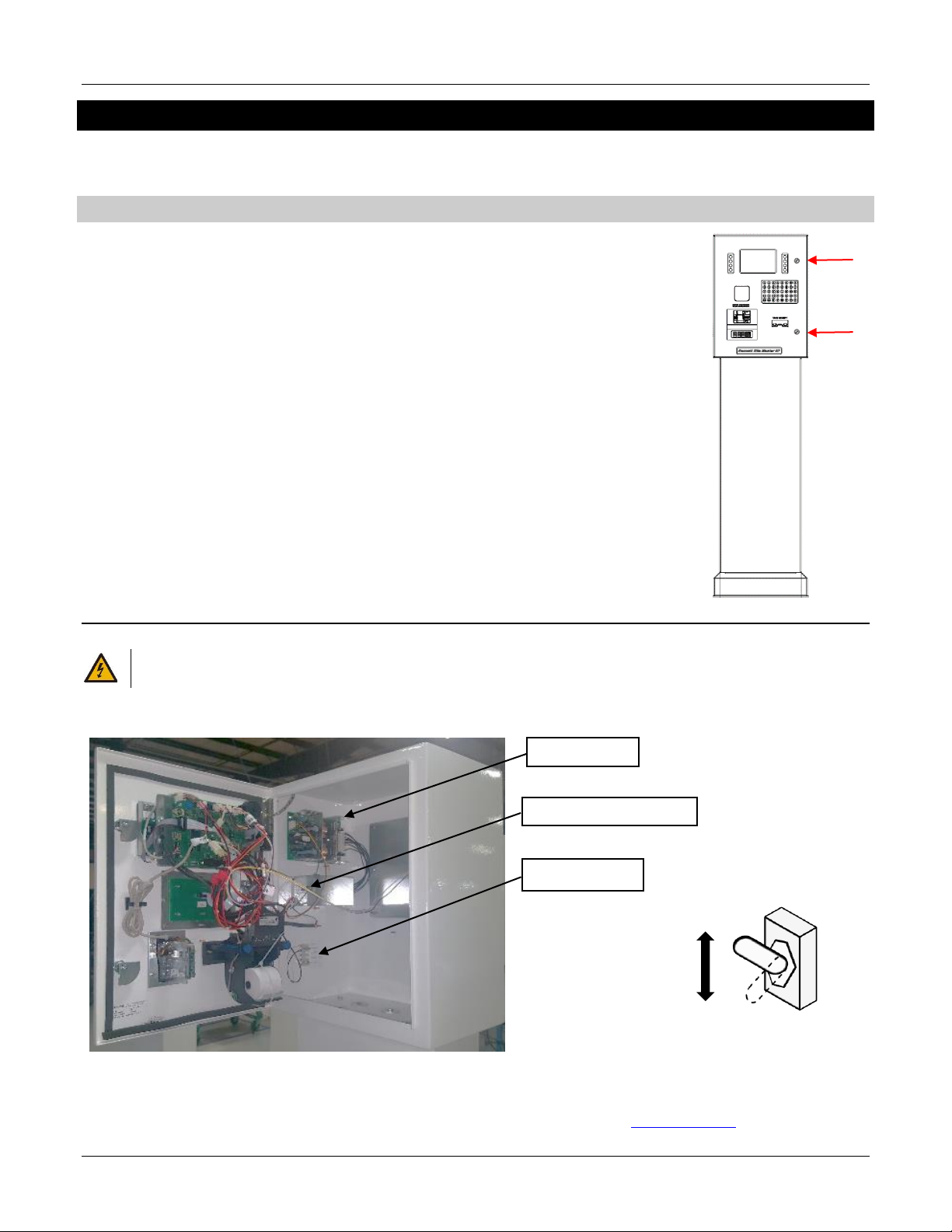
DISPENSER OVERVIEW
EXTERIOR LAYOUT (ALPHA NUMERIC)
INTERIOR LAYOUT
120VAC is installed in the head of the unit and terminated on the terminal strip as shown in Figure 1.2. Neutral and Hot are labeled on
the terminal strip. The Power Supply is factory wired to the terminal strip and converts the 120VAC into the +12VDC and +24VDC needed
for the module to operate.
The payment module receives power from the Power Supply through the J5 connector on the SBC2 CPU Board and uses a +12 VDC
voltage source and +24 VDC voltage source. Both sources are received through the J5 connector.
Figure 0.1 - Exterior Layout with EMV & Alpha
Key Locks
Receipt Printer
EMV PIN Pad
7” Display
NFC Reader
Power Supply
Power Toggle Switch
SBC2 CPU Board
Terminal Strip
Figure 0.2 - Interior Layout with EMV & Alpha
Bennett Site Master Instruction Manual Installation
7
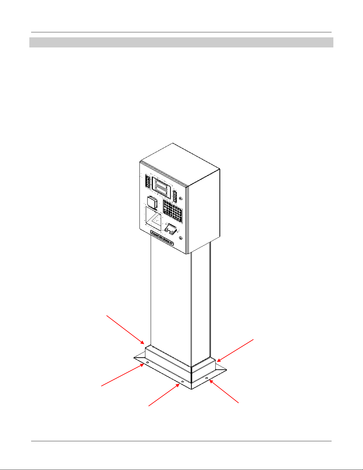
MECHANICAL INSTALLATION REQUIREMENTS
Note: The Site Master must be mounted on a concrete foundation and at least 10 ft. (3 m) from any building opening. Follow the
procedure below for mounting instructions.
1. Refer to the Site Master SP Footprint Diagram (125927 – P4208) shown on the next page or on the USB provided located inside the
unit for conduit connections for the Site Master.
2. Anchor the Site Master to the island with four ½” bolts anchor bolts through the base frame. Note: When anchoring the Site Master,
always level the unit with shims before bolting to the island. DO NOT SHIM MIDDLE OF RAIL BASE TO BOLT DOWN THE SITE MASTER.
SHIM ONLY NEAR BOLTS. Figure 1.3
3. Place the shims at the location of the anchor bolts so the Site Master frame is not distorted when the anchor bolts are tightened down.
Note: THE SITE MASTER MUST BE BOLTED TO THE ISLAND. DO NOT SKIP THIS STEP.
Figure 0.3 –Anchor Bolt Locations
Bennett Site Master Instruction Manual Installation
8
SITE MASTER SP FOOTPRINT
Refer to Footprint Diagram (125927 –P4208) located inside the Site Master or on the USB provided. Note: Information below is subject
to change without notice and some options shown are not available on all models.
DIMENSION NOTES:
1. Dimensions are in Inches
2. Inside opening in lower enclosure = 8-13/16” x 10-13/16"
INSTALLATION NOTES:
A. Installation must be in accordance with national electric code (NFPA 70), The Automotive and Marine Service Code (NFPA 30A), and
all state and local codes
B. Use only Underwriters Listed Threaded Rigid Conduit and Listed Sealing Fittings with conductor Seals.
C. Field connections are done in the upper electrical enclosure. Wire must extend 60 inches above base of the Site Master to make
electrical connections.
D. Shims should only be used under bolts to ensure the Site Master is level. Improper shimming that result in misaligned frames is NOT
covered under the Bennett Limited Warranty.
Figure 0.4 –Footprint

Bennett Site Master Instruction Manual Installation
9
WIRING INSTRUCTIONS
DETERMINING THE NUMBER OF WIRES REQUIRED
Use this section as a guide to determine the wires needed for installation.
STEP 1 - AC POWER WIRES (240 WATTS 115/120V 50/60 HZ)
Power is supplied by the Power Board.
1 x 12ga. Green Earth Ground
1 x 14ga. White Electronic Power - Neutral
1 x 14ga. Black Electronic Power - Hot
STEP 2 –RS-485 PAYMENT MODULE COMMUNICATION WIRES
The electronics communicate using a 3-wire RS-485 communication. RS-485 is a communication interface that uses multiple receivers for
signaling. Follow the recommended color-coding found in the wiring diagram.
1 x 18ga. Violet RS-485 (+ positive)
1 x 18ga. Common
1 x 18ga. Yellow RS-485 (- negative)
RS-485 wires should be twisted together no less than 3 turns per foot to reduce the effects of electrical noise on the communication
circuit. Due to the risk of noise, causing possible problems with communication, Bennett highly recommends the use of twisted wires, but
does not require it. Note: Belden shielded cable is accepted but the “drain” must not be terminated.
POINT OF SALE (POS) COMMUNICATION
Data for the payment module is received through the [J5] connector on the SBC2 board. The module communicates directly to the Point
of Sale through the Site Master and Interconnect Box. The Site Master only carries the data from its point of entry [J5] on the Power
Board to [J5] on the modules SBC2 Circuit Board. There is nothing in the Site Master that interfaces with this communication.

Bennett Site Master Instruction Manual Installation
10
BEGINNING THE WIRING PROCESS
WARNING: FAILURE TO PROPERLY GROUND THE EQUIPMENT CAN CAUSE INJURY OR DAMAGE TO THE EQUIPMENT
AND WILL VOID THE BENNETT LIMITED WARRANTY.
WARNING: DO NOT TERMINATE THE GROUND AT THE NEUTRAL BAR OF A SUB-PANEL OR RELY ON METAL CONDUIT
FOR THIS GROUND CONNECTION. EACH SITE MASTER’S GROUNDING POST MUST BE WITHIN 1-OHM
RESISTANCE TO EARTH GROUND POTENTIAL. DO NOT USE WIRE NUTS ON GROUND CIRCUITS, USE ONLY
COMPRESSION TYPE CONNECTORS. THIS IS REQUIRED TO INITIATE BENNETT’S LIMITED WARRANTY.
CAUTION: Do not daisy-chain ground wires. All ground circuits must be dedicated wires connected directly to the
ground bar in the main electrical panel. A direct connection to the site’s ground rod must be connected
to the ground bar in the main electrical panel.
CAUTION: Electronic power must be connected to a dedicated 15 Amp neutral breaking circuit breaker. The Site
Master is factory wired for 115/120V 50/60hz operation and must not be changed in the field. If this has
been changed in the field, the warranty is voided.
1. Remove the lower rear panel of the pedestal and locate the inlet wiring electrical conduit.
2. Remove the cover from the Power Supply by removing the lower two screws and loosening the two screws on the top backside of
the cover.
3. Place covers and screws in a location that will remind you to replace the cover once the wiring has been completed.
4. Pull the Site Master’s wires through the underground conduit and into the electronic enclosure.
5. Connect a Green Earth Ground 12-gauge (minimum), green stranded wire to the grounding lug near the Power Distribution Board.
Terminate the other end at the main electrical service panel ground bar. Note: Use 15 Amp neutral breaking circuit breakers, which
are supplied by the customer.
6. Connect AC Power
a. Connect the neutral white 14-gauge wire to position 2 of the terminal strip.
b. Connect the hot black 14-gauge wire to position 1 of the terminal strip for electronic power. Note: 120 VAC installaons L1 is
hot and L2 is Neutral.
7. Connect Data Communication Wires through ¾” conduit.
a. Connect 1 Violet 18ga. (+ positive) wire to position 3 of the terminal strip. Connect the other end to the Interconnection Box (+
positive).
b. Connect 1 White 18ga. (common) wire to position 4 of the terminal strip. Connect the other end to the Interconnection Box
(common).
c. Connect 1 Yellow 18ga. (- negative) wire to position 5 of the terminal strip. Connect the other end to the Interconnection Box (-
negative).
8. Replace covers and screws.
INSTALLING CONDUIT AT THE SITE MASTER
WARNING: Per NFPA 70, a listed seal must be provided in each conduit run entering or leaving a Site Master. The
sealing fitting shall be the first fitting after the conduit emerges from the earth or concrete.
NOTES:
All material (fittings, conductors, U-bolts, pipe clamps, etc.) running through the hydraulics must be provided by the installer
upon installation.
Check with Federal, State, and Local Codes for conduit use in your area.
Do not use PVC conduit. Use only Rigid metal conduit.
Make sure that each Site Master has its own electrical underground conduit.
Wiring from multiple Site Masters in a single conduit is not allowed.
Make sure that vapor “seal offs” are properly installed on all conduits at and from each Site Master.
Do not put non-pump related wires, such as price signs or speakers, in the same conduit as pump wiring.
All conduit between the building and each Site Master should be a separate conduit run.
For field installations, only one ¾” Female NPT Electrical Conduit is opening is available. Refer to the Site Master SP Footprint for
measurements.
Bennett Site Master Instruction Manual Installation
11
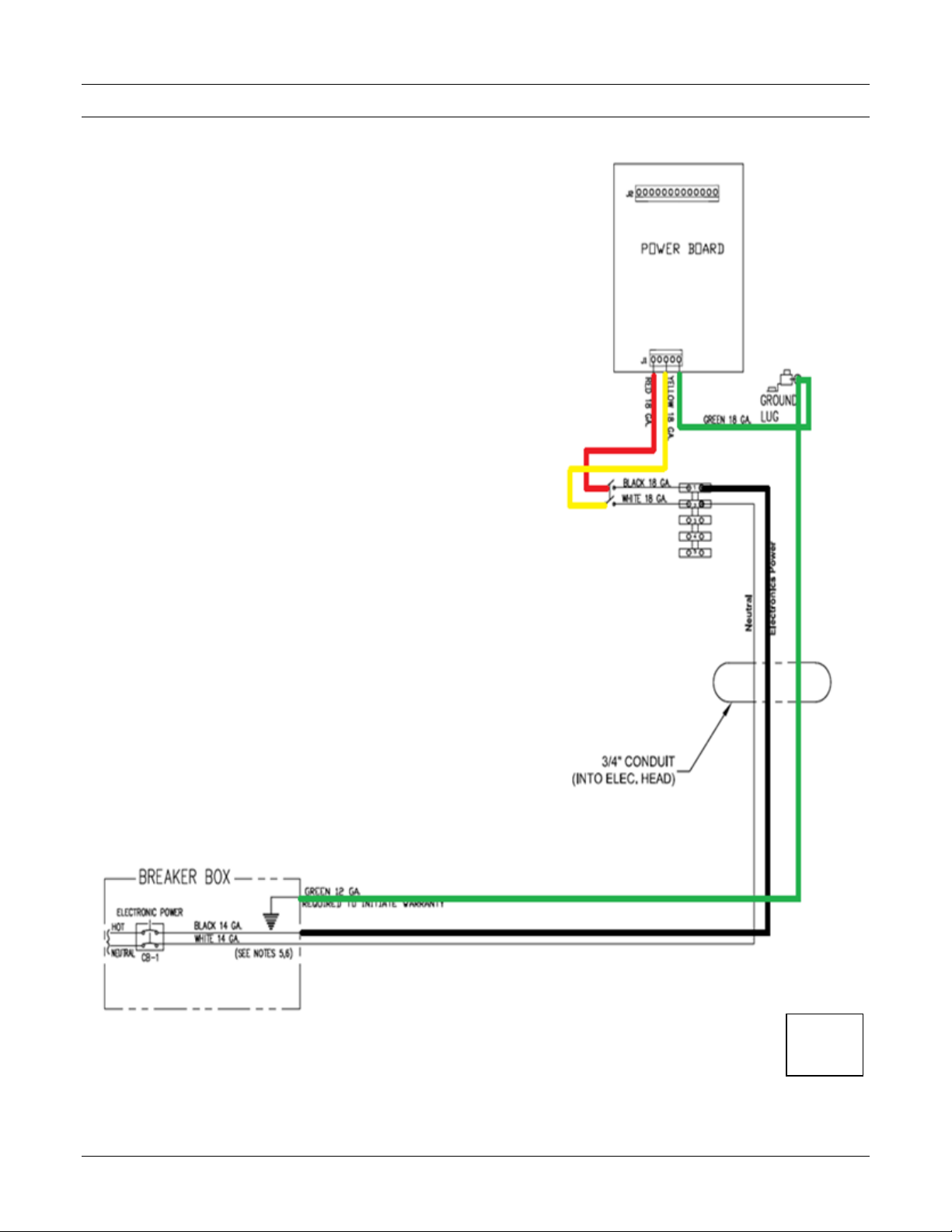
ELECTRICAL RATINGS
Electrical Power ……240 WATTS, 115/120V 50/60hz
P4229
Sheet 1
Rev B
AC POWER CONNECTIONS FOR SITE MASTER SP
Read all safety instructions and notes shown in Figure 1.5 and on wiring diagram 126000-P4229 before applying power to the Site
Master.
NOTES FOR POWER WIRING DIAGRAM
1. All wiring must be installed and used in accordance with the national electrical code
(NFPA #70), Automotive and Marine Service Code NFPA #30), state, and local
electrical codes.
2. All wiring gauge is minimum required, stranded wire with THHN insulation must be
used. Do not reuse old wire from an existing installation.
3. Pull a Green 12 ga. stranded THHN ground wire through the junction box and wiring
through and secure at grounding post near the terminal strip in the Site Master’s
electrical enclosure. Terminate the other end at the main electrical service panel
ground bar. Do not terminate at the neutral bar of a sub-panel or rely on metal
conduit for this ground connection. Each Site Master’s grounding post must be
within 1-ohm resistance to earth ground potential. Do not use wire nuts on ground
circuits, use only compression type connectors. This is required to initiate Bennett’s
Limited Warranty.
4. Use 15 Amp neutral breaking circuit breakers, which are supplied by the customer.
BREAKER IDENTIFICATION:
CB #1 Electronic Power –Hot for electronic power is 115 VAC 50/60 Hz
Note: No more than 2 Site Master’s per breaker.
Figure 0.5 –AC Power Connection
Bennett Site Master Instruction Manual Installation
12
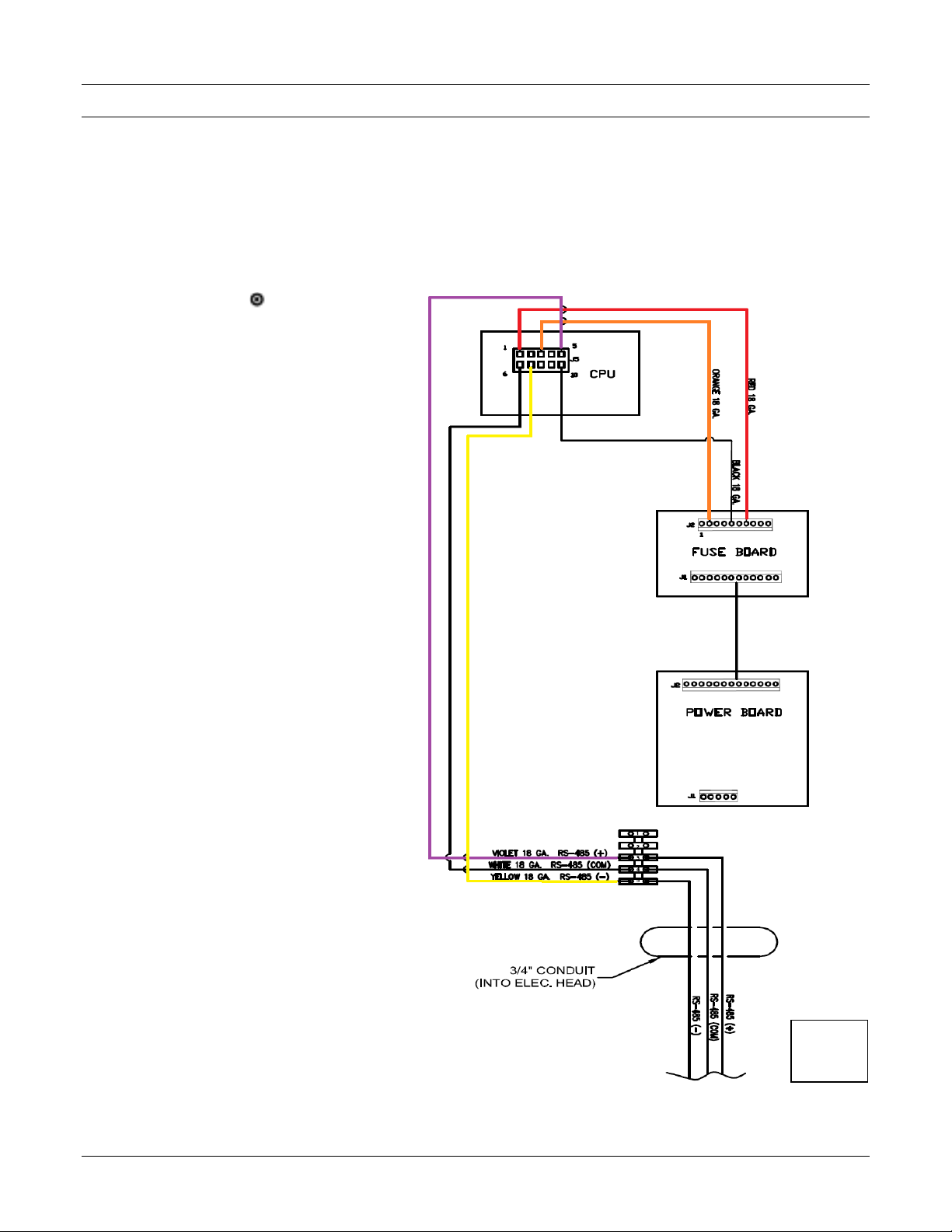
RS-485 COMMUNICATION PROTOCOL FOR SITE MASTER SP
Read all safety instructions and notes shown in Figure 1.6 and on wiring diagram 126000-P4229 before applying power to the Site
Master.
NOTES FOR COMMUNICATION WIRING DIAGRAM
1. All wiring must be installed and used in accordance with the national electrical code (NFPA #70, Automotive and marine service
code NFPA #30A), state, and local electrical codes.
2. All wiring gauge is minimum required, stranded wire with THHN insulation must be used. Do not reuse old wire from an existing
installation.
3. Do not use PVC conduit. Use only rigid metal conduit.
4. Field connection =
Figure 0.6 –RS-485 Communication
P4229
Sheet 2
Rev B
Bennett Site Master Instruction Manual Operation
13
OPERATION
Each Site Master uses one 120V/60Hz circuit for power which is customer supplied by a 15-Amp circuit breaker. AC power is then passed
through a 3-amp fuse to the power board and is converted to DC voltage. DC voltages are then sent throughout the system. Refer to the
descriptions below for more information.
DOOR KEY LOCKS
The Key Locks for the electronic door are located on the right side of the door as shown in Figure 2.1.
1. To lock the electronic door, insert the key in one of the locks and turn clockwise until it stops.
2. Repeat this step for the lower lock on the electronic door.
3. To lock the lower door, turn the key clockwise until it stops in one of the locks.
4. Repeat this step for the other lock.
5. To unlock either door, turn the key counterclockwise until it stops.
POWER SWITCH
WARNING: To prevent electric shock, make sure the current is off at the circuit breaker(s) and the breaker is locked out
before doing any repairs or maintenance to the Site Master.
The power switch is below on the power supply board shown in Figure 2.2, which can be accessed on side 1 of the Site Master, behind
the electronic door. When the switch is in the off position (down), main power is removed from the electronic circuit board.
Service can be performed only on the circuit boards with the switch in the off position. To completely disconnect power from the Site
Master, remove the terminal strip from the Site Master and turn off the main breakers. Read all Safety Instructions prior to removing
power from the Site Master.
ON/OFF Toggle Switch
ON
OFF
Power Supply
Power Toggle Switch
Terminal Strip
Figure 2.1 –Door Key Locks
Figure 2.2 –Power Switch
Bennett Site Master Instruction Manual Operation
14
SSP PAYMENT MODULE
CAUTION: DO NOT REMOVE encrypted PIN Pad or secure card reader from the payment panel. If either
component is removed, activation will be lost and it will become inoperable. It cannot be re-
activated at the site; it must be returned to Bennett Pump for replacement.
The SSP option allows the customer to pay for fuel with a credit card or debit card and receive a receipt. The dispenser is connected to a
financial network through a POS system to allow approval of the cards at the time they are inserted into the dispenser. Refer to the
Simply Secure Payment PCI 3.1 (Large Display w/ SBC2) Programming, Service, and Parts Manual for more information
POWERING UP THE MODULE
The display module receives its power from the power board within the Site Master. There are no power switches on the payment
module. The only way to power the module on or off is by turning the power to the Site Master on or off.
When power is applied to the Site Master, the Bennett Logo will appear for approximately 3 seconds as shown in Figure 2.3.
Note: PLEASE PAY INSIDE will be displayed as shown in Figure 2.4 only if the module and/or POS (Point of Sale) has not been
configured, installed at this time, or communication has been lost.
Refer to 132544 Simply Secure Payment (SSP Large Display w/ SBC2) Programming, Service, and Parts Manual for
Installation, Operation, Programming, and Service information
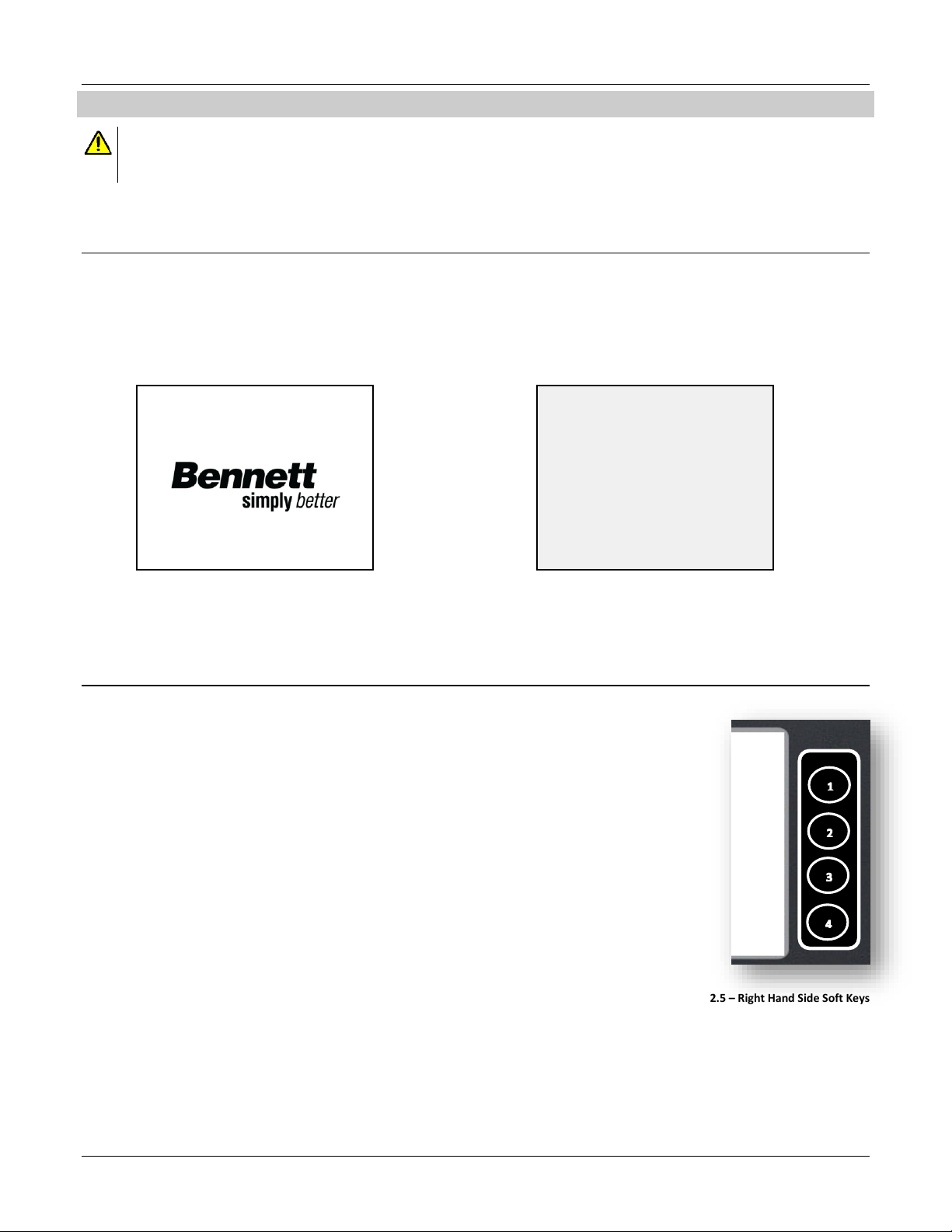
GAINING ACCESS TO MANAGERS MODE
The Soft Keys on the right hand side of the display are the only keys used to enter into Managers Mode. The
top Soft Key on the right is 1 and the bottom Soft Key on the right is 4. The code for entering into Managers
Mode is 122114. Refer to Figure 2.5 for soft key number locations.
Once the correct access code is entered, MANAGER MODE:00 will be displayed at the top of the display. Refer
to the Simply Secure Payment PCI 3.1 (Large Display w/ SBC2) Programming, Service, and Parts Manual for
programming and more information.
PLEASE PAY INSIDE
Figure 2.4 - Non-Configured Module
Figure 2.3- Bennett Logo (Power Up)
Figure 2.5 –Right Hand Side Soft Keys

Bennett Site Master Instruction Manual Maintenance
15
MAINTENANCE
This section provides detailed information about the electronics and electrical components inside the Site Master, which consists of
board specifications, input and output descriptions, wiring connections, and test points if available. The electronics described in this
section control incoming AC power, point of sale communication, data communication, and displays. For information on parts, please
refer to the Parts Section.
The service information in this manual is intended for Bennett trained technicians. All technicians must be aware of all safety instructions
provided on page iii. If you are not a Bennett trained technician, please contact Bennett Technical Support at 1-800-423-6638 for training
information.
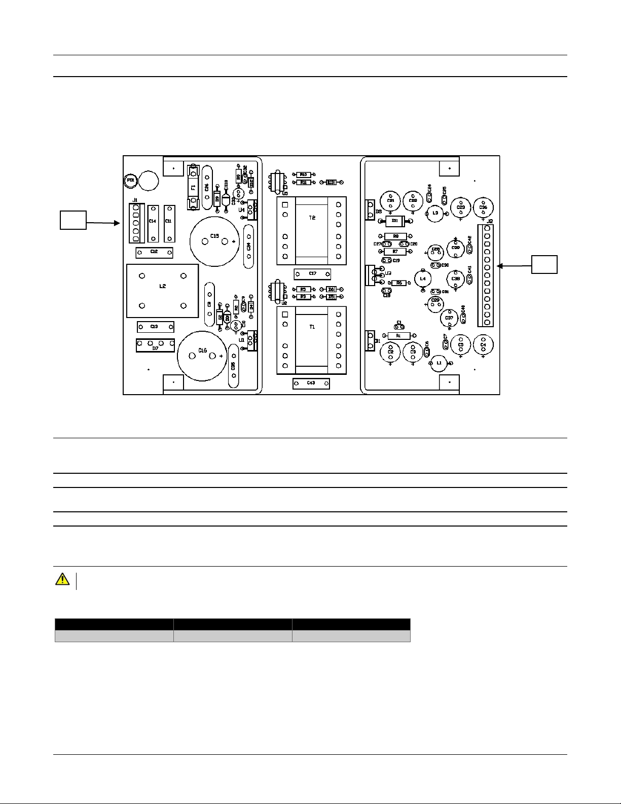
FUSE BOARD (P/N 130809)
Fuses are used to protect the SBC2 Electronics and Power Supply from incoming AC voltage and for power
traveling throughout the system. DC voltages then are sent over to the SBC2 Board through a multi-pin
conductor from connector [J1] of the Power Board to connector [J2] on the SBC2 Board. The standard glass
body fuses are located on a fuse block cartridge as shown in Figure 3.1.
F1 and F2 = +24 Volts
F3 and F4 = +12 Volts
F5 and F6 = +5 Volts
COMPONENT DESCRIPTION
The following is a description of the connections to the terminal strips of all the connections on the fuse board as shown in Figure 3.2.
J1 Power Board
A 12-position header input connects to the power board for +24VDC and +12VDC.
J2 SBC2 Electronics
10-position header input connects to the SBC2 Electronics for Module Power and Module RS-485 Payment Communication.
REPLACING FUSES
CAUTION: Replace fuses only with fuses of the same rating.
If the incoming AC voltage blows a fuse on the power board, check for cross phasing. If a cross-phasing condition exits, correct the
problem before replacing the fuse. Troubleshoot the incoming power prior to replacing the fuse.
Fuse
Part Number
Description
F1, F3, F5
130976
3.15 Amp, Slow
F2, F4, F6
130977
3.0 Amp 5x20, Fast
Figure 3.1 - Fuses
J2
J1
Figure 3.2 - Fuse Board (130809)
Bennett Site Master Instruction Manual Maintenance
16
POWER SUPPLY BOARD (P/N 111209)
The Power Supply Board converts 120-VAC into +12-VDC and +24-VDC. DC voltages operate payment module and its components. The
payment module uses Power comes into the Power Supply assembly on connector [J1]. This power supply creates various DC Voltages for
use throughout the systems.
+24VDC –Card Reader, Display Backlight, and Receipt Printer
+12VDC –Receipt Printer Power, Display
COMPONENT DESCRIPTION
The following is a description of the connections to the terminal strips of all the connections used on the power supply board as shown in
Figure 3.3.
J1 AC Input
A 5-position header is used to receive incoming AC power.
J2 12 VDC and 24 VDC Output
A 13-position header is used to supply +24VDC and +12VDC to the SBC2 CPU. DC voltages are
REPLACING FUSES
CAUTION: Replace fuses only with fuses of the same rating.
If the incoming AC voltage blows a fuse on the power supply board, check for cross phasing. If a cross-phasing condition exits, correct the
problem before replacing the fuse. Troubleshoot the incoming power prior to replacing the fuse.
Fuse
Part Number
Description
F1
110259
3.15 Amp, Slow
Figure 3.3 - Power Supply Board (111209)
J1
J2
Table of contents
Other Bennett Marine Equipment manuals

Bennett
Bennett HIGH FLOW H35 User manual

Bennett
Bennett BOLT Control BCI8000 User manual

Bennett
Bennett H35 Series User manual

Bennett
Bennett LNG Series User manual

Bennett
Bennett 621 User manual

Bennett
Bennett BOLT Rocker BRC4000 User manual

Bennett
Bennett H35 Series User manual

Bennett
Bennett H35 Series User manual


