Bennett H35 Series User manual

H35 Installation Manual
Installation Manual
High Flow H35 Hydrogen Series
Dual Cabinet Configuration
155409 Rev. A 12.20.2023

Important Safety Information
H35 Installation Manual
READ THIS MANUAL
Only Trained Personnel May Work on This Equipment
This manual contains important information for the safe installation of this equipment. Read and
understand this manual before applying power. All service personnel should read this manual before
performing service activities. The material included in this installation manual is accurate at the date of
publication. Failure to follow these instructions could result in bodily injury, damage to the equipment,
or death.
NOTE:Inspect shipped materials for damage or missing equipment. Bennett Pump Company is not liable
for the hazards of transportation. Please address damage claims directly to the delivery company.
NOTE: This device complies with part 15 of the FCC rules. Operation is subject to the following two
conditions: (1) This device may not cause harmful interference, and (2) this device must accept
interference received, including interference that may cause undesired operation.
NOTE: Not all equipment covered in this manual is listed by Underwriters Laboratories.
REV LEVEL
DATE
DESCRIPTION
A
12/20/12023
Release

Table of Contents
H35 Installation Manual TOC-1
1IMPORTANT SAFETY INFORMATION...............1
1.1 SAFETY MESSAGES .........................................1
1.2 CODES AND STANDARDS.................................3
2FEATURES AND SPECIFICATIONS.....................4
2.1 GENERAL INFORMATION.................................4
3SITE PREPARATION .........................................7
3.1 FOUNDATION REQUIREMENTS .........................7
3.2 HAZARDOUS LOCATIONS.................................7
3.3 PIPING FOR HYDROGEN CONNECTIONS..............7
3.4 CONDUIT AND WIRING FOR ELECTRICAL
CONNECTIONS ...........................................................7
4RECEIVE, UNBOX, AND TRANSPORT ...............8
4.1 RECOMMENDED TOOLS AND EQUIPMENT ..........8
4.2 INITIAL INSPECTION CHECKLIST.........................8
4.3 LIFTING AND TRANSPORT INSTRUCTIONS............9
5ANCHORING TO FOUNDATION .....................10
5.1 RECOMMENDED TOOLS AND EQUIPMENT ........10
5.2 INSTALLING ANCHOR BOLTS ..........................10
5.3 LEVELING WITH SHIMS .................................10
6PIPING CONNECTIONS ..................................11
6.1 RECOMMENDED TOOLS AND EQUIPMENT ........11
6.2 CONNECT TO HYDROGEN SUPPLY ...................11
6.3 CONNECT COOLANT SUPPLY AND RETURN.........11
6.4 CONNECT TO HYDROGEN VENT......................11
7ELECTRICAL CONNECTIONS...........................12
7.1 RECOMMENDED TOOLS AND EQUIPMENT ........12
7.2 GROUNDING AND BONDING ..........................12
7.3 CONNECT MAIN DISPENSER TO AUXILIARY CABINET
12
7.4 CONNECT TO STATION COMMUNICATIONS .......12
7.5 CONNECT POSITIVE BATTERY TERMINAL ..........13
7.6 CONNECT TO A/C POWER ............................13
7.7 SEALING CONDUITS IN HAZARDOUS LOCATIONS 14
8POWERING ON AND INITIAL FUNCTIONAL
CHECKS .............................................................15
8.1 RECOMMENDED TOOLS AND EQUIPMENT ........15
8.2 PRE-ACTIVATION CHECKLIST..........................15
8.3 ACTIVATING THE DISPENSER..........................16
8.4 LEAK CHECK WITH INERT GAS ........................17
8.5 PURGING WITH INERT GAS............................17
8.6 LEAK CHECK WITH HYDROGEN GAS.................18
9FINAL INSTALLATION CHECKLIST .................. 19
10 APPENDIX: ABBREVIATIONS AND ACRONYMS
20
TABLE OF CONTENTS

Important Safety Information
H35 Installation Manual 1
1IMPORTANT SAFETY INFORMATION
Please read and understand the following grouped safety messages that contain safety symbols and
safety words. They are defined as:
RED AND WHITE.IF YOU DO NOT FOLLOW THE INSTRUCTIONS, SEVERE INJURY OR DEATH WILL
OCCUR.
Orange and black. If you do not follow the instructions, severe injury or death can occur.
Yellow and Black. If you do not follow the instructions, damage can occur to the dispenser.
White italic NOTICE over blue. Indicates important information that should be observed.
1.1 SAFETY MESSAGES
1. DANGER: THE INSTALLATION SHALL CONFORM TO ALL APPLICABLE LOCAL, REGIONAL, AND
NATIONAL CODES.
2. DANGER: ALL PERSONNEL PERFORMING THE INSTALLATION STEPS OUTLINED IN THIS
MANUAL SHALL BE PROPERLY TRAINED FOR THE TYPE OF WORK ACCORDING TO LOCAL,
REGIONAL, AND NATIONAL CODES.
3. DANGER: ALL PERSONNEL PERFORMING THE INSTALLATION STEPS OUTLINED IN THIS
MANUAL SHALL USE PROPER PPE EQUIPMENT ACCORDING TO LOCAL, REGIONAL, AND
NATIONAL CODES.
4. DANGER: FIRE, EXPLOSION, INJURY, OR DEATH MAY OCCUR IF AN EXPLOSIVE ATMOSPHERE
IS PRESENT AROUND THE EQUIPMENT. DO NOT PERFORM ANY WORK ON THE DISPENSER IF
AN EXPLOSIVE ATMOSPHERE IS PRESENT. NO SOURCES OF IGNITION SHALL BE PRESENT
WITHIN THE HAZARDOUS AREAS AROUND THE EQUIPMENT.
5. DANGER: USE PROPER LIFTING EQUIPMENT RATED TO MORE THAN 2000 POUNDS. STAND
CLEAR WHEN LIFTING AND LOWERING THE DISPENSER

Important Safety Information
H35 Installation Manual 2
6. DANGER: HYDROGEN GAS IS INVISIBLE AND DOES NOT HAVE A DISTINCTIVE ODOR. USE GAS
DETECTORS TO ENSURE NO HYDROGEN IS PRESENT BEFORE PERFORMING THE INSTALLATION
PROCEDURES OUTLINED IN THIS DOCUMENT.
7. DANGER: ALWAYS USE DETECTION EQUIPMENT AS REQUIRED BY LOCAL, REGIONAL, AND
NATIONAL CODES.
8. DANGER: STORAGE AREA TEMPERATURES SHOULD NOT EXCEED 125°F (52°C).
9. DANGER: A MEANS OF OVERPRESSURE PROTECTION SHALL BE PLACED UPSTREAM OF THE
DISPENSER TO RELIEVE AT OR BELOW THE MAXIMUM ALLOWABLE WORKING PRESSURE
(MAWP) OF THE DISPENSER.
10. DANGER: PRESSURE AT THE DISPENSER SHALL NOT EXCEED MAWP DEFINED IN SECTION
2.1.2.
11. DANGER: ALWAYS DEPRESSURIZE THE HYDROGEN SYSTEM BEFORE PERFORMING ANY
ADJUSTMENT OF TUBE CONNECTIONS OR FITTINGS.
12. DANGER: DO NOT EXPOSE THE ELECTRICAL SYSTEM TO WATER.
13. DANGER: THE DISPENSER SHALL BE ELECTRICALLY GROUNDED AS DEFINED IN THIS MANUAL
AND ASSOCIATED TECHNICAL INFORMATION (DRAWINGS, DIAGRAMS, SERVICE BULLETINS,
ETC.) AND AS REQUIRED BY APPLICABLE LOCAL, REGIONAL, AND NATIONAL CODES.
1. WARNING: All electronic covers shall be returned to their designated locations before
powering ON the dispenser.
2. WARNING: When anchoring the dispenser, always level the dispenser with shims before
bolting to the island. Do not shim the middle of the base rails to bolt down the dispenser.
3. WARNING: Electronic components are static sensitive. Personnel performing installation
work on the electronic components shall take appropriate precautions to protect against
static discharge before working on the equipment.
1. CAUTION: Do not drill holes in fuel dispensers. Holes can cause failure of the electronic
equipment. The warranty will become void. Use only adhesive-backed sign mounting
brackets.
2. CAUTION: Before installation make sure that protection against lightning strikes follows
local, state, and national codes.
3. CAUTION: The dispenser system is intended for use with fuel cell grade hydrogen as defined
in Commodity Specification for Hydrogen, CGA G-5.3, and with gas composition at the

Important Safety Information
H35 Installation Manual 3
dispenser nozzle as specified by the Hydrogen Fuel Quality for Fuel Cell Vehicles, SAE 2719,
unless additional precautions are taken.
4. CAUTION: Electrical conduit shall be manufactured and installed according to local, regional,
and national codes.
5. CAUTION: Data wires shall be terminated once at the station and once at the dispenser
according to the wiring diagram. DO NOT splice data wires.
6. CAUTION: Hoses shall be protected from vehicle traffic.
7. CAUTION: All dispenser AC power circuits must be on the same phase or damage will result
to the dispenser 819 power board.
1. Review the DIN sheet for specific dispenser options before starting the installation procedure.
2. Only certified technicians are authorized to service Bennett products and accessories.
3. Incorrect installation will result in degraded performance and will void the limited warranty.
4. The fuel dispenser cabinets are a component of a larger fuel delivery system. For installation
instructions on other parts of the system, refer to the original equipment manufacturer’s
documentation.
5. Read all equipment manufacturer’s installation instructions. Bennett Pump is not responsible
for potential problems involving equipment supplied by other manufacturers.
6. Bennett Pump Company products are designed to meet or exceed the standards of
Underwriters Laboratories, Inc., The Federal Communication Commission, and the National
Institute of Standards and Technology. Compliance with these standards protects the operator
and the consumer from personal injury.
7. Bennett Pump Company will not assume responsibility or liability for any consequential injury
or damage caused by the unauthorized alteration of its products.
1.2 CODES AND STANDARDS
The installation procedure outlined in this document shall be performed according to all local, regional,
and national codes.

Features and Specifications
H35 Installation Manual 4
2FEATURES AND SPECIFICATIONS
Reference the following documents included in the USB package or found on our website at
https://bennettpump.com/resources/manuals/ for further installation guidance.
•P6883, General Overview, H35 HF Main Cabinet
•P6801, Piping and Instrumentation Diagram (P&ID)
•P6921, General Overview, H35 HF Auxiliary Cabinet
•Wire Diagram: P7148 or P7419
•Swagelok Installation Guidelines – Refer to Maintenance Manual 155211.
•Test Procedure Documents – Refer to Maintenance Manual 155211 for the following:
I/O Checks
Zeroing Meter
Gas Detectors
2.1 GENERAL INFORMATION
The Dual-Cabinet Transit dispenser design separates cabinets for electronics and user controls from the
hazardous cabinet housing hydrogen-carrying components and piping. This alleviates the need for extra
gas detection or purging equipment that would be required if the electrical equipment were located
within the hazardous area.
Protection against water ingress has been validated according to the test procedure defined in
CSA/ANSI HGV 4.1:20: Standards for Hydrogen Dispensing Systems (section 6.14).

Features and Specifications
H35 Installation Manual 5
2.1.1 SPECIFICATIONS
Overall Product
Dimensions
Main Dispenser (Hydraulics) 1.7m x 0.813m x 2.38m
Auxiliary Dispenser
(Electronics)
1.59m x 0.813m x 2.47m
Installation Requirements
Anchor dispensers to a concrete foundation with four (4), 1/2” dia. stainless
steel bolts.
Number of Sides 1
Number of Hoses 1
Hydrogen Inlets 1
Heat Exchanger Integrated
Operating Temperature -40⁰C to +50⁰C
Operating Humidity 0% to 95% non-condensing
Displays
(Auxiliary Dispenser)
Total Sale 6-digit LCD
Total Mass 6-digit LCD
Price Per Mass 5-digit LCD
Cabinet Framing Galvanized Steel with UL DTOV2 protective base coat
Metal Covers Painted Cold Rolled or Galvanneal Steel with UL DTOV2 protective base coat
Plastic Covers Painted ABS with UVI Stabilizer
Hydrogen Piping 316 Stainless Steel

Features and Specifications
H35 Installation Manual 6
2.1.2 FLUID AND PROCESS SPECIFICATIONS
Media Gaseous Hydrogen
Temperature Class SAE J2601 T20 (-26⁰C to -17.5⁰C)
Nominal Pressure 35 MPa
MOP at Nozzle 43.8 MPa
MAWP 48.1 MPa
Maximum Inlet Pressure 45 MPa
Test Pressure 52.5 MPa
Maximum Flow Rate* 7.2 kg/min
Connections
(Main Dispenser)
Hydrogen Supply 1” x 9/16” Cone and Thread (Female)
Hydrogen Vent Outlet 1” x 1” Double-Ferrule Tube (Female)
Coolant Supply/Return 2” x 1” Double-Ferrule Tube (Female)
* Maximum flow rate as defined by J2601-2
2.1.3 ELECTRICAL SPECIFICATIONS
Main Supply Voltage
(Auxiliary Dispenser)
230 VAC, 50 Hz
Max Current Draw 1.6 A @ 230 VAC

Site Preparation
H35 Installation Manual 7
3SITE PREPARATION
3.1 FOUNDATION REQUIREMENTS
The dispenser must be mounted on a concrete foundation or a material with an electrical resistance not
exceeding 1 MΩ.
The foundation must be constructed to allow the dispenser to be properly anchored as described in
Section 5.
The foundation must be constructed in accordance with all local, regional, and federal building codes
regarding seismic, wind, and frost conditions.
3.2 HAZARDOUS LOCATIONS
The main cabinet contains the complete hydrogen pressure system which results in a Zone 2 hazardous
area according to the Hazardous Area Drawing. Any equipment not rated for use in a Zone 2 hazardous
area shall be installed outside of the hazardous area. Each piece of instrumentation in the main
dispenser is protected for use in a Zone 2 hazardous area by at least one of the following:
•Intrinsically Safe (Ex ia or ic)
•Non-Sparking (Ex nA)
•Flameproof (Ex db)
•Encapsulation (Ex mb)
The auxiliary cabinet contains electrical equipment not rated for use in any hazardous areas. The
auxiliary cabinet shall not be installed within the hazardous area around the main dispenser or any other
site equipment.
3.3 PIPING FOR HYDROGEN CONNECTIONS
Piping installed for the dispenser’s hydrogen connections shall meet all specifications described in the
footprint drawing and conform to local, regional, and national codes.
3.4 CONDUIT AND WIRING FOR ELECTRICAL CONNECTIONS
The wiring and conduit used for A/C power and communications between the station and dispenser
shall meet all specifications described in the wiring diagram and conform to local, regional, and national
codes.

Receive, Unbox, and Transport
H35 Installation Manual 8
4RECEIVE, UNBOX, AND TRANSPORT
4.1 RECOMMENDED TOOLS AND EQUIPMENT
•Forklift for transporting the crated dispenser.
•Driver to remove screws from the crate.
•Lifting system (hooks, straps, crane, hoist, etc.) as specified in Section 4.3.
4.2 INITIAL INSPECTION CHECKLIST
Before unboxing the dispenser, inspect the crate for visible signs of damage including
shipping indicators shown in Figure 4.1.
Remove the dispenser from the crate and inspect for signs of damage to exterior covers,
displays, and hanging hardware.
Open the upper and lower cabinet doors using the keys that were shipped with the
dispenser and check the following.
Damaged or loose pipes/components/fittings in the hydrogen system.
Damaged, cracked, or loose circuit boards, mounting hardware, and electronic components.
Loose or damaged wire harnesses.
Pump handle harnesses properly connected (behind the nozzle boots).
Figure 4.1: Damage indicator included on a shipping crate.
Note: Any claims related to shipping damage must be filed with the shipping company.
Receive, Unbox, and Transport
H35 Installation Manual 9
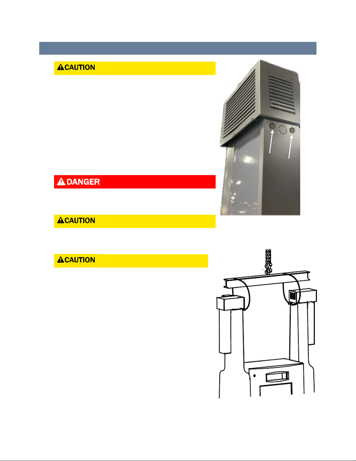
4.3 LIFTING AND TRANSPORT INSTRUCTIONS
DO NOT install the optional valance before lifting.
Refer to Figures 4.2 and 4.3 for lifting specifications.
1. Remove the Phillips Screws (2 each column).
2. Replace with provided 3/8” Eye Bolts.
3. Use a lifting system that is capable of lifting 2000
pounds.
4. Loop user-provided lifting straps through the Eye Bolts.
5. After setting the dispenser replace the Phillips Screws.
USE PROPER PERSONAL BARRIERS TO FENCE OFF THE AREA
AROUND THE UNIT WHILE LIFTING.
The lift strap must be vertical. DO NOT pull upright to the
side.
DO NOT lift the unit by the main hydraulic frame or
vapor barrier, permanent damage will occur.
Figure 4.2. Top of Dispenser
Column.
Figure 4.3. Lifting system sufficient to
lift 2000 pounds.

Anchoring to Foundation
H35 Installation Manual 10
5ANCHORING TO FOUNDATION
5.1 RECOMMENDED TOOLS AND EQUIPMENT
•Concrete anchor bolts, ½” minimum diameter. Material shall be compatible with galvanized
steel.
•Shim stock compatible with galvanized steel.
•Wrench set for installing anchor bolts.
5.2 INSTALLING ANCHOR BOLTS
•The dispenser shall be secured to the foundation using the (4) anchor points specified in the
Footprint Diagram.
•Anchor bolts used must meet the specifications listed in Section 5.1 and conform to all
applicable local, regional, and national standards.
5.3 LEVELING WITH SHIMS
The dispenser shall be leveled using the shim stock as specified in Section 5.1. Shims are to be placed as
close to anchor bolts as possible and shall not be installed in the middle of the base rail.

Piping Connections
H35 Installation Manual 11
6PIPING CONNECTIONS
Piping from the station shall be available at the dispenser site. Piping specifications and locations of the
connections are specified in the footprint drawing.
6.1 RECOMMENDED TOOLS AND EQUIPMENT
•Wrench set for installing pipe fittings
•Torque wrench to tighten Cone and Thread fittings to proper torque specification
•Swagelok Inspection Gauge for checking double-ferrule connections.
6.2 CONNECT TO HYDROGEN SUPPLY
•Hydrogen shall be supplied to the dispenser by a medium-pressure piping system.
•The dispenser includes a female cone and thread fitting for connecting to the station tubing.
•The size and position of the female cone fitting are specified in the footprint drawing.
6.3 CONNECT COOLANT SUPPLY AND RETURN
•Connect coolant supply and return. Unless this dispenser doesn’t have a heat exchanger.
6.4 CONNECT TO HYDROGEN VENT
The dispenser will require a connection to a vent outlet to allow for depressurization of the nozzle after
each fill, and depressurization of the entire system for service. The dispenser includes a double ferrule
fitting for connecting to the station tubing. The size and position of this fitting are specified in the
footprint drawing.
Bennett recommends the use of Swagelok hardware for double-ferrule connections; however, hardware
from alternative manufacturers is permitted only if it meets the specifications listed in the footprint
drawing. Refer to the fitting manufacturer’s instructions for specifications.

Electrical Connections
H35 Installation Manual 12
7ELECTRICAL CONNECTIONS
Electrical connections need to be installed to provide protective earth grounding, power to the
dispenser, and communications with the station. Required wire gauges, colors, and terminations are
specified in the wiring diagram.
7.1 RECOMMENDED TOOLS AND EQUIPMENT
•Multimeter
•Electrical Conduit and Fittings
•Potting Compound for sealing conduit fittings
•Conduit Sealant
•Wire Separator
7.2 GROUNDING AND BONDING
Pull the ground (PE) wire through the conduit from the breaker box. Terminate one end on the breaker
box ground bar and the other end to the dispenser ground terminal as indicated on the wiring diagram.
7.3 CONNECT MAIN DISPENSER TO AUXILIARY CABINET
The Auxiliary cabinet will come from the factory with all cables pre-wired and coiled inside the upper
enclosure. Pull the unconnected ends of each cable through the underground conduit and terminate the
cables to the main dispenser junction boxes according to the wiring diagram.
7.4 CONNECT TO STATION COMMUNICATIONS
Pull communication wires from the station through the conduit and terminate in the dispenser as
indicated on the wiring diagram.

Electrical Connections
H35 Installation Manual 13
7.5 CONNECT POSITIVE BATTERY TERMINAL
The 12-volt battery ships from the factory disconnected. The dispenser has a wire harness that connects
the battery terminals to J2 on the 819 Power Board.
Connect the wire harness to the positive (red) and negative (black) terminals of the battery. Verify the
other end of the harness is securely connected to J2 on the 819 Power Board.
7.6 CONNECT TO A/C POWER
Pull power wires from the on-site breaker box through the conduit and terminate on the dispenser 819
Power Board as indicated on the wiring diagram.
12 VDC
Battery
Figure 8.1. Illustrated plan view of
battery connections.

Electrical Connections
H35 Installation Manual 14
7.7 SEALING CONDUITS IN HAZARDOUS LOCATIONS
Electrical conduits located in hazardous areas shall be sealed to prevent hydrogen gas from entering the
conduit and moving to an unclassified space. Sealing material and installation shall conform to all local,
regional, and national codes.
7.7.1 INSTALLING THE WIRE SEPARATOR
1. Fit wires through the wire separator.
No more than 13 wires can be installed in a wire
separator. If the installation requires more than 13
wires, a second inlet of conduit and wire separator is
required.
2. Hold the previously installed wire separator out of
the way and Wrap Chico X fiber around the wires.
Push into conduit assembly to prevent potting from
running down the length of the conduit, see Figure
8.2.
Note: Use Chico A05 potting compound for sealing fittings in hazardous locations.
3. Push the wire separator at least ¾ inch (1.90 cm) into the conduit.
4. Prepare the potting compound according to the product directions.
5. Using a funnel, pour potting into the conduit, be sure to get potting in between each wire.
6. Let stand until firm.
Figure 8.2. Wiring Installation

Powering ON and Initial Functional Checks
H35 Installation Manual 15
8POWERING ON AND INITIAL FUNCTIONAL CHECKS
8.1 RECOMMENDED TOOLS AND EQUIPMENT
•Multimeter
•Portable hydrogen gas detector for each person working on equipment
8.2 PRE-ACTIVATION CHECKLIST
All (4) anchor bolts are installed and torqued to specification.
Circuit boards are undamaged and remain securely fastened in place.
No visible damage to cables or wire sheathing.
Cables and wires remain securely connected.
Cables and wires are correctly terminated according to the wiring diagram.
Both battery leads are connected.
Ground (PE) wire is securely terminated on the dispenser ground bar.
Resistance between Nozzle/GND terminal is < 1Ω
Electrical resistance between the ground screw and the earth ground measures <= 1Ω
The dispenser hydrogen system is depressurized, and the inlet valve is fully closed.
All electrical conduits are potted.
Correct circuit breaker installed in site electrical cabinet.
The power switch on the 819 Power Board is in the OFF position.
Vibration switch is not tripped.
Verify that no hazardous atmosphere exists at the dispenser site.

Powering ON and Initial Functional Checks
H35 Installation Manual 16
8.3 ACTIVATING THE DISPENSER
After completing the Pre-Activation Checklist in Section 8.2, turn ON the breaker that supplies power to
the dispenser and follow these steps to activate it:
1. Verify that no hazardous atmosphere exists at the dispenser site.
2. Verify the terminals on the 819 Power Board are energized to the expected voltage according
to the wiring diagram.
3. With the power switch OFF, electrical power should not be present anywhere in the system
after the 120VDC terminals on the 819 Power Board.
IF ANY SIGNS OF POWER (LIGHTS, SOUNDS, VOLTAGE READINGS, ETC.) ARE OBSERVED IN THE
ELECTRONIC CABINET WITH THE POWER SWITCH IN THE OFF POSITION, STOP AND CONTACT
BENNETT TECHNICAL SUPPORT.
4. At the 819 Power Board, toggle the power switch to the ON position.
5. Check and verify each item in Section 8.3.1 Activation Checklist.
Verify the gas detector display is illuminated and does not indicate the presence of hydrogen
gas.
IF A GAS DETECTOR IS DETECTING HYDROGEN GAS, STOP AND FOLLOW THE PROCEDURE AS
DEFINED BY THE APPROPRIATE SITE SAFETY PROTOCOLS. DO NOT PROCEED WITH
INSTALLATION UNTIL THE SOURCE OF RELEASE HAS BEEN IDENTIFIED AND SHUT OFF.
8.3.1 ACTIVATION CHECKLIST
LEDs on PLC I/O cards are all green.
TX/RX LEDs are illuminated on the serial module.
Door panel displays are illuminated and showing correct splash screens.
The latest software revision is shown on the main display and payment screens.
Circuit boards on the door panel are receiving power.
24 VDC power supply is ON.
LEDs on safety relays are not illuminated.
IRDI Converter is receiving power.
PLC display is illuminated and does not indicate any faults.

Powering ON and Initial Functional Checks
H35 Installation Manual 17
Meter transmitter display is illuminated and does not indicate any faults.
Thermocouple PR display is illuminated and shows the correct information.
Once all items in the checklist above have been completed, lift and lower the nozzle handle twice to
clear the e-stop message.
8.4 LEAK CHECK WITH INERT GAS
Perform a leak check on the dispenser by pressurizing it with an inert gas (generally nitrogen, helium, or
nitrogen-helium mix) and monitor for any leaks. Pressure should be set to MOP. Maintain pressure for a
minimum of 10 minutes.
BEFORE PRESSURIZING THE SYSTEM, REVIEW P&ID AND MAKE SURE THAT ANY
COMPONENTS OR TUBING THAT ARE NOT RATED TO TEST PRESSURE ARE ISOLATED FROM
THE PRESSURE SOURCE OR OPEN TO THE ATMOSPHERE.
8.5 PURGING WITH INERT GAS
The hydrogen system shall be purged with an inert gas before hydrogen can be introduced. Refer to the
ASME B31.12 standard for purging the dispenser. The steps below represent an example purging
procedure.
1. Connect the nozzle to a purge apparatus that will provide a path to vent or a hydrogen
recapture system.
2. Lift the lever to the “fueling” position.
3. Use the Hydrogen Dispenser Service Software to open FCV-100, FV-100, and SV-102.
4. With the outlet of the purge apparatus closed, pressurize the dispenser with inert gas to
approximately 5% MAWP.
5. Open the outlet of the purge apparatus, allowing the gas to flow through the dispenser.
6. Monitor pressure while purge gas is flowing through the system.
7. When flow begins dying off, close the outlet of the purge apparatus. Do not allow pressure to
drop completely to zero or contaminants may be reintroduced into the system.
8. Repeat these steps as many times as needed to ensure the system has been completely purged
of any contaminants.
Other manuals for H35 Series
2
Table of contents
Other Bennett Marine Equipment manuals

Bennett
Bennett SITE MASTER EMV User manual

Bennett
Bennett H35 Series User manual

Bennett
Bennett BOLT Control BCI8000 User manual

Bennett
Bennett 621 User manual

Bennett
Bennett LNG Series User manual

Bennett
Bennett BOLT Rocker BRC4000 User manual

Bennett
Bennett HIGH FLOW H35 User manual

Bennett
Bennett H35 Series User manual


