Benning LD 60 User manual

BENNING LD 60 – Quick reference guide
http://tms.benning.de/ld40-ld60 1 5246 09/2022 en
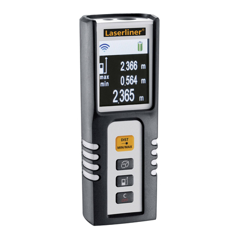
Laser distance meter BENNING LD 60
Contamination level: 2
Measuring range: 0.05 … 60 m
Battery life (alkaline batteries):
up to 10 000 measurements
Protection category: IP 54
Measuring speed: 2 measurements per second
Laser type: 650 nm, Class II, <1 mW
Housing dimensions (length x width x height): 105 mm x
48 mm x 21 mm
Operating temperature: -5 … 40 °C
Measuring accuracy: ±1.5 mm
Ambient temperature (storage): -20 … 60 °C
Laser dot size: 25 mm at a distance of 30 m
Weight (batteries included): 83.7 g
Max. relative air humidity: 85 % RH
- Only use the device within the framework of the corresponding technical data.
- Target group: Professional users, craftspeople and do-it-yourselfers
- Basic knowledge required: Knowledge of testing and measuring equipment as well as basic knowledge of length measurement, area and volume calculation as well as trigonometric functions
- The device may only be used in a technically perfect and safe condition. Always check the device for damages before using it.
- Observe relevant regulations on occupational safety and health as well as those on environmental protection.
- Use the device only in dry environments and not in potentially explosive environments.
- Operation with 2 1.5 V micro batteries (AAA)
- Please find the operating manual of the device at http://tms.benning.de/ld40-ld60
WARNING
WARNING
Laser beam
Eye damage or risk of accident due to glare are possible in case of eye contact with the laser beam.
•Never look directly into a laser beam or its reflections!
•If the laser beam hits your eye, close your eyes and immediately turn your face away from the laser beam.
Normally, eyes close automatically due to the blink reflex and aversion responses take place.
•Do not point the laser beam at persons or animals.
•Do not leave the unit switched on unnecessarily.
Opening the device
Eye damage or risk of accident due to glare are possible in
case of eye contact with the laser beam when opening the
device.
•Do not open the device (except for the battery
compartment).
•Please contact your specialty retailer or the returns
management for any repairs.
Operation
- Switching the device ON: / , Switching the device OFF: >2 seconds
- Opening the menu:
- Menu navigation:
Left / Right / Confirm / Back
- Starting measurement:
- Please note that for many of the measuring functions, the respective function of the keys is
shown on the digital display.
- Changing the reference plane: (the set reference plane is shown in the respective
symbol on the digital display)
- Offset of protective rubber holster: >2 seconds
(A green frame at the respective symbol on the digital display shows that the protective
rubber holster has been factored.)
- Please note that for many of the measuring functions, the length to be measured or the
measured value determined and displayed is indicated on the digital display by the
respective part of the measuring function symbol flashing.
Measurements and functions
Requirements for measuring
- Please consider the brightness of the surrounding light conditions:
•The ambient light must not be too bright.
•Avoid measuring in direct sunlight.
- Avoid measuring towards reflective, transparent or very porous surfaces.
- Make sure that the laser beam outlet and the receiving lens are not covered.
- Make sure that the device does not move during the measurement (exception: continuous
measurement).
- Select the reference plane according to the application.
- Select the desired measurement or calculation from the menu.
Length measurement (single measurement)
The length measurement (single measurement) is intended for
measuring a distance between the device and an opposite
surface. After being switched on, the device is automatically in
this measuring function.
1. Point the laser beam at the measuring point (A).
2. Press the “Measurement” key.
The measurement is started and the measured value will be
shown on the digital display.
Length measurement (continuous measurement)
Length measurement (continuous measurement) is intended for
continuously measuring a changing distance. In addition to the
currently measured distance, the shortest and the longest
measured distance of the measurement series are shown on the
digital display.
1. Point the laser beam at the measuring point.
The measured value will be shown on the digital display and
updated when the distance changes.
Area calculation
The area calculation function is intended for determining the area
of a rectangular surface by measuring two measured lengths that
are perpendicular to each other.
1. Point the laser beam at the first measuring point (A).
2. Press the “Measurement” key.
The measurement is started and the measured value (L) will
be shown on the digital display.
3. Point the laser beam at the second measuring point (B).
4. Press the “Measurement” key.
The measurement is started and the measured value (W) will
be shown on the digital display.
The device calculates the area from the two measurements and the determined value will
be shown on the digital display.
Volume calculation
The volume calculation function is intended for determining the
volume of a rectangular space by measuring three measured
lengths that are perpendicular to each other.
1. Point the laser beam at the first measuring point (A).
2. Press the “Measurement” key.
The measurement is started and the measured value (L) will
be shown on the digital display.
3. Point the laser beam at the second measuring point (B).
4. Press the “Measurement” key.
The measurement is started and the measured value (W) will
be shown on the digital display.
5. Point the laser beam at the third measuring point (C).
6. Press the “Measurement” key.
The measurement is started and the measured value (H) will be shown on the digital
display. The device calculates the volume from the three measurements and the
determined value will be shown on the digital display.

BENNING LD 60 – Quick reference guide
http://tms.benning.de/ld40-ld60 25246 09/2022 en
Indirect length calculation
The indirect length calculation is intended for determining certain distances using length
measurements to various points and angle measurements of the respective axes.
Indirect length calculation 1
1. Point the laser beam at the first measuring point (A).
2. Press the “Measurement” key.
The measurement is started and the measured value will be
shown on the digital display.
3. Point the laser beam perpendicularly to the surface at the
second measuring point (B).
4. Press the “Measurement” key.
The measurement is started and the second measured value
will be shown on the digital display.
The device calculates the distance between the two
measuring points from the measurements and the determined
value will be shown on the digital display.
/ Indirect length calculation 2 / 3
1. Point the laser beam at the
first measuring point (A).
2. Press the “Measurement”
key.
The measurement is started
and the measured value will
be shown on the digital
display.
3. Point the laser beam at the
second measuring point (B).
4. Press the “Measurement”
key.
The measurement is started and the second measured value will be shown on the digital
display.
5. Point the laser beam perpendicularly to the surface at the third measuring point (C).
6. Press the “Measurement” key.
The measurement is started and the third measured value will be shown on the digital
display. The device calculates the distance between the measuring points A and B from the
measurements and the determined value will be shown on the digital display.
Indirect length calculation 4
1. Point the laser beam at the measuring point (A).
2. Press the “Measurement” key.
The length measurement and angle measurement (in relation
to the horizontal) are started and the measured values will be
shown on the digital display. The device calculates the
distance between measuring point A and the horizontal
perpendicular (with respect to the distance to be calculated)
from the measurements. The determined value will be shown
on the digital display.
/ Indirect length calculation 5 / 6
1. Point the laser beam at the
first measuring point (A,
above the horizontal
perpendicular with respect to
the distance to be
calculated).
2. Press the “Measurement”
key.
The length measurement and angle measurement (in relation to the horizontal) are started
and the measured value for the length will be shown on the digital display.
3. Point the laser beam at the second measuring point (B, indirect length calculation 5: below
the horizontal perpendicular, indirect length calculation 6: above the horizontal
perpendicular with respect to the distance to be calculated).
4. Press the “Measurement” key.
The length measurement and angle measurement (in relation to the horizontal) are started
and the measured values (angle between measuring points A and B) will be shown on the
digital display. The device calculates the distance between the measuring points A and B
from the measurements and the determined value will be shown on the digital display.
Digital spirit level (axis)
The digital spirit level (axis) is intended for measuring an angle of
an axis in relation to the horizontal and for displaying the
corresponding inclination.
1. Place the device flat onto the surface to be checked.
2. Align the device. The axis of the device must correspond to
the axis to be checked.
The measured value will be shown on the digital display and a
digital spirit level indicates the inclination.
In horizontal position, the alignment point (“bubble”) is exactly
between the two markings and will be displayed in green.
Digital spirit level (surface)
The digital spirit level (surface) is intended for displaying an inclination of a surface in relation
to the horizontal.
1. Place the device onto the surface to be checked.
The digital spirit level indicates the inclination. In horizontal position, the alignment point
(“bubble”) is exactly within the inner marking and will be displayed in green.
Stake-out function
The stake-out function is intended for dividing a distance into
previously set subsections of equal lengths.
1. Set the desired length of the subsections.
2. Press the “Measurement” key.
3. Point the laser beam at the measuring point.
4. Press the “Measurement” key.
The measurement is started and the following values will be
shown on the digital display:
- Set length of the subsections (setting)
- Number of subsections with respect to the measured
distance (measured value)
- Measured distance (measured value)
- Yellow arrows on the top and bottom of the digital display: display in which direction the
next complete subsection is located (integer).
5. Reposition the device accordingly.
Press the “Measurement” key to interrupt the measurement and press the “Menu” key to
exit the measuring function.
Measuring units
Metre
Centimetre
Millimetre
Foot
Inch
Length
m
cm
mm
ft
in
Area
m²
m²
m²
ft²
ft²
Volume
m³
m³
m³
ft³
ft³
Settings
- Key tones (volume / OFF)
- Automatic rotation of the digital display ON / OFF
- Opening the measured value memory / deletion via
- Calibrating the spirit level (observe operating manual!)
Further measuring functions
For more detailed information or for information on further measuring functions (e. g.
calibration of the spirit level, measured value memory, addition / subtraction of measured
values), please refer to the operating manual on the Internet at
http://tms.benning.de/ld40-ld60 .
Error messages
Code
Description
Remedial measure
Err01
Measured value outside
measuring range
Carry out the measurement within the
measuring range.
Err02 Reflected signal too weak Carry out the measurement at a measuring
point with a different surface.
Err03
Measured value outside of
display range (max. 99 999)
Divide the measurement into smaller
subsections.
Err04
Pythagoras calculation failed
Check whether the measured values are
correct and the correct measuring sequence
has been observed.
Err05
Low battery
Replace the batteries of the device.
Err06
Ambient temperature
outside the operating
temperature
Carry out the measurement at a permissible
ambient temperature.
Err07
Ambient light too bright
Carry out the measurement in a darker
environment.
Disposal and environmental protection
At the end of product life, dispose of the unserviceable device and the batteries via
appropriate collecting facilities provided in your community.
Other manuals for LD 60
1
Popular Analytical Instrument manuals by other brands

Titan
Titan TTS-TJ Series user manual
Aquaread
Aquaread Aquaprobe AP-700 instruction manual
Parkside
Parkside PLEM 20 A1 Operation and safety notes
VOLTCRAFT
VOLTCRAFT BS-500 operating instructions
Spartan
Spartan Mini Cam Owner's instruction manual
Maxtec
Maxtec MaxO2 OM-25A Operating manual & instructions for use
