BenQ S80 Setup guide

Release 1.0
Technical Documentation 10/2005
TD_Repair_L2.5L_S80_R1.0.pdf Page 1 of 18
Service Repair Documentation
Level 3 (basic)
S80/82/SFG75
Release Date Department Notes to change
R 1.0 22.12.2005 BenQ CC S CES New document
Company Confidential
2005©BenQ

Release 1.0
Technical Documentation 10/2005
TD_Repair_L2.5L_S80_R1.0.pdf Page 2 of 18
Table of Content
1Introduction ...............................................................................................................................3
1.1 PURPOSE ...............................................................................................................................3
1.2 SCOPE ...................................................................................................................................3
1.3 TERMS AND ABBREVIATIONS ...................................................................................................3
2List of available level 3 basic parts..........................................................................................4
3Hardware requirements ............................................................................................................4
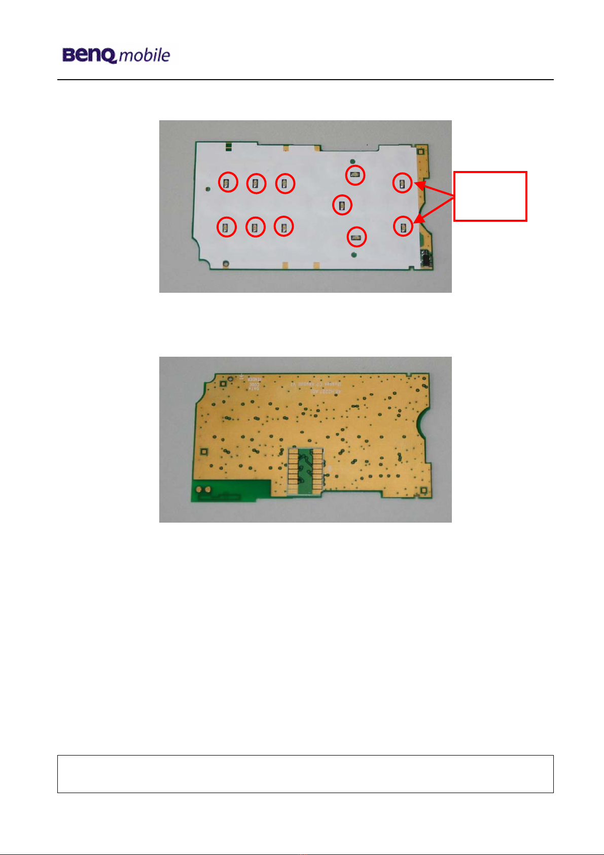
4S80 Board layout.......................................................................................................................5
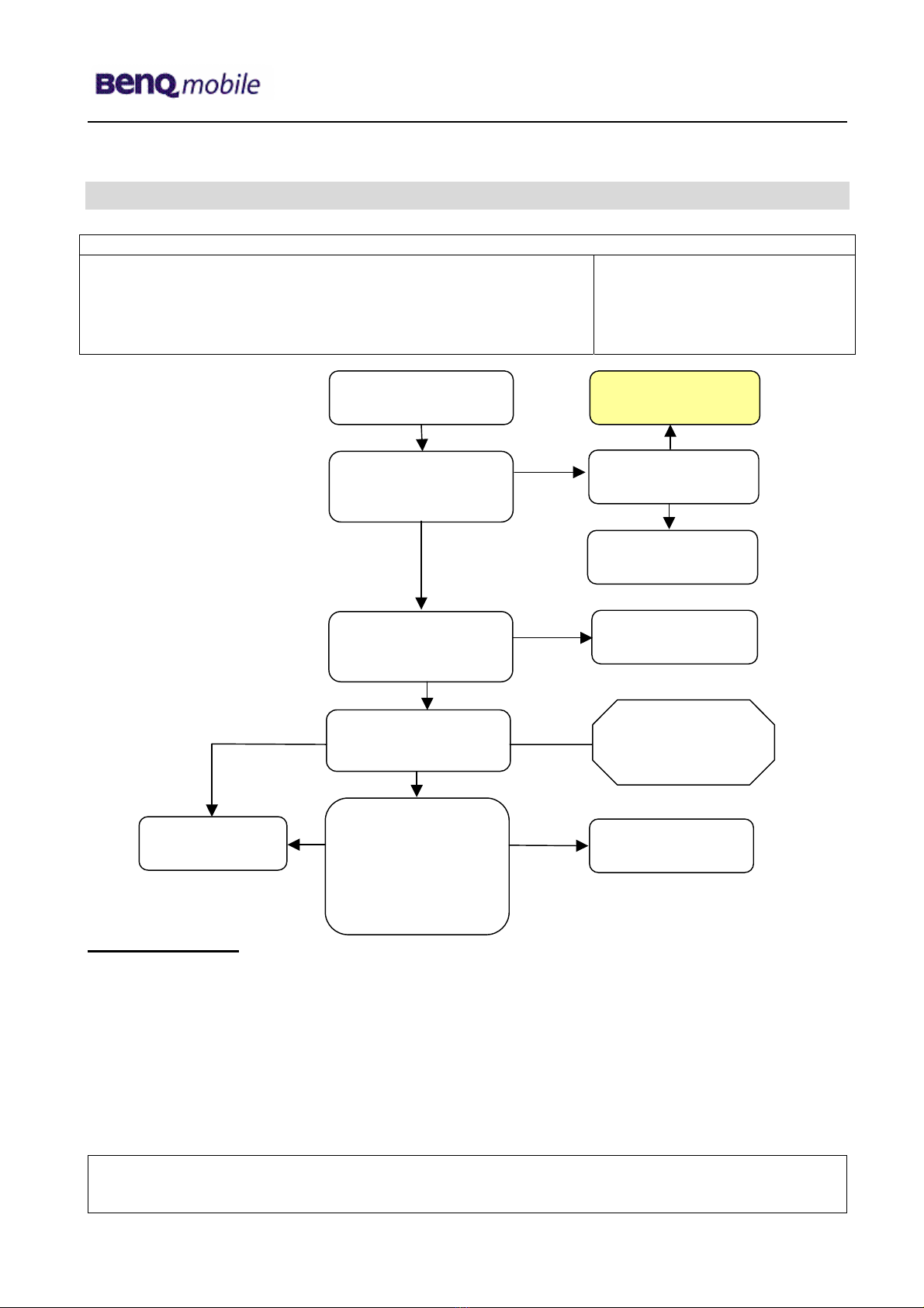
5SIM Card Problems ...................................................................................................................7
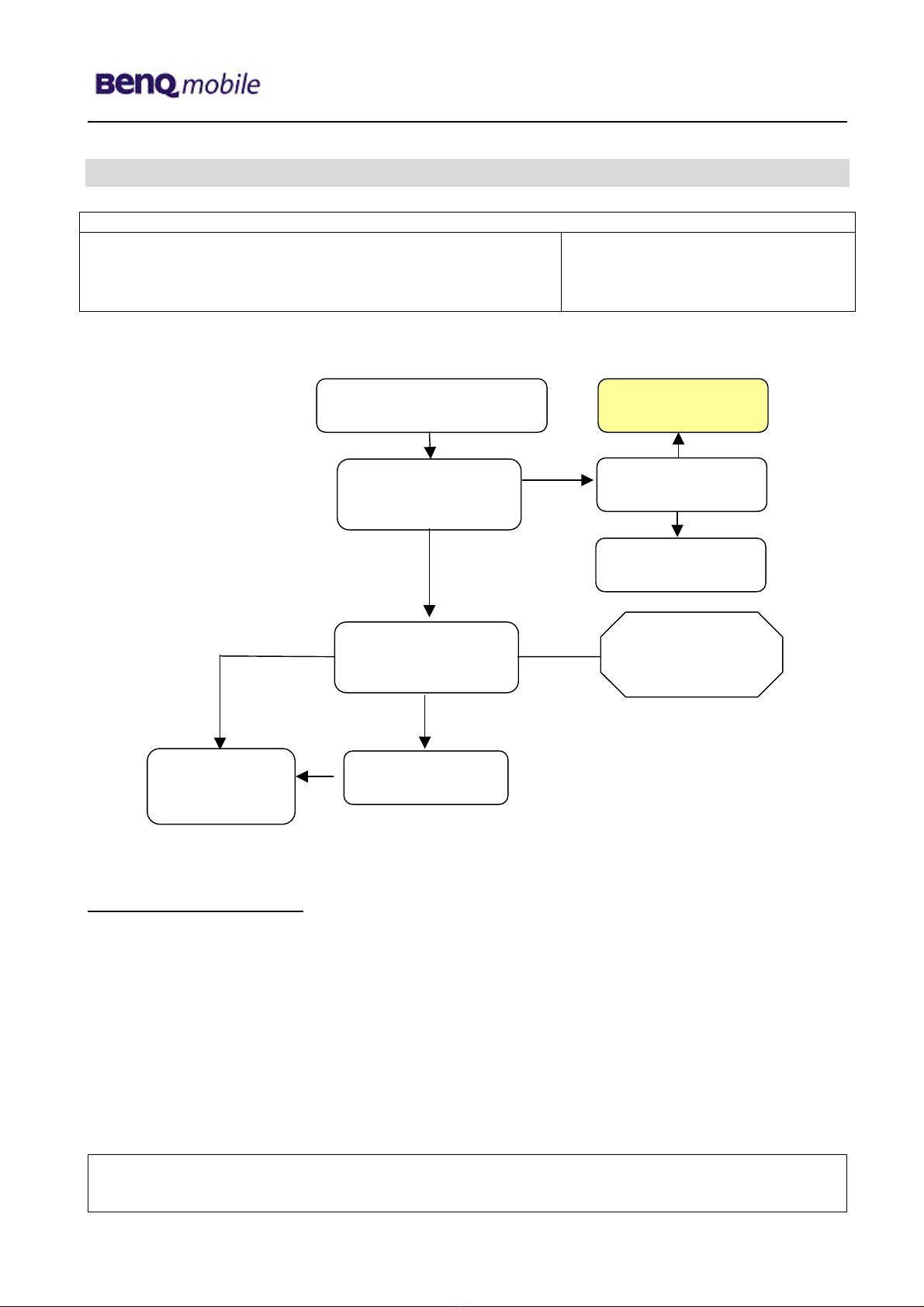
6IO Connector Problems ............................................................................................................8
7B to B connector (upper slider part) problems.....................................................................10
8Main keypad illumination problems.......................................................................................11
9Connector Battery...................................................................................................................12
10 Connector RF Internal Antenna .............................................................................................13
11 Connector Mini SD ..................................................................................................................14
12 Connector Vibra ......................................................................................................................15
13 Fuse..........................................................................................................................................16
14 Connector Sidekeys................................................................................................................17
15 Connector MMI ........................................................................................................................18
Company Confidential
2005©BenQ

Release 1.0
Technical Documentation 10/2005
TD_Repair_L2.5L_S80_R1.0.pdf Page 3 of 18
1 Introduction
This document describes the performance description for Siemens service partners.
1.1 Purpose
This Service Repair Documentation is intended to carry out repairs on BenQ Mobile repair level 3
basic. The described failures shall be repaired in Siemens authorized local workshops only,
The level 3(former Level 2.5e) partners are obliged to repair level 2 classified boards, up to their
repair level, under consideration of the information given by level 3 repair instruction.
All repairs have to be carried out in an ESD protected environment and with ESD protected
equipment/tools. For all activities the international ESD regulations have to be considered.
Assembling/disassembling has to be done according to the latest S80 Level 2 repair documentation.
It has to be ensured that every repaired mobile Phone is checked according to the latest released
General Test Instruction document (both documents are available in the Technical Support section
of the C-market).
Check at least weekly C-market for updates and consider all S80 related Customer Care Information
S80 Part number on IMEI label:
Scrap Handling: All Scrap information given in this manual are related to the
SCRAP-Rules and instructions.
Attention: Consider the new "LEAD-FREE" soldering rules (available in the communication
market), avoid excessive heat.
1.2 Scope
This document is the reference document for all BenQ mobile authorised Service Partners which are
released to repair BenQ mobile phones up to level 2.5 light.
1.3 Terms and Abbreviations
Company Confidential
2005©BenQ

Release 1.0
Technical Documentation 10/2005
TD_Repair_L2.5L_S80_R1.0.pdf Page 4 of 18
2 List of available level 3 basic parts
(According to Component Matrix V1.11 - check C-market for updates)
Product ID Order Number Description CM
S80 J200 L50334-Z97-C522
CONNECT SKT60P AXK7L60227
BQ20.L1096.060
S80 U800 L50851-Z1901-A62 ANT 3*5.1*5 56E12 BQ20.M0007.021
S80 J302 L50334-Z97-C523
CONNECTOR DC PWR 2P
BQ20.N2002.021
S80 J301 L50334-Z97-C524
CON BATT3P CBE-4517-2904H
BQ21.N0036.011
S80 U852 L50334-Z97-C525
CONN SPRING SBS23-2K30F00
BQ21.N0045.011
S80 J250 L50334-Z97-C526
CONN I/O 10P ACT/916-2941
BQ2K.N0083.001
S80 J351 L50334-Z97-C527
CONN SIM 6P D2.54 302-368
BQ21.N0050.001
S80 J350 L50334-Z97-C528
CONN MINI SD 9P 500525
BQ21.N0058.011
S80 J201 L50334-Z97-C529 CONN BTB D1.5 18P BQ21.N1003.011
S80 J202 L50315-Z77-C261 SWI VOLUME KEY 5P BQ21.P0004.005
S80 J300 L50158-A185-A16-1
ASS LOUD SPEAK. CONN.
S80_BQ60.H0916.001
S80 J251 L50158-A185-A17-1
ASSY CONN. MIC WHITE
S80_BQ65.G0101.004
S80 MMI
board L50840-L2133-D670 DISDIODE LED BL-HB536G
BQ83.00536.071
S80 MMI
board L50810-U6228-D670 IC PER HALL A3212ELH BQ74.03212.09Y
S80 F250
F300 L50145-A820-Y23 FUSE 1A 24V F0603 1608FF
BQ69.41004.001
S80 U801 L50145-K280-Y415
SWITCH ANT MS-147 HIROSE
BQ69.50017.001
S80 L50851-Z1901-A63
ANT 2.4GHz AT5020-B2R8HAA
BQ69.F0005.021
3 Hardware requirements
(According to General soldering information V1.3 - check C-market for updates)
Jigs, Tools and working materials for all described repairs:
hot air blower
soldering gun
tweezers
flux
solder
Company Confidential
2005©BenQ

Release 1.0
Technical Documentation 10/2005
TD_Repair_L2.5L_S80_R1.0.pdf Page 5 of 18
4 S80 Board layout
Upper board side
Lower board side
J350:
Mini SD
Connector
J250:
IO Connector
J302:
Connector
DC Power
J201
MMI
Connector
J251:
Micro
p
hone
J200:
Connector
BTB
J351:
SIM Card
U801:
Antenna
Switch
Switch
volume Keys
J301:
Battery
Connector
U800:
Antenna
Contact
Fuse 1A
U852:
Bluetooth
Antenna
Contact
J300:
Vibra Contact
Company Confidential
2005©BenQ

Release 1.0
Technical Documentation 10/2005
TD_Repair_L2.5L_S80_R1.0.pdf Page 6 of 18
MMI Board
Disdiode
Company Confidential
2005©BenQ

Release 1.0
Technical Documentation 10/2005
TD_Repair_L2.5L_S80_R1.0.pdf Page 7 of 18
5 SIM Card Problems
Fault Symptoms
Customer: GRT:
Handset does not accept SIM card SIM Card Problems
SIM Card Problems
Watch for oxidation and
damaged pads of the
SIM Card reader
Caused by customer
SCRAP - has to be send
separately to WSC
Okay Not
oka
y
Check the status of the
EMI Filter visually
Check the status of the
SIM Card reader visually
Use the resistor test
function of a multimeter
to check connection
between spring
contacts and soldering
contacts.
The value must be ~0
Exchange
SIM Card reade
r
Continue with
higher repair level
Exchange the
damaged Filter
Okay
Okay
Okay
Not
oka
y
Not
oka
y
- check for twisted or
bent contacts
- check for dry joints
Back to customer
without repair
Connector SIM Card Reader
Use soldering iron to remove defective component. Avoid excessive heat! Watch surrounding
components! Resolder new component afterwards.
E-commerce order number: L50634-Z97-C406
E-commerce order name: CONNECTOR SIM CARD READER R65 (B)
Soldering temperature: ~ 360°C TIP Temp.
Company Confidential
2005©BenQ

Release 1.0
Technical Documentation 10/2005
TD_Repair_L2.5L_S80_R1.0.pdf Page 8 of 18
6 IO Connector Problems
Fault Symptoms
Customer: GRT:
Charging Problems No connection to GRT
Problems with external loudspeaker or microphone when using a
car kit
Problems with accessories connected at the IO connector
Connector IO Jack
IO connector Problems
Watch for oxidation and
damaged pads of the
IO connector
Caused by customer
SCRAP - has to be send
separately to WSC
Okay Not
oka
y
Check the dust inside
the IO connector
Check the status of the
IO connector visually
Use the resistor test
function of a multimeter
to check connection
between spring
contacts and soldering
contacts.
The value must be ~0
Exchange
IO connecto
r
Continue with
higher repair level
Clean IO connector
Okay
Okay
Not
oka
y
Not
oka
y
- check for twisted or
bent contacts
- check for dry joints
Back to customer
without repair
Use soldering iron to remove defective component. Avoid excessive heat! Watch surrounding
components! Resolder new component afterwards.
E-commerce order number: L50334-Z97-C526
E-commerce order name: CONN I/O 10P ACT/916-2941 BQ2K.N0083.001
Soldering temperature: ~ 360°C TIP Temp.
IRIS Diagnose Code: 46100 Interface/Charging Connector/Mechanical Damage
47300 Interface/Data Interface/Mechanical Damage
4B100 Interface/Headset Connector/Mechanical Damage
Company Confidential
2005©BenQ

Release 1.0
Technical Documentation 10/2005
TD_Repair_L2.5L_S80_R1.0.pdf Page 9 of 18
Important additional soldering hints
The MMC Reader is located on the opposite of the SLIM-Lumberg connector.
Therefore the risk to damage the plastic material of this MMC-Reader is potentially high if excessive
heat is used while removal or soldering of the SLIM-Lumberg connector.
Please follow these instructions:
a) Remove the SLIM-Lumberg connector with a soldering iron and Resolder Wick
b) Clean the Pads afterwards
c) Solder the new connecter by using soldering iron under consideration of the max. allowed
temperature range.
Samples of critical area:
Lock mechanism damaged Lock mechanism OK
Company Confidential
2005©BenQ

Release 1.0
Technical Documentation 10/2005
TD_Repair_L2.5L_S80_R1.0.pdf Page 10 of 18
7 B to B connector (upper slider part) problems
Fault Symptoms
Customer: GRT:
Upper slider keyboard malfunction Keyboard malfunction
Upper slider keypad illumination does not work Current measured failed
Display problems
B to B connector problems
Watch for oxidation and
damaged pads of the
B to B connector
Caused by customer
SCRAP - has to be send
separately to WSC
Okay
Check the status of the
B to B connector visually
Exchange
B to B
connector
Continue with
higher repair level
Okay
Not
oka
y
Not
oka
y
- check for twisted or
bent contacts
- check for dry joints
Back to customer
without repair
Connector Board to Board
Use hot air blower to remove defective component. Avoid excessive heat! Watch surrounding
components! Resolder new component afterwards.
E-commerce order number: L50334-Z97-C529
E-commerce order name: CONN BTB D1.5 18P BQ21.N1003.011
Soldering temperature: ~ 360°C TIP Temp.
IRIS Diagnose Code: 32100 Keys / Main / No Function
32200 Keys / Main / Reduced Functionality
36000 Keys / Illumination
Company Confidential
2005©BenQ

Release 1.0
Technical Documentation 10/2005
TD_Repair_L2.5L_S80_R1.0.pdf Page 11 of 18
8 Main keypad illumination problems
Fault Symptoms
Customer: GRT:
Main keypad illumination does not work Current measured failed
LED Problems
Watch for oxidation and
damaged pads of the
LED’s
Caused by customer
SCRAP - has to be send
separately to WSC
Okay
Check the status of the
battery connector
visuall
y
Use the diode test
function of a multimete
r
to check the status of
the diode. The typical
voltage drop on the
diode is 1.7 V when
testing the diode
function with the
multimeter.
Exchange
keypad LED’s
Continue with
higher repair level
Okay
Not
oka
y
Not
oka
y
- check for twisted or
bent contacts
- check for dry joints
Back to customer
without repair
LED WHITE TOP
Use soldering iron to remove defective component. Avoid excessive heat! Watch surrounding
components! Resolder new component afterwards.
Attention: Remove Metal Dome Sheet before!!!
E-commerce order number: L50840-L2133-D670
E-commerce order name: DISDIODE LED BL-HB536G BQ83.00536.071
Soldering temperature: ~ 360°C TIP Temp.
IRIS Diagnose Code: 36000 Keys / Illumination
Company Confidential
2005©BenQ

Release 1.0
Technical Documentation 10/2005
TD_Repair_L2.5L_S80_R1.0.pdf Page 12 of 18
9 Connector Battery
Fault Symptoms
Customer: GRT:
Mobile does not switch on No connection to GRT
Battery connector problems
Watch for oxidation and
damaged pads of the
battery connector
Caused by customer
SCRAP - has to be send
separately to WSC
Okay
Check the status of the
battery connector
visuall
y
Exchange
battery
connector
Continue with
higher repair level
Okay
Okay
Use the resistor test
function of a multimeter
to check connection
between spring
contacts and soldering
contacts. The value
must be ~ 0.
Not
oka
y
Not
oka
y
- check for twisted or
bent contacts
- check for dry joints
Back to customer
without repair
Connector BATTERY
Use hot air blower to remove defective component. Avoid excessive heat! Watch surrounding components!
Resolder new component afterwards.
E-commerce order number: L50334-Z97-C524
E-commerce order name: CON BATT3P CBE-4517-2904H BQ21.N0036.011
Soldering temperature: 240 - 255°C
IRIS Diagnose Code: 13000 Battery/Mechanical Damage
Company Confidential
2005©BenQ

Release 1.0
Technical Documentation 10/2005
TD_Repair_L2.5L_S80_R1.0.pdf Page 13 of 18
10 Connector RF Internal Antenna
Fault Symptoms
Customer: GRT:
Network search Failure by TX/RX measurements
No location update possible No location update possible
RF connector Problems
Watch for oxidation and
damaged pads of the
RF connector
Caused by customer
SCRAP - has to be send
separately to WSC
Okay Not
oka
y
Check the dust inside
the RF connector
Check the status of the
RF connector visually
Use the resistor test
function of a multimeter
to check connection
between input and
output contacts.
The value must be ~0
Exchange
RF connecto
r
Continue with
higher repair level
Clean RF
connector
Okay
Okay
Okay
Not
oka
y
Not
oka
y
- check for twisted or
bent contacts
- check for dry joints
Back to customer
without repair
Connector RF
Use hot air blower to remove defective component. Avoid excessive heat! Watch surrounding components!
Resolder new component afterwards.
E-commerce order number: L50145-K280-Y415
E-commerce name: SWITCH ANT MS-147 HIROSE BQ69.50017.001
Soldering temperature: 240 - 255°C
IRIS Diagnose Code:
81100 Radio / No Contact / Int. Antenna 81200 Radio / No Contact / Ext. Antenna
82100 Radio / Low Receiving Signal / Int. Antenna 82200 Radio / Low Receiving Signal / Ext. Antenna
83100 Radio / Dropped Calls / Int. Antenna 83200 Radio / Dropped Calls / Ext. Antenna
84100 Radios / Call Setup / Int. Antenna 84200 Radio / Call Setup / Ext. Antenna
Company Confidential
2005©BenQ

Release 1.0
Technical Documentation 10/2005
TD_Repair_L2.5L_S80_R1.0.pdf Page 14 of 18
11 Connector Mini SD
Fault Symptoms
Customer: GRT:
MMC malfunction Tbd.
MMC connector problems
Watch for oxidation and
damaged pads of the
MMC connector
Caused by customer
SCRAP - has to be send
separately to WSC
Okay
Check the status of the
MMC connector visually
Exchange MMC
connector
Continue with
higher repair level
Okay
Okay
Use the resistor test
function of a multimeter
to check connection
between spring
contacts and soldering
contacts. The value
must be ~ 0.
Not
oka
y
Not
oka
y
- check for twisted or
bent contacts
- check for dry joints
Back to customer
without repair
Connector MMC
Use soldering iron to remove defective component. Avoid excessive heat! Watch surrounding components!
Resolder new component afterwards.
E-commerce order number: L50334-Z97-C528
E-commerce order name: CONN MINI SD 9P 500525 BQ21.N0058.011
Soldering temperature: ~ 360°C TIP Temp.
IRIS Diagnose Code: 4E000 Interfaces/ Memory Card Reader
Attention: Avoid excessive heat in order not to damage the plastic material of the
connector (see problem SLIM-Lumberg connector)
Company Confidential
2005©BenQ

Release 1.0
Technical Documentation 10/2005
TD_Repair_L2.5L_S80_R1.0.pdf Page 15 of 18
12 Connector Vibra
Fault Symptoms
Customer: GRT:
VIBRA does not work Supported in April
Vibra connector problems
Watch for oxidation and
damaged pads of the
vibra connector
Caused by customer
SCRAP - has to be send
separately to WSC
Okay
Check the status of the
vibra connector visually
Exchange vibra
connector
Continue with
higher repair level
Okay
Okay
Use the resistor test
function of a multimeter
to check connection
between spring
contacts and soldering
contacts. The value
must be ~ 0.
Not
oka
y
Not
oka
y
- check for twisted or
bent contacts
- check for dry joints
Back to customer
without repair
VIBRA Connector
Use hot air blower to remove defective component. Avoid excessive heat!
Watch surrounding components! Resolder new component afterwards.
E-commerce order number: L50334-Z97-C525
E-commerce order name: CONN SPRING SBS23-2K30F00 BQ21.N0045.011
Soldering temperature: 240 - 255°C.
IRIS Diagnose Code: 75100: Acoustics / Vibra /No Function
Company Confidential
2005©BenQ

Release 1.0
Technical Documentation 10/2005
TD_Repair_L2.5L_S80_R1.0.pdf Page 16 of 18
13 Fuse
Fault Symptoms
Customer: GRT:
Battery charging does not work Supported in April
Charging/ Accessory problems
Watch for oxidation and
damaged pads of the
PCB (area of fuse)
Caused by customer
SCRAP - has to be send
separately to WSC
Okay
Check the status of the
fuse visually
Exchange fuse
Continue with
higher repair level
Okay
Okay
Use the resistor test
function of a multimeter
to check fuse
resistance. The value
must be ~ 0.
Not
oka
y
Not
oka
y
- Check for dry joints
Back to customer
without repair
Fuse
Use hot air blower to remove defective component. Avoid excessive heat!
Watch surrounding components! Resolder new component afterwards.
E-commerce order number: L50145-A820-Y23
E-commerce order name: FUSE 1A 24V F0603 1608FF BQ69.41004.001
Soldering temperature: 240 - 255°C
IRIS Diagnose Code: 11000 Battery / No charging / deep discharge
Company Confidential
2005©BenQ

Release 1.0
Technical Documentation 10/2005
TD_Repair_L2.5L_S80_R1.0.pdf Page 17 of 18
14 Connector Sidekeys
Fault Symptoms
Customer: GRT:
Pressing feeling is bad Supported in April
No function while pressing Supported in April
Side keys switch problems
Watch for oxidation and
damaged pads on the
side keys switch
Caused by customer
SCRAP - has to be send
separately to WSC
Not
oka
y
Okay
Check the status on the
side keys switch
Exchange fuse
Continue with
higher repair level
Okay
Use the resistor test
function of a multimeter
to check connection
between spring
contacts and . The
value must be ~ 0
when the switch is
p
ressed.
Okay
Not
okay
- check for twisted or
bent contacts
- check for dry joints
Back to customer
without repair
Not
okay
Side key switch
Use hot air blower to remove defective component. Avoid excessive heat!
Watch surrounding components! Resolder new component afterwards.
E-commerce order number: L50315-Z77-C261
E-commerce order name: SWI VOLUME KEY 5P BQ21.P0004.005
Soldering temperature: 240 - 255°C
IRIS Diagnose Code: 34100 Keys / Side
Company Confidential
2005©BenQ

Release 1.0
Technical Documentation 10/2005
TD_Repair_L2.5L_S80_R1.0.pdf Page 18 of 18
15 Connector MMI
Fault Symptoms
Customer: GRT:
Keyboard malfunction Keyboard malfunction
MMI connection
problems
Check the status of the
MMI connector visually
Okay
Not okay
- check for twisted or
bent contacts
- check for dry joints
Not okay
Okay
Watch for oxidation and
damaged of the MMI
connector SCRAP has to be
send separately to
W
SC
Caused by customer
Continue with
higher repair level
Back to customer
without repair
Exchange
MMI connector
Connector MMI
Use soldering iron to remove defective component. Avoid excessive heat!
Watch surrounding components! Resolder new component afterwards.
E-commerce order number: L50315-Z77-C261
E-commerce order name: SWI VOLUME KEY 5P BQ21.P0004.005
Soldering temperature: 240 - 255°C
IRIS Diagnose Code: 34100 Keys / Side
Company Confidential
2005©BenQ
Other manuals for S80
1
This manual suits for next models
2
Table of contents
Other BenQ Cell Phone manuals