BenQ A31 User manual

Release 1.0
Technical Documentation 10/2005
TD_Repair_L2.5L_A31_R1.0.pdf Page 1 of 46
Service Manual
A31
Level 1-3
Release Date Department Notes to change
R 1.0 28.12.2005 BenQ Mobile S CC CES New document
Company Confidential
2005©BenQ

Release 1.0
Technical Documentation 10/2005
TD_Repair_L2.5L_A31_R1.0.pdf Page 2 of 46
Table of Content
1Key Feature................................................................................................................................3
2A31 Interface to Accessories ...................................................................................................4
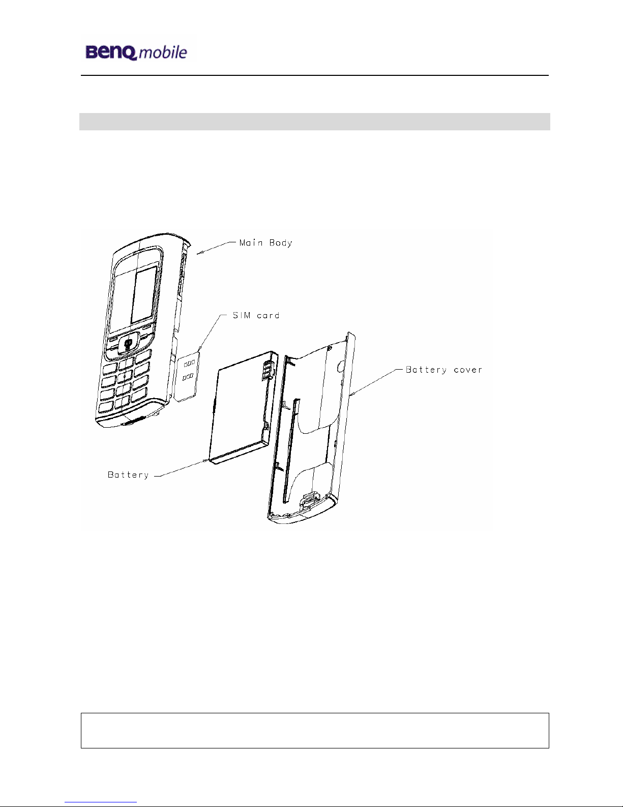
3Unit Description of A31.............................................................................................................5
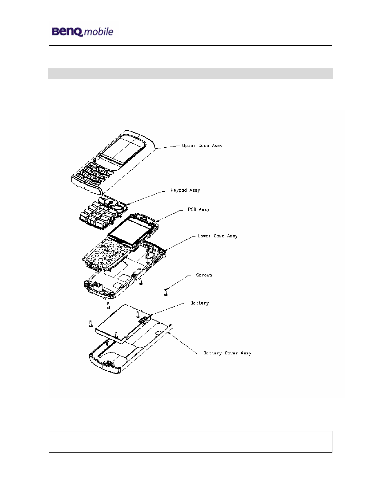
4Exploded View of A31...............................................................................................................6
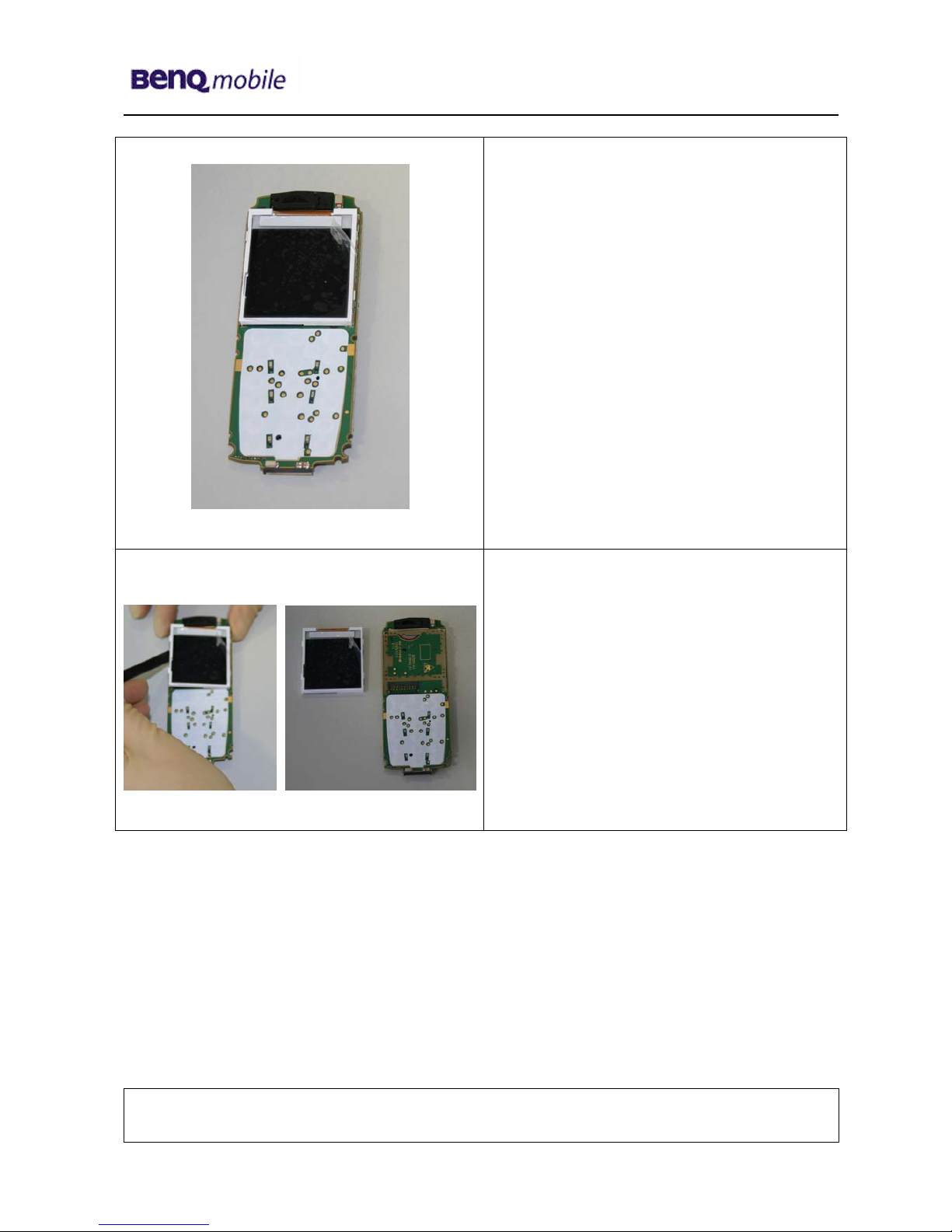
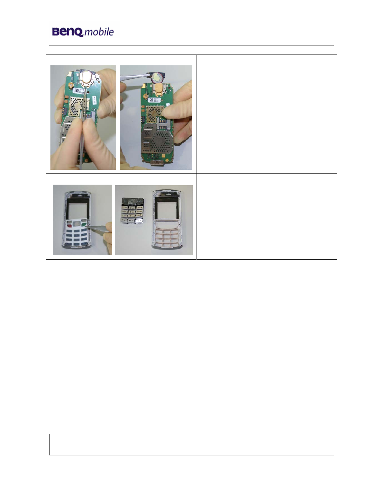
5Disassembly of A31 ..................................................................................................................7
6Assembly of A31 .....................................................................................................................11
7BenQ Mobile Service Equipment User Manual.....................................................................15
8GRT Software: Functionality Configuration..........................................................................16
9GRT Software: Regular Usage ...............................................................................................18
10 JPICS (Java based Product Information Controlling System)............................................23
11 International Mobile Equipment Identity, IMEI......................................................................29
12 General Testing Information...................................................................................................30
13 Introduction of Service Repair Documentation for Level 3 Basic Repairs – A31..............36
14 List of available Level 3 Basic Parts......................................................................................37
15 Hardware Requirements.........................................................................................................37
16 A31 Board Layout....................................................................................................................38
17 SIM Card Problems .................................................................................................................39
18 IO Connector Problems ..........................................................................................................40
19 Main Keypad Illumination Problems......................................................................................41
20 Connector Battery...................................................................................................................42
21 Display Problems ....................................................................................................................43
22 Connector RF Internal Antenna .............................................................................................44
23 Filter EMI Problems.................................................................................................................46
Company Confidential
2005©BenQ

Release 1.0
Technical Documentation 10/2005
TD_Repair_L2.5L_A31_R1.0.pdf Page 3 of 46
1 Key Feature
Supported Systems Band GSM 900/1800
Band GSM 850/1900
EGSM (GSM phase 2/phase 2+)
GPRS multislot class 8, coding scheme 1-4*
Vocoders FR, HR, EFR, AMR
Stand-by Time Up to 270 h (standard battery)
Talk Time Up to 300 min (standard battery)
Battery Technology
Battery Capacity Li-Ion 820 mAh
Less than 2 h for 100%
Weight 85 g
Volume 75 cm³
Length 102 mm
Width 46 mm
Thickness 17.6 mm
SIM Functionality /
Security Controls
SIM Application Toolkit (Rel. 99)
SIM lock, various levels
PIN 1 & 2 control
Ciphering A5.1 and A5.2
SIM plug-in (3/1.8 V), SAT rel 99
Antenna Integrated
Data Services Mobile Internet access (WAP 1.2.1 & parts of 2.0)
Data download OTA via SMS or WAP
MMS class 3
EMS rel. 4.3
Data services (CSD) at 9.6 Kbps & GPRS
(up to 53.6 Kbps)
Display / Display Illumination 128 x 128 pixels, 65,536 colors, CSTN,
7 lines plus headline
Camera n / a
Connectivity Serial cable
Features 4-way navigation key & two soft keys
65,536 color display
Messaging: SMS, EMS, MMS
32-chord polyphonic ring tones
Basic organizer: event reminder, address book, and calendar
Mobile Phone Manager software, WAP, GPRS
Java MIDP 1.0, Java based games and applications
Speed dialing keys, Programmable soft keys
Handsfree talking
Alarm function
Calculator
Stopwatch
Silent alert (Vibra)
External Antenna Connector in the phone offers an interface for
a built-in car kit
Company Confidential
2005©BenQ

Release 1.0
Technical Documentation 10/2005
TD_Repair_L2.5L_A31_R1.0.pdf Page 4 of 46
2 A31 Interface to Accessories
The car cradle is the same design of the G85 existing design. Nano I/O connector is for G85
generation. The compatible interface is suitable to use the travel charger.
Company Confidential
2005©BenQ

Release 1.0
Technical Documentation 10/2005
TD_Repair_L2.5L_A31_R1.0.pdf Page 5 of 46
3 Unit Description of A31
The A31 Finch is designed as a Mono Block with non-exchangeable housing. The Upper case and
battery cover are painted parts (1k; 2 colours). IMD Lens will be mounted by double adhesive,
display, 128X128(reuse from Pegasus); semi-bridge keypad, 4-way Navi-Key, 12 keys block; IMD
lens (1pcs only); No ID concept will be realized on Battery Cover.
Company Confidential
2005©BenQ

Release 1.0
Technical Documentation 10/2005
TD_Repair_L2.5L_A31_R1.0.pdf Page 6 of 46
4 Exploded View of A31
Company Confidential
2005©BenQ

Release 1.0
Technical Documentation 10/2005
TD_Repair_L2.5L_A31_R1.0.pdf Page 7 of 46
5 Disassembly of A31
All repairs as well as disassembling and assembling have to be carried out in an ESD
protected environment and with ESD protected equipment/tools. For all activities the
international ESD regulations have to be considered.
For more details please check information in c – market
https://market.benqmobile.com/SO/welcome.lookup.asp
There you can find the document “ESD Guideline”.
Step 1
Remove Battery Cover Assy and Battery.
Step 2
Remove screws with the Torque –
Screwdriver T5+
Company Confidential
2005©BenQ

Release 1.0
Technical Documentation 10/2005
TD_Repair_L2.5L_A31_R1.0.pdf Page 8 of 46
Step 3
Remove Vibramotor by using Tweezers.
Step 4
Remove Loudspeaker by using Tweezers.
Step 5
Remove MMI from Upper Case Assy by
using the Alternative Opening Tool
carefully.
Company Confidential
2005©BenQ

Release 1.0
Technical Documentation 10/2005
TD_Repair_L2.5L_A31_R1.0.pdf Page 9 of 46
Step 6
To avoid scratches it is mandatory to place
a protection foil onto the Display!!!
Step 7
Remove Display by using the alternative
opening tool carefully.
Company Confidential
2005©BenQ

Release 1.0
Technical Documentation 10/2005
TD_Repair_L2.5L_A31_R1.0.pdf Page 10 of 46
Step 8
Remove Earphone.
Press the hocks together and lift the
earphone up.
Step 9
Remove keypad by using tweezers.
Company Confidential
2005©BenQ

Release 1.0
Technical Documentation 10/2005
TD_Repair_L2.5L_A31_R1.0.pdf Page 11 of 46
Overview Upper Parts
Overview Lower Parts
Loud-
speaker
Display Screws
Ke
yp
ad
Upper Base
Ass
y
Battery
Cover Assy
PCB Battery
Vibramoto
r
Lower Case
Assy
Earphone
6 Assembly of A31
Step 1
Assemble Keypad by using Tweezers.
Step 2
Assemble Earphone by using Tweezers.
Company Confidential
2005©BenQ

Release 1.0
Technical Documentation 10/2005
TD_Repair_L2.5L_A31_R1.0.pdf Page 12 of 46
Step 3
Assemble Display module.
Step 4
Remove the display protection foil.
Step 5
Assemble Receiver by using tweezers.
Company Confidential
2005©BenQ

Release 1.0
Technical Documentation 10/2005
TD_Repair_L2.5L_A31_R1.0.pdf Page 13 of 46
Step 9
Assemble the Vibramotor by using
tweezers.
Step 10
Assemble MMI and Upper Case Assy.
Step 11
Assemble Lower Case Assy.
Company Confidential
2005©BenQ

Release 1.0
Technical Documentation 10/2005
TD_Repair_L2.5L_A31_R1.0.pdf Page 14 of 46
Step 9
Assemble Battery and Battery Cover Assy.
Company Confidential
2005©BenQ

Release 1.0
Technical Documentation 10/2005
TD_Repair_L2.5L_A31_R1.0.pdf Page 15 of 46
7 BenQ Mobile Service Equipment User Manual
Introduction
Every LSO repairing BenQ Mobile handset must ensure that the quality standards are
observed. BenQ Mobile has developed an automatic testing system that will perform all
necessary measurements. This testing system is known as:
BenQ Mobile Service Equipment
•For disassembling / assembling
Torque – Screwdriver
Part Number: F 30032 – P 228 – A1
Opening tool
(Case opening without destroying)
Part Number: F 30032 – P 38 – A1
Alternative Opening tool
Part Number: F30032 – P583 – A1
Tweezers
•For testing
All mobile phones have to be tested with the GRT – Software. The service partner is
responsible to ensure that all required hardware is available.
For additional Software and Hardware options as well as the supported GRT equipment,
please check the GRT User manual.
Company Confidential
2005©BenQ

Release 1.0
Technical Documentation 10/2005
TD_Repair_L2.5L_A31_R1.0.pdf Page 16 of 46
8 GRT Software: Functionality Configuration
Sep 1: Select „Settings >> SWUP / JPICS”
Step 2: Proceed as follows:
¾Select all required Variants you need to repair (click onto the “+” in
front of the product name.
¾Check Com-Port setting. If necessary change it
¾Check speed setting. Select always the lowest speed if your PC
does not have a fast serial card
¾Enter the value for “JPICS Server Timeout”. Be careful, this value
defines how long GRT tries to reach the server until you get an
error message. Do not select a very long time
2
4
1
3
Company Confidential
2005©BenQ

Release 1.0
Technical Documentation 10/2005
TD_Repair_L2.5L_A31_R1.0.pdf Page 17 of 46
Step 3: Connect to GRM Server
•Choose in the section „GRM” the „Connect to GRM Database“ functionality
1
2
3
It you IT infrastructure parameter
have changed, use this button to
move to the configuration mask
Activate always both boxes if you
connect to the database. Start
with “Connect”
Enter your GRT-Username and
Password into this fields
•End the connection with a click onto the „Exit button“ (appearing after successful data
exchange)
GRT Software has now finished all required settings and configuration tasks. All
files have been down- and uploaded.
In dependency of the selected number of mobile phones and variants the volume
of transferred date could be (~100MB)
Company Confidential
2005©BenQ

Release 1.0
Technical Documentation 10/2005
TD_Repair_L2.5L_A31_R1.0.pdf Page 18 of 46
9 GRT Software: Regular Usage
Step 1: Select the section SWUpdate
Step 2: Choose the area you want to work with
•Personal Repair
Personal Repair is always accessible. Basis for the decision if a SW-Update is
authorised by BenQ Mobile is the so called Service Release-Table .
Example: Mobile Phone has already SW50. Service -Release-Table shows SW50
In this case SW-Update is not necessary and therefore not authorised
In any case customer data can be erased on request. (xfs and mapping have to be
activated) Of course JPICS hardware and authorisation have to be available.
•Operator SWAP
This area is only accessible if you are released by the service management to
perform SW-Updates for Net-Operators. Basis for the decision if a SW-Update is
authorised by BenQ Mobile is the so called Master-Table .
Customer data will be erased without any exception and any chance to influence by
the user. JPICS hardware and authorisation have to be available.
•Operator SWUpdate
This area is only accessible if you are released by the service management to
perform SW-Updates for Net-Operators. Basis for the decision if a SW-Update is
authorised by BenQ Mobile is the so called Master-Table .
Like in “Personal Repair” customer data can be erased on request. (xfs and mapping
have to be activated) Of course JPICS hardware and authorisation have to be
available.
Company Confidential
2005©BenQ

Release 1.0
Technical Documentation 10/2005
TD_Repair_L2.5L_A31_R1.0.pdf Page 19 of 46
9.1 Window explanation
This general explanation is valid for all SW-Update channels
(Personal Repair, Operator SWAP, Operator SWUpdate)
Stop / leave SW-Update
Start button for SW-
Update
Shows the different SW –Versions
a) SW inside the mobile phone
b) Version of Service Release Table
SW
c
)
Version of Master Table SW
Window to select the mobile
phone CPU
After using „Check Variant“ Phone IMEI-
Number will be shown here
Select boxes for:
Content = xfs
Settings = mapping
Attention:
A
ctivation of the boxes
will cause erase of
customer date while SW-
Update
1.1.1.1.1.1.1 Automatic read
out function of phone
type/Variant. Appearing in the
window above.
Remarks:
In case of malfunction please check
oIs the correct phone type selected
oIs the correct COM-Port selected
oIf a variant is missing, move back to Settings select the missing variant and
conncet the GRM Server. Then continue with SW-Update.
Company Confidential
2005©BenQ

Release 1.0
Technical Documentation 10/2005
TD_Repair_L2.5L_A31_R1.0.pdf Page 20 of 46
5.1 9.2 Case 1: Personal Repair (green)
Step 1: Carry out step 1 – 4 to start SW-Update.
1.1.1.1.1.1.2 Read out phone
type/Variant. >>Appears in the
window above.
3
Choose if customer data shall be erased.
If “Yes” activate the boxes in front of xfs
and mapping
Start SW-Update
Select the mobile phone CPU type
4
1
2
Remarks:
-The decision about a BenQ Mobile authorised SW-Update depends only on
the Service Release-Table .
-The SW which is booted by GRT can be below the SW mentioned in the
Service Release Table, if this SW is not released for the Net-Operator
-If xfs and mapping are activated, GRT will erase in any case the customer
data even if the action is cancelled.
-If the user wants to download an other variant then the automatically identified
one, he has simply to select an other variant from the list. Afterwards he has to
start the SW-Update
Company Confidential
2005©BenQ
Table of contents
Other BenQ Cell Phone manuals