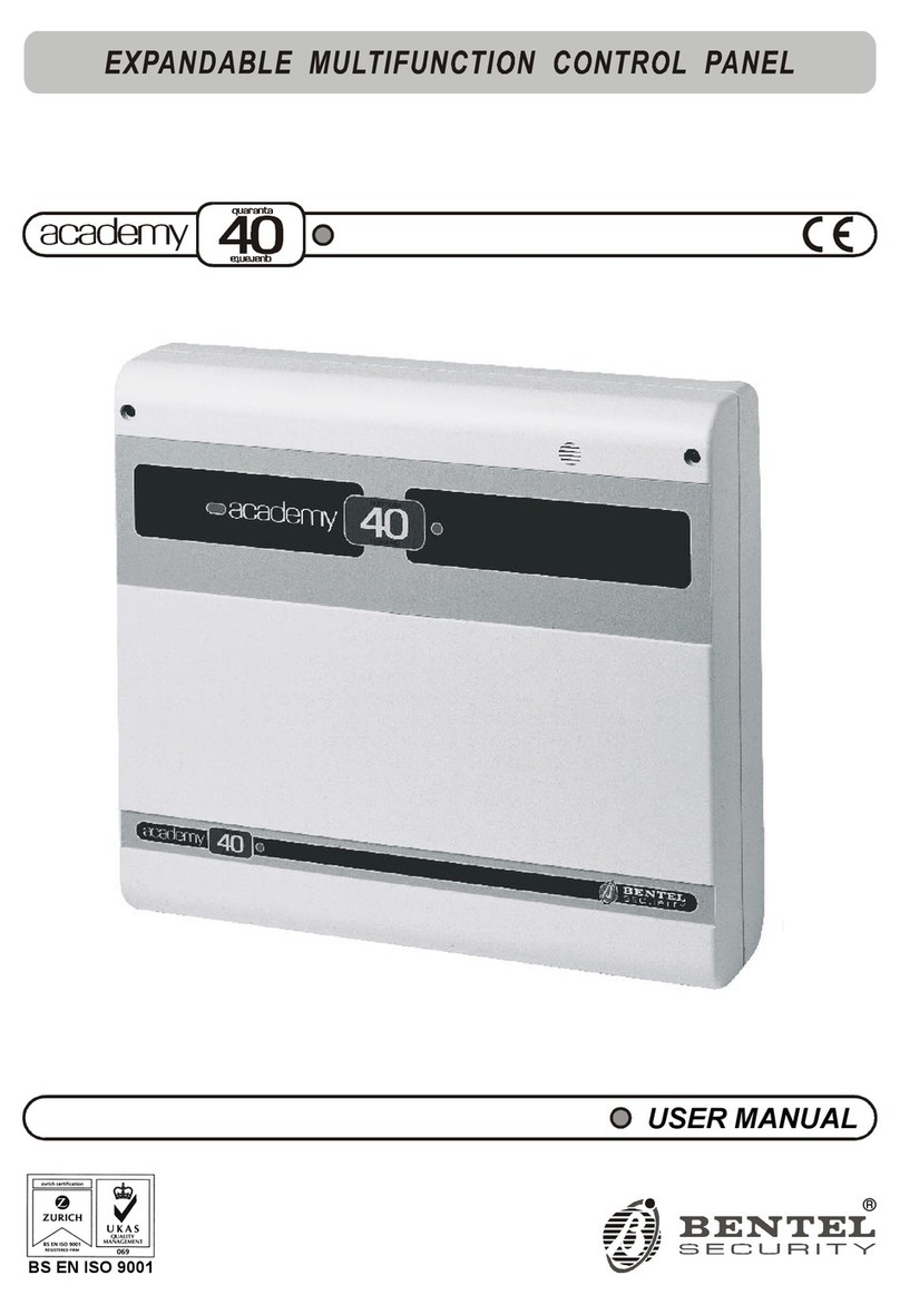
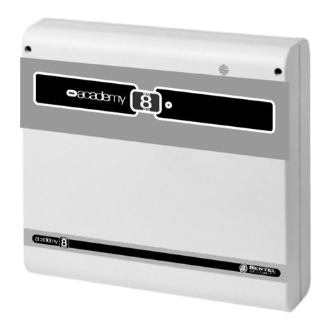
Bentel academy 40 User manual

®
INSTALLATION MANUAL
BS EN ISO 9001

This Control panel has been developed and manufactured according to the highest standards of qual-
ity, reliability and performance adopted by BENTEL SECURITY srl.
Installation of this Control panel must be duly carried out in accordance with the local laws in
force.
BENTEL SECURITY srl shall not be responsible for damage arising from improper installation or main-
tenance by unauthorized personnel.
Use the Omnia--Academy40 3.0 software release or a successive release to program this Control panel.
Where features and programming procedures apply to Academy40 and Academy40/S the product will be
referred to as the Panel.
Where features and programming procedures apply to one of the appliances in particular the product
name will be specified.
Academy40 and Academy40/S comply with:
Low voltage: EN 60950/1996 + A4/1997
Emission: EN 50081-1/1992
Immunity: EN 50130-4/1995 + A1/1999
Burglar control: CEI 79/2aEd. 1993
Terminal Equipment (TE): TBR 21 -- 1/1998
BENTEL SECURITY srl reserves the right to change the technical specifications of this product with-
out prior notice.

CONTENTS
INTRODUCTION 5
Overview . . . . . . . . . . . . . . . . . . . . . . . . . . . 5
Main features . . . . . . . . . . . . . . . . . . . . . . . . . 6
Academy40 Panel . . . . . . . . . . . . . . . . . . . . . . 7
Accessories . . . . . . . . . . . . . . . . . . . . . . . . . . 8
Specification . . . . . . . . . . . . . . . . . . . . . . . . . 10
PARTS 11
Main unit . . . . . . . . . . . . . . . . . . . . . . . . . . . . 11
Keypad . . . . . . . . . . . . . . . . . . . . . . . . . . . . 13
Key reader and Digital key . . . . . . . . . . . . . . . . . . 15
Input and Output expanders . . . . . . . . . . . . . . . . . . 16
INSTALLATION 17
Installation steps . . . . . . . . . . . . . . . . . . . . . . . 17
Maximum Configuration . . . . . . . . . . . . . . . . . . . 20
Terminal board description . . . . . . . . . . . . . . . . . 21
Panel . . . . . . . . . . . . . . . . . . . . . . . . . . . . . . 21
BPI devices . . . . . . . . . . . . . . . . . . . . . . . . . . 22
Schematic diagrams . . . . . . . . . . . . . . . . . . . . . 22
BPI device connection . . . . . . . . . . . . . . . . . . . . 23
BPI bus wiring . . . . . . . . . . . . . . . . . . . . . . . . . 24
Alarm sensor connection . . . . . . . . . . . . . . . . . . 24
Fire sensors . . . . . . . . . . . . . . . . . . . . . . . . . . 25
Alarm signalling devices . . . . . . . . . . . . . . . . . . 26
Tamper terminals . . . . . . . . . . . . . . . . . . . . . . . 27
Telephone-line connection . . . . . . . . . . . . . . . . . 27
Power supply connection . . . . . . . . . . . . . . . . . . 28
PROGRAMMING 29
Customer data . . . . . . . . . . . . . . . . . . . . . . . . 30
Configuration . . . . . . . . . . . . . . . . . . . . . . . . . 31
Keypads . . . . . . . . . . . . . . . . . . . . . . . . . . . . 31
Key readers . . . . . . . . . . . . . . . . . . . . . . . . . . 32
Zones . . . . . . . . . . . . . . . . . . . . . . . . . . . . . 32
Zone Table Description . . . . . . . . . . . . . . . . . . . . 32
Zone programming . . . . . . . . . . . . . . . . . . . . . . 33
Type . . . . . . . . . . . . . . . . . . . . . . . . . . . . . . 33
Attributes . . . . . . . . . . . . . . . . . . . . . . . . . . . . 34
Balance Type . . . . . . . . . . . . . . . . . . . . . . . . . 34
Cycles . . . . . . . . . . . . . . . . . . . . . . . . . . . . . 35
Partition . . . . . . . . . . . . . . . . . . . . . . . . . . . . 35
Sensitivity . . . . . . . . . . . . . . . . . . . . . . . . . . . 35
Voice messages . . . . . . . . . . . . . . . . . . . . . . . 35
Outputs . . . . . . . . . . . . . . . . . . . . . . . . . . . . 36
Outputs page . . . . . . . . . . . . . . . . . . . . . . . . . 36
Description . . . . . . . . . . . . . . . . . . . . . . . . . . . 36
Reserved . . . . . . . . . . . . . . . . . . . . . . . . . . . 37
Type . . . . . . . . . . . . . . . . . . . . . . . . . . . . . . 37
Attribute . . . . . . . . . . . . . . . . . . . . . . . . . . . . 37
Times . . . . . . . . . . . . . . . . . . . . . . . . . . . . . 37
Off Time . . . . . . . . . . . . . . . . . . . . . . . . . . . . 37
Partitions . . . . . . . . . . . . . . . . . . . . . . . . . . . 38
Telephone . . . . . . . . . . . . . . . . . . . . . . . . . . 39
Answer . . . . . . . . . . . . . . . . . . . . . . . . . . . . 39
Dialling mode . . . . . . . . . . . . . . . . . . . . . . . . . 40
PSTN line parameters . . . . . . . . . . . . . . . . . . . . 40
Answering machine . . . . . . . . . . . . . . . . . . . . . . 40
Dialler . . . . . . . . . . . . . . . . . . . . . . . . . . . . . 41
Dialler Telephone Numbers . . . . . . . . . . . . . . . . . 41
Messages . . . . . . . . . . . . . . . . . . . . . . . . . . . 42
Actions . . . . . . . . . . . . . . . . . . . . . . . . . . . . 42
Digital Communicator . . . . . . . . . . . . . . . . . . . . 43
Digital Communicator telephone numbers . . . . . . . . . . 43
Actions . . . . . . . . . . . . . . . . . . . . . . . . . . . . 44
Teleservice . . . . . . . . . . . . . . . . . . . . . . . . . . 46
Event-Actions . . . . . . . . . . . . . . . . . . . . . . . . 47
Events Table . . . . . . . . . . . . . . . . . . . . . . . . . 47
Priority telephone actions . . . . . . . . . . . . . . . . . . . 47
Actions . . . . . . . . . . . . . . . . . . . . . . . . . . . . 48
View event details . . . . . . . . . . . . . . . . . . . . . . . 48
Clear actions . . . . . . . . . . . . . . . . . . . . . . . . . 48
Events description . . . . . . . . . . . . . . . . . . . . . 48
Alarm events . . . . . . . . . . . . . . . . . . . . . . . . . 48
Generic Events . . . . . . . . . . . . . . . . . . . . . . . . 50
Spot events . . . . . . . . . . . . . . . . . . . . . . . . . . 52
Test event . . . . . . . . . . . . . . . . . . . . . . . . . . 53
Keypad Codes . . . . . . . . . . . . . . . . . . . . . . . . 53
User Code Description . . . . . . . . . . . . . . . . . . . . 53
Code attributes programmed by the Installer . . . . . . . . . 54
User Parameters . . . . . . . . . . . . . . . . . . . . . . . 54
How to program Access Codes . . . . . . . . . . . . . . . . 56
Attributes programmed by the user . . . . . . . . . . . . . . 57
Digital keys . . . . . . . . . . . . . . . . . . . . . . . . . . 58
Super keys . . . . . . . . . . . . . . . . . . . . . . . . . . 58
Filter times . . . . . . . . . . . . . . . . . . . . . . . . . . 58
Options . . . . . . . . . . . . . . . . . . . . . . . . . . . . 59
LCD strings . . . . . . . . . . . . . . . . . . . . . . . . . 59
Clock . . . . . . . . . . . . . . . . . . . . . . . . . . . . . 59
Installer code . . . . . . . . . . . . . . . . . . . . . . . . 60
On-site Downloading from computer . . . . . . . . . . . 61
Remote Downloading from computer . . . . . . . . . . . 61
Programming from Keypad . . . . . . . . . . . . . . . . . 62
Reset default . . . . . . . . . . . . . . . . . . . . . . . . . 62
Defaults . . . . . . . . . . . . . . . . . . . . . . . . . . . . 63
A basic system . . . . . . . . . . . . . . . . . . . . . . . 64
Connections . . . . . . . . . . . . . . . . . . . . . . . . . . 64
Programming . . . . . . . . . . . . . . . . . . . . . . . . . 64
System use . . . . . . . . . . . . . . . . . . . . . . . . . . 64
3

OmniaVOX 65
Features . . . . . . . . . . . . . . . . . . . . . . . . . . . . 65
Parts identification . . . . . . . . . . . . . . . . . . . . . . 65
Installation . . . . . . . . . . . . . . . . . . . . . . . . . . 65
Expand Listen-in partitions . . . . . . . . . . . . . . . . . 66
Manual selection . . . . . . . . . . . . . . . . . . . . . . . . 67
Auto-select mode . . . . . . . . . . . . . . . . . . . . . . . 68
Manual and Auto-select mode . . . . . . . . . . . . . . . . . 68
APPLICATIONS 69
Fast arming . . . . . . . . . . . . . . . . . . . . . . . . . . 69
Temporary disarming (patrol) . . . . . . . . . . . . . . . 70
Common partition management . . . . . . . . . . . . . . 71
Several outputs assigned to the same event . . . . . . . 72
Multi-output event . . . . . . . . . . . . . . . . . . . . . . 73
Recognition of multiple codes . . . . . . . . . . . . . . . 74
Disarming under duress . . . . . . . . . . . . . . . . . . 75
Solution no. 1 . . . . . . . . . . . . . . . . . . . . . . . . . 75
Solution no. 2 . . . . . . . . . . . . . . . . . . . . . . . . . 75
Dialler . . . . . . . . . . . . . . . . . . . . . . . . . . . . . 76
Stop Alarm by Digital key . . . . . . . . . . . . . . . . . . 79
4Expandable Multifunction Control Panel Academy40

INTRODUCTION
Overview The philosophy of the Academy40 Control Panel is flexibility. It can be adapted to all types of installations, and can
be expanded, programmed and operated with great ease.
Academy40 and Academy40/S have 8 input zones----expandable to 40, and 4 outputs----expandable to 36.
Partitions The 8 partitions can be armed / disarmed individually or as groups----by means of digital keys, codes or Panel in-
puts. A partition can be programmed as dependent on other partitions----for automatic "Common partition" con-
trol.
Events and
actions Interaction between the Inputs, Outputs and Telephone-dialler (voice or digital) can be programmed as per re-
quirements.
The three basic actions----output, digital dialler and voice dialler actions can be assigned to the Academy40 events
(445 events).
Telephone
functions Academy40 can manage up to 32 telephone numbers. Four telephone numbers can be assigned to the digital
communicator----each with a different customer code and communication protocol.
Four telephone numbers can be assigned to Teleservice thus allowing the Panel to communicate with the installer
modem.
OmniaVOX 14 different Voice messages (to be recorded by the Installer) can be sent to the 16 telephone numbers managed
by the OmniaVOX board telephone-dialler function.
The OmniaVOX board also provides an answering-machine function (one of the 14 Voice messages can be as-
signed to this function).
Voice communication with the Panel (after receiving a dialler call, or when the Panel is answering an incoming
call) allows:
----Listen-in
----Two-way communication (talk-listen)
----Input status inquiry with voice answer from the Panel
----remote ON / OFF control of Panel devices
----Partition arming / disarming, alarm reset, stop calls etc.
Programming The BENTEL Security Suite allows Panel programming, Customer database management and real-time monitor-
ing of the Panel----by connecting to the RS232 interface, or to teleservice.
+The Panel can also be programmed from the keypads.
INTRODUCTION 5

Main features Burglar Panel
rUp to 40 alarm zones----8 on Main unit----24 on 6 Input expanders (4 zones per expander)----8 on 8 keypads (1
zone per keypad)
rUp to 40 alarm zones----2 relays and 2 open collectors on Main unit----32 outputs on 8 Output expanders (4 outputs
per expander)
rUp to 8 keypads with back lighted LCD
rUp to 16 Electronic-key readers
r1 or 2 Power stations (3 A or 5 A) monitored by the Panel
r4 wire bus (protected against short circuit) for connection of remote devices
rProgrammable balance type, function mode and alarm type----for all zones
rInput zones can be programmed to send specific commands to the Panel
rAll outputs are programmable as bistable or cyclic with programmable cycle and standby times
r8 programmable partitions----each with own zones, keypads, key readers, outputs and times
r31 user codes with programmable priority and function control
rUp to 250 programmable digital keys
rA 16 character label (identifier) can be assigned to each partition, zone, keypad, key reader, code, digital key,
etc.----the assigned label will be shown on the keypad screen during user operations
rSaves 200 events with date, time and user
rRS232 interface for Panel programming and monitoring
rSoftware (runs under Windows) for Panel programming, teleservice and telemonitoring
Telephone functions
rDTMF and Pulse dialling
r32 telephone numbers available for telemonitoring, teleservice and voice calls
rBuilt-in Digital multiprotocol communicator for DTMF and pulse protocol management
r10 different immediate alarm calls from keypad
rProgrammable test call
rDouble call
rLine sharing with answering device
r1200 baud FSK integrated modem for teleservice management
Telephone functions with OmniaVOX optional board
rTelephone dialler for Voice message control----14 different Voice messages that can be sent to 16 telephone num-
bers
rRemote Inquiry to the Panel with voice answer
rRemote output-control, partition arming and alarm reset from Panel
rRemote listen-in and multipoint telephone-communication (talk-listen)
rAnswering-machine function
6Expandable Multifunction Control Panel Academy40

Academy40 Panel
Basic Panel The basic system comprises a Main unit and a keypad. Academy40 is available in the following models:
ØAcademy40 ---- 8 zone Main unit expandable to 40 with 1.5 A linear battery and keypad.
Academy40/S ---- 8 zone Main unit expandable to 40 with 3 A switching battery and keypad.
Expanders Academy40 and Academy40/S can support:
----up to 6 input expanders----each with 4 zones;
----up to 8 output expanders----each with 4 open-collector outputs.
Control devices Up to 16 key readers, and 8-LCD keypads can be connected to the Panel.
The key readers are available in the following models:
----Wall mounting (BP13W)
----Flush mounting (BP13)
----Flush mounting (ECLIPSE3----no electrical contacts).
The operating principles of all three models are the same, however, the BP13W and BP13 key readers operate
through electrical contacts, and have a control button on the digital key (DKC).
The ECLIPSE3 has no electrical contacts, and the control button is inside the key reader slot and not on the key
(SAT)----thus making the ECLIPSE3/SAT model more resistant to oxidising agents and wear.
OmniaVOX Optional board for voice call management and remote control.
BENTEL Security
Suite The BENTEL Security Suite (runs under Windowsenvironment) allows Panel programming, Customer data-
base management, and Real-time monitoring.
OmniaMOD
modem The OmniaMOD modem----and relevant software can manage manual and automatic teleservice calls thus allow-
ing the installer to keep the computer buffer updated.
The OmniaMOD V2 modem can receive calls for real-time information on monitored systems.
Remote power
station The optional 5 A power-station (to be connected to the bus) will power the remote devices in the event of blackout.
The Panel can monitor all the power station events (battery trouble, mains failure, etc.). Two power stations can be
connected to the bus.
INTRODUCTION 7

nAccessories
Academy40 8 zone Main unit expandable to 40 with 1.5 A linear battery and keypad
Academy40/S 8 zone Main unit expandable to 40 with 3 A switching battery and keypad
OMNIA/TAST-R Keypad with back lighted LCD
OMNIA/4IN 4-input expander module
OMNIA/4OUT 4-output expander module
---- Expander module holder 108 x101 mm
DEVMSSG Tamper Switch
OMNIA/VOX Voice board
OMNIA/VOX-MS Microphone and loudspeaker for ambient listen-in
ECLIPSE3MA Flush mounting key reader----TICINO magic
ECLIPSE3IN Flush mounting key reader----TICINO international
ECLIPSE3GE Flush mounting key reader----GEWISS
ECLIPSEGP Flush mounting key reader----GEWISS playbus
SAT Digital key
BPI3 Flush mounting key reader TICINO magic
BPI3LIV Flush mounting key reader TICINO living
BPI3INT Flush mounting key reader TICINO international
BPI3LGT Flush mounting key reader TICINO light
BPI3GEW Flush mounting key reader GEWISS
BPI3GP Flush mounting key reader GEWISS playbus
BPI3-GN Flush mounting key reader GEWISS noir
BPI3DEL Flush mounting key reader DELTA
BPI3-DN Flush mounting key reader DELTA noir
BPI3VI Flush mounting key reader VIMAR idea
BPI3VIB Flush mounting key reader VIMAR bianco
BPI3-AVE Flush mounting key reader AVE
BPI3-AN Flush mounting key reader AVE noir
BPI3W Wall mounted key reader
DKC Digital key
OMNIA/4R 4-relay module for the output expanders
OMNIA/MOD-V1 Teleservice modem
OMNIA/MOD-V2 Teleservice and remote monitoring modem
CVSER/9F9F Serial cable for computer connection
ADSER/9M25F 25-pin adapter for serial ports
SECURITY SUITE Bentel Security Suite
BXM12/30 3 A remote power-station
BXM12/50 5 A remote power-station
8Expandable Multifunction Control Panel Academy40

RL1
RL2
RL3
RL4
+12
OC1
OC2
OC3
OC4
AS
1 2 3 4
Omnia4IN
INPUTEXPANDER
Omnia4OUT
OUTPUTEXPANDER
Omnia4R
RELAY MODULE
4prog.inputzones
Upto6devices Upto8devices Upto5A
1prog.output(1Arelay)
3prog.outputs(0,1Ao.c.)
1Aor3Apowersupply
Telephonecommunicator
V2:remotemonitoring
Vocalmonitorofinputs
Managementofremoteloads
Two-way conversation
Remotelistening
14 recordablemessages
Telephonedialler
Answering machineUpto4boards
Upto2devices
8prog.inputzones
V1:teleservice
OnboardBuzzerComparmentfor17 Ahbattery
4prog.outputs(0,15 Ao.c.)4250 V-8Arelays
BPIBus
Upto16 devices
BPI3
KEYREADER
Upto250
DKC
ELECTRONICKEY
1prog.inputzone
Upto8devices
OmniaTAST-R
LCDKEYPAD
BXM12
POWERSTATION
Academy40
MAINUNIT
OmniaMOD
MODEM
4wirecable
5wirecable
up to50 m
OmniaVOX
VOCALBOARD
OmniaVOX-MS
MIC./SPEAKERBOARD
Sensors
Sensors
Siren
Siren
Telephoneline
Figure 1 Academy40 system

Specification
Model Academy40 Academy40/S
Voltage 230 V 50 Hz ±10%
Max. input 0.2 A 0.5 A
Max. power 45 W 115 W
Insulation class Class II Class I
Power supply
Battery-charger 13.8 V 1.5 A 13.8 V 3 A
Max. current available
for peripherals 1 A 2 A
Battery
(Make and Model)
12 V - 7 Ah
YUASA
NP 7-12 FR
or equivalent with UL94-V2 (or higher) case flame class
Operating temperature
range 5 ÷40 °C
Dimensions
(W x H x D) 309 x 227 x 89 mm
Weight
(without battery) 1.9 Kg 1.4 Kg
Complies with EN
standard
EN 50081-1/1992
EN 50082-1/1992
EN 41003:1997
EN 60950:1992 + A1:1993 + A2:1993 + A3:1995 + A4:1996
79/2 2nd Ed. 1993 - Performance level II
Accessory Absorption Dimensions (WxHxD)
Academy40/S Main Board 100 mA ----
Keypad 50 mA 160 x 73 x 30 mm
Flush mounting Key reader 30 mA ----
Wall mounting Key reader 30 mA 51 x 73 x 28 mm
Input Expander 15 mA 108 x 101 x 34 mm
Output Expander 20 mA
4-relay module 120 mA
Voice board + Microphone / Loudspeaker board 20 mA ----
Power station 20 mA 234 x 345 x 96 mm
10 Expandable Multifunction Control Panel Academy40

PARTS
The following tables hold brief descriptions of the main parts of the system, and the meanings of the ON / OFF
status of the LEDs. The numbers in boldface refer to the parts in the diagrams.
nMain unit
PART DESCRIPTION
1Box screws (2)
2Tamper microswitch (optional for Academy40 and Academy40/S----order code DEVMSSG)
3Holes (4) for back box screws (Ø 5 mm)
4Terminal boards
5Stop alarm jumper: > alarm enabled (default); > alarm disabled
6RS232 serial port
7Jumper (MEM): saves programmed parameters during blackout
> programmed parameters will be lost (default)
> programmed parameters will be saved
8Make / Break jumper
9OmniaVOX board connector
10 Reserved jumper: leave the jumper at 5V
11 Cable passage
12 Battery housing: 12 V - 17 Ah maximum
13 Power supply section (see figure 3)
14 Snatch microswitch bracket
15 Snatch microswitch (optional for Academy40 and Academy40/S----order code *)
16 Protection fuse for terminal [+] BPI bus (F 3.15A 250V)
17 Snatch microswitch connector (15): connect a jumper to the connector terminals when not in use
18 Jumper to disable the Tamper (2) and Snatch (15) microswitches:
> tamper and snatch microswitches are enabled (default)
> tamper and snatch microswitches are disabled
19 Protection fuse for terminal [+B] (F 3.15A 250V)
+
LI
LE L3 L5 L7 –CR
L2L1 L4 L6 L8 +B OC2 OC1 OC ACC1 NC1 NA1
ASB
2 6 19
10 2314 27
1 5 92213 26
3 7 20
11 2415 2817 30
4 8 21
12 2516 2918 31 32
3
2
17
18
6
8
3
9
7
14
16
10
11
1
5
4
12
3
15
1
19
13
3
Figure 2 Main unit parts
PARTS 11

PART DESCRIPTION
20 Mains LED
21 Fine adjustment trimmer----output voltage
22 External device power terminals (13.8 V )
23 Mains voltage connection terminals (230 V / 50 Hz)
24 Battery plugs
25 Plastic pin (to be removed when opening the switching-power supply)
26 Power supply fuse: Academy40 = F 250 mA 250V; Academy40/S = F 2A 250V
27 Battery fuse----protects against polarity inversion (F 8A 250V)
LED MEANING
Mains ON: Mains OK
Battery ON: battery low or empty
BPI Bus ON: communication trouble on BPI bus
F 250mA 250V
F250mA250V
L
L
N
N
230V
50Hz
ƒ
230V
50Hz
ƒ
D5.0 NNL230V 1.0 271099
323130 AC
21 22 23
27 26
25
24
20
26
27
23
24
Figure 3 Switching and linear power supply units
12 Expandable Multifunction Control Panel Academy40

nKeypad
ICON MEANING
Partitions armed
Alarm memory
Trouble
Open Panel
Tamper line alarm
Device tamper
False key on key reader
Peripheral device not found
Teleservice enabled
Answering device enabled
Telephone line engaged
28
29
Figure 4 Control Keypad parts
PARTS 13

PARTS DESCRIPTION
28 Flip
29 LEDs window
30 Box screws (4)
31 LCD
32 Terminal identifier----in accordance with device address
33 Reference pins (2)
34 Connection terminals
35 PCB clips (2)
36 Snatch microswitch
37 Device identifier----in accordance with dipswitch configuration 39
38 Tamper switches
39 Address dipswitches
40 PCB clips (2)
41 Cable passage
42 Holes (2) for back box screws (Ø 4 mm)
43 Snatch microswitch hole
44 Buzzer
45 Buzzer plug
#
34 5 6 7 8
0AB
EXC
ESC
1 2
9
PRG
ON RES
OFF
13572468
21
ON
3 4
#
34 5 6 7 8
0AB
EXC
ESC
1 2
9
PRG
ON RES
OFF
Z9RC
1
44
45
3332 3638
41 42 43 42 4040
33
38
39
3534 3537
30
31
30
3030
Figure 5 Control Keypad parts
14 Expandable Multifunction Control Panel Academy40

nKey reader and Digital key
The optional key reader is available in several models (flush and wall mounting) refer to "Accessories" for the or-
der codes.
+Figure 6 shows the Magic-box model.
PARTS DESCRIPTION
46 Connection terminals
47 Address dipswitches
48 Device identifier----in accordance with dipswitch configuration 47
49 Cable passage
50 Screw holes (2)
51 Snatch bracket screw hole
52 Snatch microswitch
53 Tamper switch
54 Digital key slot
55 Control button (on Digital key)
LED MEANING
RED ON: All partitions enabled on the Key reader are armed
AMBER ON: Type A arming
GREEN ON: Type B arming
11 22 33 44
21
ON
3 4 21
ON
3 4
11
D5.0BNLDATI31.0081098
*
Omnia/S-DATn.U0805
D5.0BNLDATE31.0201099
46
46
47
47
48
48 54
49
46
47
50
51
52
(a)
(d)
(c)
(e)
(b)
53
50
54
55
55
Figure 6 Parts of the Magic (a) and wall-mounted (b) Key reader, and Digital key (c)
PARTS 15

nInput and Output expanders
PART DESCRIPTION
56 BPI Bus connection terminal
57 Device identifier----in accordance with dipswitch configuration 59
58 Input Zone terminal board
59 Address dipswitches
60 Tamper and Snatch bypass jumper:
> switches unbypassed
> switches bypassed (default)
61 Snatch microswitch
62 Tamper switch
63 Buzzer
64
Buzzer mode jumper:
>buzzer bypassed (default)
>buzzer will be activated when terminal [OC4] opens
>buzzer will be activated when terminal [OC4] switches to ground
65 Open-collector output terminal board, 150 mA maximum
66 Terminal identifier----in accordance with the device address
67 Box screws (4)
68 Input or Output expander or 4 relay Module
69 Expander screws (2)
70 Cable passage
71 Screw holes (2) for mounting on model 503 box
72 Opening for cable duct
73 Screw holes (2)
74 Snatch bracket screw hole
75 Tooth (closes tamper switch)
+
C
R
L1
+F
+F
+F
+F
L2
L3
L4
1 2 3 4
1 2 3 4
+
12V
C
OC4
OC3
OC2
OC1
R
1
L17 L18 L19 L20+F +F +F +F
1
O8 O7 O6 O5
1 2 3
56
66
58
57
59
60
62
61
56
63
59
57
64
61
60
62
65
Figure 7 Input and Output Expanders
67
67
68
69
61
70
74
73
69
75
67
67
62
73
72
71
71
Figure 8 Box for Expanders and the 4 Relay module
16 Expandable Multifunction Control Panel Academy40

INSTALLATION
Installation steps The Panel must be located in a safe place.
IMPORTANT The Panel must be at least 2 metres from GSM and radio relay systems.
Step 1 Create a layout----include all alarm detection devices, zone expanders, keypads, key readers, etc.
Step 2 Drill the holes for the cabinet 3 and snatch bracket 14 (see figure 2----"Parts").
Step 3 Pull the connection wires through the hole 11 (see figure 2----"Parts") then attach the cabinet and snatch bracket
to the wall.
+Do not over tighten the snatch bracket screw as this may damage the bracket.
Step 4 Install the additional modules and boards (Omnia4IN, Omnia4OUT, OmniaVOX, etc.----refer to the relevant instruc-
tions).
Step 5 Make all connections----do not connect the Mains until all other wiring is complete.
Mounting the
keypad The keypad should be located in a place where full control of the security system is required.
Step 1 Remove the screws 30 and the keypad box.
Step 2 Unplug the buzzer (plug 45).
Step 3 Remove the PCB----lift the plastic board support clips 35.
Step 4 Drill the holes for the cabinet and snatch bracket screws (42 and 43).
Step 5 Pull the connection wire through the hole 41 then attach the cabinet and snatch bracket to the wall.
Step 6 Replace the PCB and plug the buzzer in (plug 45).
Step 7 Assign the keypad identifier number----use the dipswitches 39----complete the connections on the terminal board
34 then close the keypad box.
41
34
30
30
45
35
42
43
42
35
39
Figure 9 Keypad mounting
INSTALLATION 17

Flush mounting
Key reader Key readers should be located in places where limited control of the security system is required.
Step 1 Assign the key reader identifier number----use the dipswitches 47----complete the connections on the terminal
board 46.
Step 2 Mount the key reader as per figure 10a.
IMPORTANT Ensure that Flush mounting key readers located outdoors are equipped with tamper protection.
ECLIPSE key readers must be at least 2.5 cm apart.
Wall mounting
Key reader The operating principles of wall (BPI3W) and flush mounting key readers are the same, however, the boxes are
different. The Wall mounting key reader is designed for side by side mounting with the keypad.
Step 1 Remove the screws and open the key reader.
Step 2 Drill the holes for the back box and snatch bracket screws (50 and 51).
Step 3 Pull the connection wire through the hole 49 then attach the key reader back box and snatch bracket to the wall.
Step 4 Assign the key reader identifier number----use the dipswitches 47----complete the connections on the terminal
board 46 then close the key reader.
Expanders and
Relay modules The Wall or Flush mounting Input expanders, Output expanders and Relay module must be as near as possible to
the peripherals.
Step 1 Remove the screws 67 and front.
Step 2 Remove the screws 69 and PCB.
Step 3 Remove the knockout (70 or 72 as required).
Step 4 Wall mounting: drill the holes for the box and snatch bracket screws (73 and 74----fig. 13b).
Wall mounting above a model 503 box: drill the hole for the snatch bracket screw only (fig. 13c).
----No drilling is necessary for Flush mounting (fig. 13a).
Step 5 Pull the connection wires through the hole then attach the back box and snatch bracket.
+Position the snatch microswitch as per figure 11----for wall and Flush mounting.
Step 6 Replace the PCB.
Step 7 Assign the expander identifier number----use the dipswitches 59----complete the connections on the terminal
boards.
Step 8 Remove the jumper 60 to enable the tamper and snatch microswitches.
Step 9 Select the Output-expander buzzer mode----use the jumper 64----then close the box.
+The plastic tooth 75 will close the tamper switch.
The Input and Output expanders and the relay module can be mounted inside the Panel (see figure 12) by means
of supports (optional).
IMPORTANT The tamper and snatch microswitches of Input and Output expanders----attached by means of
supports----must be disabled (jumper 60 connected).
to the
tamper line
50
49
50
(b)(a)
51
Figure 10 Flush mounting key reader (a); Wall mounting key reader (b)
18 Expandable Multifunction Control Panel Academy40

69
67
675969 60
70 72
74 73
73
(a)
(b)
(c)
75
67
67
Figure 11 Expander installation: (a) Flush mounting; (b) on view; (c) inside mod.503 box
INSTALLATION 19

Snatch
microswitch Install the Snatch microswitch 15 (optional), as per the instructions below (see fig. 12).
1Use an adequate wire length with a female connector at one end (pitch 2.54 mm), and the other end loose.
2Solder the loose end of the wire to terminals Cand NO of the Snatch microswitch 15.
3Attach the Snatch microswitch to the back box.
+The release lever must be held in place by the plastic pin on the Snatch microswitch bracket (14)
4Remove the jumper from the connector (17) then connect the Snatch microswitch to the connector.
Maximum Configuration
Figure 12 shows the maximum configuration of the Panel.
PART DESCRIPTION
77 Speaker
79 Voltage supply
80 Battery 12 V - 17 Ah max.
81 Voice board
82 Main board
83 Microphone board
NCN O C
83
17
81
82
15
14
79
77
80
Figure 12 Maximum configuration of the Panel
20 Expandable Multifunction Control Panel Academy40
Other manuals for academy 40
1
This manual suits for next models
1
Table of contents
Other Bentel Control Panel manuals
Popular Control Panel manuals by other brands
Mitsubishi
Mitsubishi GOT2000 Series Supplementary Description
DSC
DSC LCD5500Z installation instructions

Texecom
Texecom Veritas Excel Master user guide

schmersal
schmersal SEPK 02.0 operating instructions
Vision
Vision TECHCONNECT CONTROL owner's manual

GE Security
GE Security NX-1750 ProxPad installation manual
