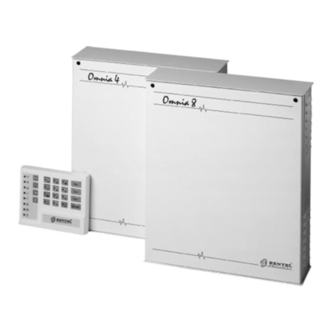
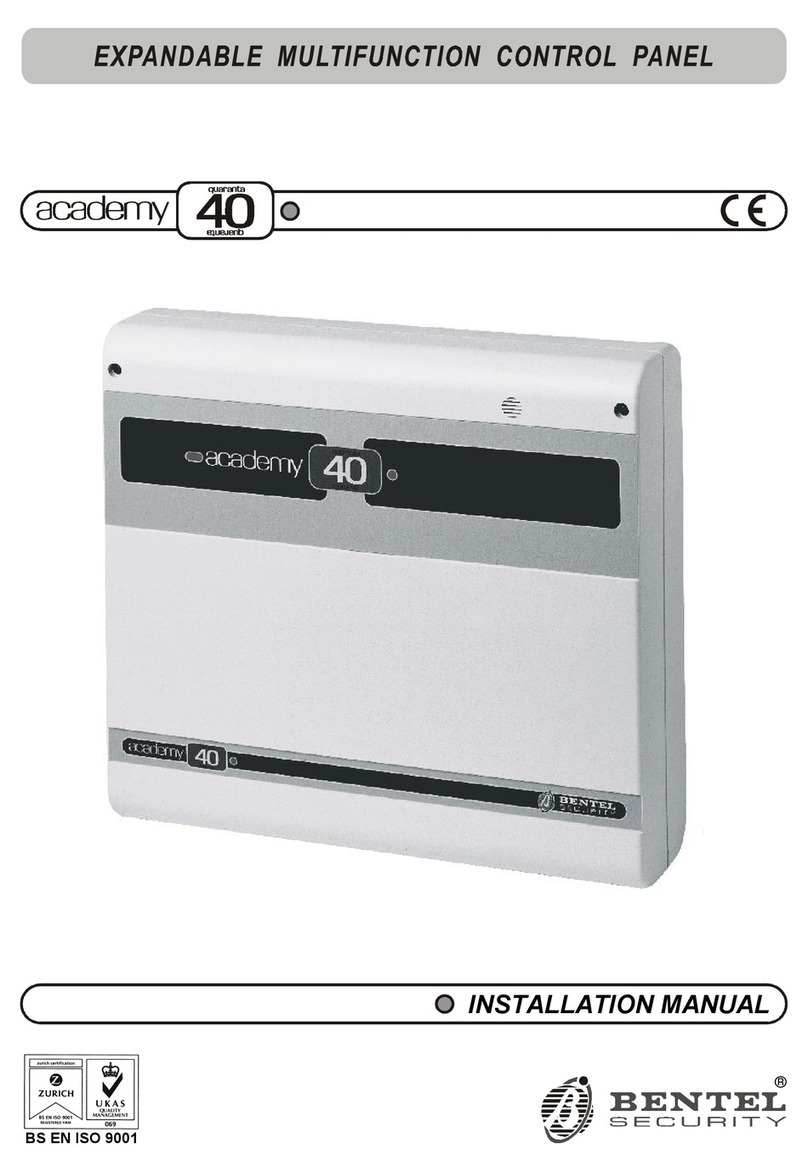
Bentel academy 4 User manual


BENTEL SECURITY srl reserves the right to modify the technical specifications of this product
without prior notice.
Digital Communicator Control Panel
Emission:
Immunity:
Low voltage:
Burglar alarm systems:
EN 50081-1/1992
EN 50130-4/1995+A1/1999
EN 60950/1996 + A4/1997
CEI 79/2 2 Ed. 1993
TBR21-1/1993
a
complies to:
Terminal Equipment(TE):
BENTEL SECURITY declines all responsibility in the event of
unauthorized intervention on the control panel.
The control panel has been developed and made according to the highest
standards of quality, reliability and performance adopted by BENTEL
SECURITY srl.
To make sure your system continues to work as intended, you must test your
system every month. Consult the installer for testing and maintenance
instructions. If your system does not work correctly, call your installer for
service.
Installation of the control panel must carried out strictly according to the
instructions, and in compliance with the safety laws in force.
via Florida - Z.I. Valtesino - 63013 GROTTAMMARE (AP) - ITALY
USER MANUAL: Digital communicator control panel Academy4/8/8L
Istruzioni uso ingles. Bent. Academy4/8/8l ISTUSBLEACADEMY8

CONTENTS
OVERVIEW 5
Glossary . . . . . . . . . . . . . . . . . . . . . . . . . . 5
GENERAL FEATURES 7
The Panel . . . . . . . . . . . . . . . . . . . . . . . . . . 7
The keypad . . . . . . . . . . . . . . . . . . . . . . . . . 8
Digital keys . . . . . . . . . . . . . . . . . . . . . . . . 10
Arming Mode Options . . . . . . . . . . . . . . . . . . 11
DIGITAL KEY CONTROL 13
Global arming . . . . . . . . . . . . . . . . . . . . . . 13
Global disarming . . . . . . . . . . . . . . . . . . . . . 13
Type A arming (Amber) . . . . . . . . . . . . . . . . . 13
Type B arming (green) . . . . . . . . . . . . . . . . . . 14
Stop alarm . . . . . . . . . . . . . . . . . . . . . . . . 14
CONTROL FROM KEYPAD 15
Basic options (from standby status) . . . . . . . . . . 15
Global arming . . . . . . . . . . . . . . . . . . . . . . 16
Global disarming . . . . . . . . . . . . . . . . . . . . 16
Type A or Type B arming . . . . . . . . . . . . . . . . 16
Zone bypass . . . . . . . . . . . . . . . . . . . . . . 16
View armed partitions . . . . . . . . . . . . . . . . . . 17
View bypassed zones . . . . . . . . . . . . . . . . . 17
Menu Options from keypad . . . . . . . . . . . . . . . 18
Reset Alarm Memory . . . . . . . . . . . . . . . . . . 18
Enable / Disable Auto-arming . . . . . . . . . . . . . 19
Enable / Disable Teleservice . . . . . . . . . . . . . . 19
Overtime Request . . . . . . . . . . . . . . . . . . . 20
Teleservice Request . . . . . . . . . . . . . . . . . . 20
Enable / Disable Silent keypad . . . . . . . . . . . . . 20
Enable / Disable Hidden zone status on keypad . . . . 20
Alarm Device Test . . . . . . . . . . . . . . . . . . . 21
Program User Code PIN . . . . . . . . . . . . . . . . . . . . 21 3

Stop alarm . . . . . . . . . . . . . . . . . . . . . . . 22
Stop all Calls . . . . . . . . . . . . . . . . . . . . . . 22
Superkeys . . . . . . . . . . . . . . . . . . . . . . . . 23
Instant alarm call . . . . . . . . . . . . . . . . . . . . 23
View Alarm Memory . . . . . . . . . . . . . . . . . . 23
Trouble Viewing mode . . . . . . . . . . . . . . . . . 24
APPENDIX 25
Zones insert . . . . . . . . . . . . . . . . . . . . . . . 25
Programming sheets . . . . . . . . . . . . . . . . . . 25
Figure 1 Academy4/8, Academy8/L, components
4Security System Control Panel

OVERVIEW
This manual is for Academy 8/L and Academy4/8.Where the specifica-
tions, features and procedures are the same, the system will be referred to
as the Panel. However, where the specifications, features and procedures
differ the system will be referred to by its name.
The Panel has 8 zones and 4 partitions (Academy4 has 4 zones). The ba-
sic system comprises the Panel, built-in Digital Communicator and 1 Key-
pad. The Panel can control up 16 remote devices (key readers / keypads),
with a maximum of 8 keypads (including the one supplied), and 128 differ-
ent digital keys.
Communicator The Digital Communicator can manage 8 telephone numbers for teleserv-
ice and communication with central stations.
Voice messages The optional NCDUEVOX voice board can record up to 8 voice mes-
sages----to be sent to 1 or more of the 8 programmed telephone numbers.
The main features of the Panel are described in this manual. Your Installer
will provide further details for proper use of the system.
Figure 1 shows, keypads, key reader and digital key. Digital keys, although
not indispensable, greatly simplify system control.
Glossary
Arming An option which puts the system IN SERVICE. Violation of the armed parti-
tions will generate an alarm.
Disarming An option which puts the system OUT-OF-SERVICE. Violation of the dis-
armed partitions will not generate an alarm.
Alarm A status which signals violation. Immediate intervention of authorized per-
sons will be required.
Keypad Set of keys used for manual control of the Panel.
Digital Key An electronic control key with a random code (selected from over 4 billion
combinations).
Key Reader A device that reads the digital key.
Alarm Zone A zone where one or more sensors can be connected.
Partition A group of zones that allows system partitioning, each partition can have
its own specific Times, Code PINs and digital keys.
OVERVIEW 5

Exit Time A programmed delay which starts after system arming.
ATTENTION! All persons must leave the protected zone before the
delay ends, otherwise the Panel will generate an alarm.
Entry Time A programmed delay which starts after violation of a delayed zone.
ATTENTION! The system must be disarmed before the delay ends.
Delayed Zone A zone which allows transit.
ATTENTION! An alarm will be generated if the programmed Exit / En-
try time is not respected.
Zone Bypass An option which excludes a zone.
ATTENTION! Violation of a bypassed zone will not generate an
alarm.
Tamper Zone A zone that is active 24 hours per day (24h zone), regardless of the armed
/ disarmed status of the system. An alarm will be generated in the event of
tamper on any of the system components.
Alarm Memory A record of alarm events. The Alarm Memory can be deleted by means of
Automatic or Manual RESET.
Codes 23 Codes are available for the user. The Installer can assign one of the 5
Code Types: - DISABLED - MAIN USER - USER - DURESS - PATROL to
each of the 23 codes. Each code can control specific options and partitions
according to programming. Main User Type codes can assign a 4 to 6 digit
PIN to the other Code Types. When a Code PIN is used on a keypad it can
enable / disable the options on the keypad partitions it controls.
User Pin A modifiable 4 to 6 digit number that accesses the system----to be pro-
grammed by the Main User.
Installer Pin A modifiable 4 to 6 digit number that allows the Installer to access and pro-
gram the Panel parameters.
Teleservice A service provided by the Installer. The Teleservice feature allows the In-
staller to service the Panel via telephone.
Central Station A specialized operations centre that receives and responds to alarm sig-
nalling.
Telemonitoring A service provided by the Central Station. The Telemonitoring function is
for remote control of the system, and communicates coded events to the
Central Station.
6Security System Control Panel

GENERAL FEATURES
The Panel
The Panel cabinet houses the main board, power supply unit, battery, and
the connection terminals of the sensors, sirens and auxiliary devices.
Indicators Academy8/L has five status Indicators (LEDs).
Academy4 and Academy8 have no status indicators.
INDICATOR STATUS
OFF:
ON: Mains failure----Panel powered by battery
Mains supply to Panel OK
OFF:
ON: Battery OK
Low battery or battery trouble
OFF:
ON: Sensor power fuse intact
Sensor power fuse blown
OFF:
ON: Communicator in standby status
Communicator has engaged the telephone line
OFF:
ON: Communication bus OK
Communication bus trouble
GENERAL FEATURES 7

The keypad
The Panel can be programmed and controlled from the keypads.
The following description refers to the NC2TAST keypad. The key func-
tions on the NC2TAST and ICON/KP keypads are identical, however, the
key icons differ.
INDICATORS STATUS (NC2TAST and ICON/KP)
Arm OFF:
ON:
Fast flashing:
All keypad partitions disarmed
At least one keypad partition armed
Viewing armed partitions
Alarm OFF:
Slow flashing:
Fast flashing:
Standby status (no alarm)
Alarm memory
Alarm status
Trouble
OFF:
ON:
Slow flashing:
Panel OK
Trouble: select Trouble Viewing Mode to check
trouble type
Trouble Viewing Mode running
Ready
ON:
OFF:
Fast flashing:
Ready to arm:----arming will not generate an alarm
At least one unbypassed zone is in alarm status:----
arming will generate an alarm
Panel in service status (maintenance)
24h OFF:
Slow flashing:
Fast flashing:
Tamper line balanced
Alarm memorized on the tamper line
Alarm memorized and tamper line open
Open OFF:
ON: Panel closed ( Academy8L only)
Panel open ( Academy8L only)
Bypass
OFF:
ON:
Slow flashing:
Fast flashing:
No bypassed zones
At least one bypassed keypad zone
Panel ready for zone bypass
Viewing bypassed zones
Program.
OFF:
ON:
Slow flashing:
Fast flashing:
Panel in standby status
Panel enabled for Teleservice calls
Panel in programming status
User menu accessed
8Security System Control Panel

NC2/TAST ICON/KP STATUS
KEYS LEDs
Key 1 OFF:
ON: Sensor power fuse intact
sensor power fuse blown
Key 4 OFF:
ON: Panel powered by mains
Mains failure----Panel powered by battery
Key 7 OFF:
ON: Battery OK
Low battery or battery trouble
Key B OFF:
ON: Communication bus OK
Communication bus trouble
Key 0 OFF:
ON: Telephone line OK
Telephone line trouble
Key A OFF:
ON: At least one code not at default
All codes at default
KEYS USER MENU OPTIONS FROM KEYPAD (ICON/KP)
Key 1 Enable / Disable Auto-arming
Key 2 Enable / Disable Teleservice
Key 3 Overtime Request
Key 4 Teleservice Request
Key 5 Enable / Disable Silent keypad
Key 6 Enable / Disable Hidden zone status on keypad
Key 7 Alarm Device Test
Number Keys Standby status----LEDs behind number keys through (correspond-
ing respectively to the zones) will show the zone status:
----OFF = zone in standby status
----Slow flashing = alarm or tamper memorized on the zone
----Fast flashing = zone violation (alarm or tamper)
Buzzer The audible signals emitted by the Keypad buzzer are as follows:
----Key pressed = Short beep
----Command accepted = Long high-tone beep
----Error signal = Long low-tone beep
GENERAL FEATURES 9

The buzzer can also signal the elapsing Entry / Exit delay.
Codes Codes 1 through 23 are User Codes. Code 24 is the Installer Code. The
Installer can assign one of the 5 Code Types: - DISABLED - MAIN USER
- USER - DURESS - PATROL to each of the 23 User codes. Each code
can be programmed to control specific options and partitions. Main User
codes can assign 4 to 6 digit PINs to the other Code types. When a Code
PIN is used on a keypad it can enable / disable the options on the keypad
partitions it controls. Code errors will be signalled by a long low-tone beep,
after which it will be possible to retry.
rMAIN USER Codes provide full control of the system, and can access the
programming phase and change the User Code PINs. Main User Codes
are for persons that require full control of the system.
rUSER Codes are enabled for Global arming / disarming, Reset Alarm
Memory and Overtime requests. These Codes allow restricted control of
the system.
rDURESS Codes are for forced disarming (disarming under threat). The
Duress Code PIN will disarm the system and activate the Digital Communi-
cator----that will call the Central Station, and dialler----that will send re-
corded voice messages to the programmed telephone numbers.
rPATROL Codes are enabled for Global arming / disarming. PATROL
Code PINs can disarm partitions temporarily. Partitions disarmed by a PA-
TROL Code PIN will be rearmed automatically when the programmed Pa-
trol time elapses.
+Refer to page 26 for the default User Codes.
Superkeys Each Superkey controls a specific option (no Code PIN required).
Number keys , , , and will take on Superkey status when
pressed for approximately 4 seconds----Superkey status will be confirmed
by a beep (refer also to "Superkeys" paragraph).
Digital keys
Key reader Key readers have 3 LEDs (Red, Green and Amber) and a digital key slot.
Each key reader will be programmed with:
-the partitions it controls (key reader partitions)
-the type of arming assigned to the Amber LED
-the type of arming assigned to the Green LED
Digital Keys The digital keys can control the arming modes of the partitions. In most
models the control button is on the digital key, however, in the Eclipse/Sat
model the control button is inside the key reader, therefore, the Sat digital
key must be inserted into the Eclipse key reader and pushed slightly.
+ECLIPSE key readers must be at least 5 cm apart.
Digital keys have a non-volatile memory with a random code selected from
4 billion code combinations.
10 Security System Control Panel

The Installer can assign a progressive number (1 through 128), and a 16
character label to each of the 128 digital keys.
Each digital key can be programmed to control specific partitions only.
There are two digital key levels: Service----that can stop all alarm types,
and Non-service----that can stop alarms on the partitions of the digital key
and key reader in use.
Multiple
Systems Digital keys can be valid on more than one system, and can be pro-
grammed to manage different groups of partitions on the different systems.
Arming Mode Options
Digital key in
key reader When a valid digital key is used on a key reader, all the signalling devices
of the partitions controlled by the digital key and key reader in use will be
stopped. If the digital key is programmed to stop calls----the ongoing call
will be interrupted and the call queue will be cleared.
Press the digital key button to scan the 4 configurations of the LEDs.
ØGlobal arming: (Red LED ON) all the partitions controlled by the digital key
and key reader in use will arm when the digital key is extracted.
ØGlobal disarming: (all LEDs OFF) all the partitions controlled by the digital
key and key reader in use will disarm when the digital key is extracted.
ØA and B type arming: (Amber or Green ON) all the partitions controlled by
the digital key and key reader in use will arm or disarm (as configured dur-
ing programming) when the digital key is extracted.
ØStop alarm: all signalling devices, connected to the alarm outputs of the
partitions controlled by the digital key and key reader in use will be forced
into standby status when the digital key is extracted.
Figure 2 Key reader and digital key for Panel control
Figure 3 Key reader and digital key for Panel control - Eclipse/Sat model
GENERAL FEATURES 11

The Panel will read the status of the unbypassed and Instant zones as-
signed to the partitions to be armed. If the zones are violated (door or win-
dow open), the LED will flash to signal that arming the partitions will
generate an alarm.
To exit without changing:
Step 1 Leave the key in the key reader.
Step 2 Press the digital key button for about 4 seconds.
Step 3 Extract the key when the 3 LEDs start flashing.
Invalid digital keys will generate the False Key Event on the key reader,
and will activate the programmed procedure. The False Key Event will be
signalled by fast flashing on the 3 LEDs.
No digital key in
key reader When the key reader is empty (no digital key) the LEDs will indicate the fol-
lowing:
----Red LED ON means that at least one of the partitions controlled by the
key reader has been armed.
----Red LED OFF means that all the partitions controlled by the key reader
are disarmed.
----Amber LED ON means that the configuration of the armed or disarmed
partitions matches the Type A arming mode of the key reader.
----Green LED ON means that the configuration of the armed or disarmed
partitions matches the Type B arming mode of the key reader.
+Only the partitions controlled by the key reader will affect its LEDs. The In-
staller can program the key reader LEDs to show Panel status at all times, or
only in response to a valid digital key (LEDs OFF when the key reader is
empty).
+If the configuration of the armed partitions does not match Type A or B
arming (for example a key reader partition has been armed from the key-
pad) the Amber and Green LED will be OFF.
12 Security System Control Panel

DIGITAL KEY CONTROL
Global arming
This option will arm all the partitions controlled by the digital key and key
reader in use.
Step 1 Insert a valid digital key into any key reader----all 3 LEDs on the key
reader will go OFF.
Step 2 Press the digital key button once----the Red LED will go ON to indicate a
Global arming request.
Step 3 Extract the digital key----the controlled partitions will arm.
+Flashing on the Red LED signals violation on at least one zone (door or
window open), therefore, arming will generate an alarm.
Global disarming
This option will disarm all the partitions controlled by the digital key and
key reader in use.
Step 1 Insert a valid digital key into any key reader----all 3 LEDs will go OFF.
Step 2 Extract the digital key----the controlled partitions will disarm.
Type A arming (Amber)
This option will arm specific partitions and disarm others, as per the pro-
grammed configuration.
Step 1 Insert a valid digital key into any key reader----all 3 LEDs will go OFF.
Step 2 Press the digital key button twice----the Amber LED will go ON to indicate
a Type A arming request.
Step 3 Extract the digital key----the system will arm with Type A arming configura-
tion.
+Flashing on the Amber LED signals violation on at least one zone (door or
window open), therefore, arming will generate an alarm.
DIGITAL KEY CONTROL 13

Type B arming (green)
This option will arm specific partitions and disarm others, as per the pro-
grammed configuration.
Step 1 Insert a valid digital key into any key reader----all 3 LEDs will go OFF.
Step 2 Press the digital key button three times----the Green LED will go ON to in-
dicate a Type B arming request.
Step 3 Extract the digital key----the system will arm with Type B arming configura-
tion.
+Flashing on the Green LED indicates violation on at least one zone (door
or window open), therefore, arming will generate an alarm.
Stop alarm
To stop an alarm:
Insert a valid digital key into any key reader.
Service digital keys can stop all alarm types (partition and system).
Non-service digital keys can stop alarms on the partitions controlled by
the digital key and key reader in use.
This operation will not reset the alarm memories.
+If the digital key is programmed to stop calls----the ongoing call will be inter-
rupted and the call queue will be cleared.
14 Security System Control Panel

CONTROL FROM KEYPAD
The Panel offers all basic options (arm / disarm etc.), and a set of options
for advanced control at keypad level.
Basic options (from standby status)
Step 1 Enter User Code PIN (4 to 6 digits).
Step 2 Select the option Key.
+10 consecutive invalid codes will lock the keypad for 3 minutes.
User Code PINs can control the 6 basic options. The and keys
can control 2 options, as per the table below.
Options that require a Code PIN will only affect the partitions controlled by
the Code PIN and the keypad in use.
OPTION PROCEDURE
Global arming Enter Code PIN then press
Global disarming Enter Code PIN then press
Type A arming Enter Code PIN then press
Type B arming Enter Code PIN then press
Access bypass zone menu Enter Code PIN then press
Access User menu Enter Code PIN then press
View armed Partitions Press
View bypassed zones Press
+Default PINs must be changed (refer to "Program User Code PIN").
CONTROL FROM KEYPAD 15

Global arming <Code PIN>+
This option will arm all the partitions controlled by the Code PIN and key-
pad in use.
+The Green READY LED must be ON (no zones violated) before starting
the procedure.
Step 1 Enter a Main User, User, Duress or Patrol Code PIN.
Step 2 Press to arm all the partitions controlled by the Code PIN and keypad
in use.
The keypad buzzer will signal the elapsing delay (EXIT TIME).
Global disarming <Code PIN>+
This option will disarm all the partitions controlled by the Code PIN and
keypad in use.
Step 1 Enter a Main User, User, Duress or Patrol Code PIN.
Step 2 Press to disarm all the partitions controlled by the Code PIN and key-
pad in use.
All the Signalling Devices (activated by alarm on the partition) will be
forced into standby status when the partition is disarmed.
If a Patrol Code PIN is used, the disarmed partitions will rearm automat-
ically when the Patrol time ends.
+DURESS Code PINs should only be used when the User’s personal safety
is at risk. DURESS Code PINs will disarm the system, and at the same
time activate the Digital Communicator and Voice Dialler.
Type A or Type B arming <Code PIN>+ or
During the programming phase each Code will be configured for Type A
arming and Type B arming. The configuration determines the partitions
that will arm and disarm for a Type A or Type B arming request.
Example: Type A arming configuration = arm partitions 1 and 4; disarm
partitions 2 and 3.
Step 1 Enter a Main User, User or Duress Code PIN.
Step 2 Press or to arm with Type A or B arming configuration, as per the
request.
Zone bypass <Code PIN>+ +zone no.
This option allows the User to bypass specific zones. Only zones assigned
to the partitions controlled by the Code PIN and keypad in use can be by-
passed / unbypassed.
16 Security System Control Panel

+The zone bypass request will be denied if the partition the zone is as-
signed to is armed.
Step 1 Enter a Main User Code PIN.
Step 2 Press to access the Bypass menu.
The Amber LED ESC will flash slowly.
The current zone status (bypassed / unbypassed) will be shown on num-
ber keys through (assigned respectively to zones 1 through 8):
----ON indicates zone bypassed
----OFF indicates zone unbypassed
Step 3 Bypass / unbypass the zones as required----use the number Key to toggle
the status of its assigned zone.
Step 4 Press to exit and step back to standby status.
The Panel will step back automatically if no key is pressed within 20 sec-
onds of access.
View armed partitions
Step 1 Press to view the armed partitions.
The key will flash.
The current partition status (armed / disarmed) will be shown on keys
through (assigned respectively to partitions 1 through 4):
----ON indicates partition armed
----OFF indicates partition disarmed
Step 2 Press the key to step back to standby status.
The Panel will step back automatically if no key is pressed within 20 sec-
onds of access.
View bypassed zones
Step 1 Press the key to view zone status.
The key will flash slowly.
The current zone status will be shown on keys through (assigned
respectively to zones1 through 8):
----ON indicates zone bypassed
----OFF indicates zone unbypassed
Step 2 Press the key to step back to standby status.
The Panel will step back automatically if no key is pressed within 20 sec-
onds of access.
CONTROL FROM KEYPAD 17

Menu Options from keypad <Code PIN>+
Main User Code PINs access all options.
User Code PINs access two options only: Reset Alarm Memory and Over-
time Request.
Step 1 Enter a Main User or User Code PIN.
Step 2 Press .
Step 3 Select the required option.
Menu Options
from keypad
key____keypad
rReset Alarm Memory
rEnable / Disable Auto-arming
rEnable / Disable Teleservice
rOvertime Request
rTeleservice Request
rEnable / Disable Silent option
rEnable / Disable hidden zone status on keypad
rAlarm Device Test
rProgram Code PIN
rStop Alarms
rStop Calls
+The Options will affect the partitions controlled by the Code PIN and key-
pad in use.
Reset Alarm Memory <Code PIN>+ +
All zone alarms will be stored in the alarm memory. The Reset Alarm Mem-
ory option will delete the alarm memory, and force the Alarm Signalling De-
vices of the partitions controlled by the Code PIN into standby status.
Step 1 Enter a Main User or User Code PIN.
Step 2 Press .
Step 3 Press .
+Only Main User Code PINs can Reset the System Tamper Alarm Memory.
ATTENTION The Panel will Reset the Alarm Memory each time the sys-
tem is armed, as per Installer programming.
18 Security System Control Panel

Enable / Disable Auto-arming <Code PIN>+ +
Key toggles Auto-arming
Step 1 Press when key is ON to enable Auto-arming.
Step 2 Press when key is OFF to disable Auto-arming.
Step 3 Press to exit without changing the current status.
Enable / Disable Teleservice <Code PIN>+ +
The User must enable the Teleservice option (Panel enabled for incoming
Teleservice calls), before the Installer activates Teleservice.
Key toggles Teleservice.
Step 1 Press when key is ON to enable Teleservice.
Step 2 Press when key is OFF to disable Teleservice.
Step 3 Press to exit without changing the current status.
+The PRG LED on the keypad will show Teleservice status (enabled / dis-
abled).
Figure 4 User Options from keypad
Overtime requests will be ignored if the Auto-arming option is disabled.
CONTROL FROM KEYPAD 19

Overtime Request <Code PIN>+ +
If Auto-arming is disabled key will be OFF, and therefore, if pressed
will have no effect.
If Auto-arming is enabled key will flash slowly.
Press key to activate the Overtime request, and delay the programmed
Auto-arming time by 30 minutes
+The Overtime Requests will affect the partitions (programmed by the In-
staller) controlled by the Code PIN.
Overtime Requests cannot go past midnight (00.00 on the Timer). If this
happens and Auto-arming is enabled, the Panel will Auto-arm at midnight.
Teleservice Request <Code PIN>+ +
The User must enable the Teleservice option (refer to Enable / Disable
Teleservice option), and the Installer must be equipped and ready for the
Teleservice request (remote intervention via telephone).
The Installer Telephone number will be dialled shortly after the long-high
tone beep which confirms acceptance of the Teleservice Request.
Enable / Disable Silent keypad <Code PIN>+ +
The Silent option can be enabled / disabled on each keypad. When this
option is enabled the keypad will not emit any audible signal during the
elapsing Entry / Exit delay.
Key toggles the Silent option
Step 1 Press when key is ON to enable the Silent option on the keypad.
Step 2 Press when key is OFF to disable the Silent option on the keypad.
Step 3 Press to exit without changing the current status.
The keypads must be programmed individually.
Enable / Disable Hidden zone status on keypad <Code PIN>+ +
The "Hidden" option can be enabled / disabled on each keypad. When this
option is enabled the current status of the zones will not be shown on num-
ber keys through
Key toggles the Hidden option
Step 1 Press when key is ON to enable the "Hidden" option.
Step 2 Press when key is OFF to disable the "Hidden" option.
Step 3 Press to exit without changing the current status.
The keypads must be programmed individually.
20 Security System Control Panel
This manual suits for next models
2
Table of contents
Other Bentel Control Panel manuals
Popular Control Panel manuals by other brands
RIB
RIB J manual

Extron electronics
Extron electronics ACP 100 Setup guide

IEI Technology
IEI Technology MiniMax 3 Installation & programming manual

FireClass
FireClass DUO-CEL installation manual

Siemens
Siemens P5 installation instructions

Beckhoff
Beckhoff CP70 Series Installation and operating instructions

Beckhoff
Beckhoff CP68 Series Installation and operating instructions

Honeywell
Honeywell Flex Quick user guide

Extron electronics
Extron electronics TLP Pro 320C Setup guide

Honeywell
Honeywell Fire-Lite MS-5UD-3 operating instructions

IVT
IVT R1000 user guide

Trane
Trane 7CONT624AS42DA User's guide and installation instructions