Bentel Kyo 100 User manual

Manuel d'installation
des centraux d'alarme
KYO 100 / KYO 300
AUGEN S.A.
chée de Bruxelles 408
B6040 - Charleroi (Jumet)
TVA : 423145 969
RC Charleroi n° 137.029
Fortis : 001-1611819-46
URL : http://www.augen.be/
Tél. : +32 (0)71 35 45 33
Fax. : +32 (0)71 35 47 82
Agréation INCERT : C-4006
Agréation UPEA AIV 017
Ministère de l'intérieur 20046930
Entreprise agréée classe 1
Security Engineering

INSTALLATION MANUAL
EXPANDABLE MULTIFUNCTION CONTROL PANEL

This system can be programmed using the respective (KYO100 or KYO300) Software Application 1.0 or higher.
Installation of the system must be carried out strictly in accordance with the instructions described in this manual, and in
compliance with the local laws and bylaws in force.
The KYO100 and KYO300 Control panels have been designed and manufactured to the highest standards of quality and
performance.
The KYO300 and KYO100 Control panels have no user-friendly components, therefore, should be serviced by authorized
personnel only.
BENTEL SECURITY shall not assume the responsibility for damage arising from improper application or use.
The manufacturer recommends that the installed system should be completely tested at least once a month.
Hereby, Bentel Security, declares that KYO300 and KYO100 Control panels comply with the essential requirements and
other relevant provisions of Directive 1999/5/EC.
The complete R&TTE Declaration of Conformity can be found at www.bentelsecurity.com/dc.html.
The KYO300 and KYO100 Control panels comply with CEI 79/2 2nd Ed. 1993 - Performance Level II.
The KYO300 and KYO100 Control panels, all their accessories and functions, except those listed below, and unless
otherwise specified (see notes marked A), are IMQ Security Systems Grade II Listed.
The following accessory items and facilities ARE NOT IMQ listed:
OMNIA/4R 4 Relay Module
ASD10 Wireless Smoke Detector
B-MOD Teleservice Modem
B-MOD/RX Teleservice and Telemonitoring Modem
TELESERVICE Facility
TELEMONITORING Facility
FIRE CONTROL Facility
BENTEL SECURITY srl. reserves the right to change the technical specifications of these products without prior notice.
2

INDICE
INTRODUCTION 5
About the System 5
General Features 6
The System and Accessories 6
Technical Specifications 7
Accessory Items 8
Differences between KYO 300 and KYO 100 8
IDENTIFICATION OF PARTS 9
About the Control panel 9
MIA-D and Alison-DV Keypads 11
Readers and Digital Keys 13
Input and Output Expanders 14
INSTALLING 15
Mounting the Main Unit 15
Connecting Keypads 15
Connecting Readers 16
Connecting Input and Output Expanders 16
The Terminals 17
Main Unit 17
BPI Peripherals 18
The Wiring 19
Connecting BPI Bus Devices 19
BPI bus Wiring Limitations 21
Connecting Detectors 21
Connecting Motion Detectors 22
Glass Break Detectors 24
Connecting Fire Detectors 24
Connecting Alarm Signalling Devices 24
Supervised Outputs (KYO 300 only) 26
Connecting Tamper Terminals 26
Connecting the Telephone Line 28
Connecting a Power Supply 28
Connecting the Mains 29
Auto-configuration 29
RAM Battery (see page 11) 29
Thermal Probe 30
PROGRAMMING 31
Configuration (Enrolling Devices) 31
Keypads Page 32
LED Keypads 33
Input Expanders 33
Output Expanders 33
Readers 33
Power sta 34
Accessories 35
Hardwired Zones 36
Type 37
Command 38
Attributes 39
Balance Type 39
Threshold 40
Inactivity 40
Cycles 41
Partitions 41
Sensitivity 41
Voice Messages 42
Zone in AND Mode 42
Wireless 43
Replacing Wireless Devices 44
Enrolling Wireless Devices 44
Unenrolling Wireless Devices 44
Outputs 44
Type 45
Polarity 45
Attributes 46
Associated Timer 46
Times 46
Oscillation 47
Cycles 47
Events 47
Partitions 47
Telephone 49
Answer 49
Dialling 49
Answering Machine 50
Dialler 51
Dialler book 51
Send Message after ... 51
Messages 52
Options 52
Actions 52
Digital Communicator 53
Actions 54
Auxiliary Communicator (KYO 300 only) 55
Voice Messages 56
Compound Messages 56
Teleservice 57
Enable Test Event 57
Installer Maintenance 58
Central Station Maintenance 58
Logger – Events setup 59
Events-Actions 59
Telephone action priority 59
Colours 60
Events Details 60
Clear 61
Find 61
KYO 300-KYO100 3

Event Description 61
Scheduler - Arming 76
Type Description 76
Models 76
Options 77
Examples 77
Scheduler - Timers 78
Type Description 78
Models 79
Options 79
Keypad Codes - User 81
Enable on Partitions 82
Associated Timer 82
User menu access 83
Father PIN 83
New PIN 83
Code Type 83
Enable on LCD Keypad 83
Enable on LED Keypad 83
Programming 83
Codes - Installers 83
Lost Installer Codes 84
Codes - Code Types 84
User Codes 85
Installer Codes 86
Digital keys 87
Allowed Operations 87
Attributes 87
Enable on Key Reader 87
Clock 88
On-site downloading 88
Remote Downloading 89
APPENDIX 91
K3-VOX Voice Board 91
Features 91
Identification of Parts 91
Installation 91
Expanding the Listen-in facility 91
Manual selection 92
Auto-select mode 92
Manual and Auto-select mode 93
K3-PRT Printer Interface 93
Identification of Parts 93
Connecting the Printer 93
Installation instructions 93
K3-AuxCom Auxiliary Communicator 94
Installation 94
VectorRX Receiver 94
Identification of Parts 94
Choosing a Mounting Location 95
Mounting the Receiver 95
Connecting the Receiver 95
Technical Specifications 95
Reset default 95
Reporting Formats 96
TELIM 96
Contact ID 96
SIA 96
New features 96
KYO300 1.10 96
KYO 300 Rev. 1.20 and KYO 100 Rev. 1.20 100
4

INTRODUCTION
About the System
This manual can be used with KYO 300 and KYO 100 Con-
trol panels. The term “Control panel” or “System” has been
used in the parts where the functions and operating modes
are common to both systems. However, in the parts where
the functions and operating modes differ, the respective
Control panel has been specified.
The full-featured KYO 300 and KYO 100 security systems
have been especially designed to satisfy all security
needs, from residential to advanced industrial applica-
tions.
The objective of the KYO300 and KYO 100 is to make
end-user operation simple and help the Installer im-
prove efficiency. This is achieved by reduced complex-
ity software and firmware, and remote programming
and diagnostic facilities.
This system provides impressive application flexibility
and many interesting features such as monitoring facili-
ties and telephone access (refer to “Telephone func-
tions”).
KYO 300 has 8 Input zones expandable to 312, and 6
Outputs expandable to 118, whereas KYO 100 has 8
Input zones expandable to 168, and 4 Outputs expand-
able to 116.
Partitions KYO300 manages 32 independent Parti-
tions, whereas the KYO 100 manages 16 — all with
Stay/Away control. Each Partition (group of zones) can
be programmed with its own Entry/Exit and
Auto-Arm/Disarm Times, etc., and can be controlled by
digital Keys/Cards, Codes and/or Input zones.
Events and Actions KYO300 manages over 3000
events, whereas the KYO 100 manages over 2000. The
factory default settings have been purpose pro-
grammed to require few or no changes for standard ap-
plications. However, the programming flexibility of the
Events and Actions (Output, Digital communicator and
Voice Dialler Actions) will allow you to customize the
system to suit requirements.
Telephone Functions The Telephone Communicator
manages 50 telephone number. Up to 8 telephone
numbers can be assigned to the Digital Communicator.
Each Communicator number can have its own Cus-
tomer Code and Reporting format (usually assigned by
the Central station).
The Bentel Security Suite Software and B-Mod Mo-
dem (accessory items) reduce on-site time to a mini-
mum by allowing you to provide Teleservice (on-line
Customer enquiry and assistance facilities).
The Teleservice facility can also be used for uploading,
downloading and diagnosis. Up to 4 telephone numbers
can be assigned to this facility.
Voice Board The K3-VOX Voice Board (accessory
item) manages 62 recordable Voice messages, and 32
telephone numbers for the Answerphone, Dialler,
Memo and Ambient-sound recording facilities.
Voice communications to and from the Control panel al-
low operations such as: Listen-in; Talk/Listen-in (2Way
Audio); Input status enquiry (with Voice answer); Re-
mote control of appliances (Turn ON/OFF); Arm/Disarm
Partitions; Alarm Reset and Inhibit Calls.
Access to all the “over-the-phone” features requires a
Telephone Access Code — which can be disabled im-
mediately after use.
Scheduler The Scheduler can be setup to Arm/Disarm
Partitions automatically (on a daily or weekly basis),
and to control 64 daily timer events for KYO 300, and 32
daily timer events 32 KYO 100.
Wireless Devices This system supports the VectorRX
Receiver (accessory item). The VectorRX Receiver ac-
cepts up to 32 Wireless devices, such as: PIR Motion
Detectors (AMD10); Magnetic Contacts (AMC10);
Glass break Detectors (AGB10); Smoke Detectors
(ASD10), and up to 16 Wireless Keys (ARC10).
Programming This system can be programmed from
the Keypad, or via the KYO300 Software Application
and a computer. The Software Application (runs under
Windows) provides real-time supervisory facilities (via
connection to an RS232 Interface or Teleservice), and
will allow you to make the fullest use of all the system
features.
KYO 300-KYO100 INTRODUCTION 5

General Features
The KYO 300 Control panel
rUp to 312 Alarm zones: 8 zones on the Main Board;
192 on 32 Input Expanders (6 zones per expander);
64 on 32 MIA-D Keypads (2 zones per keypad); 16
on 16 ALISON/32LP LED Keypads (1 zone per key-
pad) and 32 Wireless zones
rUp to 118 Outputs: 6 Outputs on the Main Board (3
Relays and 3 Open-Collectors); 96 on 16 Output Ex-
panders (6 outputs per expander) and 16 on
ALISON/32LP LED Keypads
rUp to 32 backlit LCD Keypads for system control
rUp to 32 Digital Key/Card Readers
r195 User Codes with programmable ‘View’ option,
priority and functions
r10000 Event Logger with date and time details
The KYO 100 Control panel
rUp to 168 Alarm zones: 8 zones on the Main Board;
96 on 16 Input Expanders (6 zones per expander);
16 on 16 ALISON-S LCD Keypads (1 zone per key-
pad); 16 on 16 ALISON/32LP LED Keypads (2
zones per keypad) and 32 Wireless zones
rUp to 116 Outputs: 4 Outputs on the Main Board (2
Relays and 2 Open-Collectors); 96 on 16 Output Ex-
panders (6 outputs per expander) and 16 on
ALISON/32LP LED Keypads
rUp to 16 backlit LCD Keypads for system control
rUp to 16 Digital Key/Card Readers
r97 User Codes with programmable ‘View’ option, pri-
ority and functions
r1500 Event Logger with date and time details
Features common to KYO 300 and KYO 100
rUp to 8 power stations
r4 wire Bus (protected against short-circuit) for pe-
ripherals
rDual branch bus for protection against tamper
rProgrammable Balance, Operating mode and Alarm
type — for all zones
rInput zones can be programmed to send specific
commands to the Control panel
rOutputs can be programmed as bistable or cyclic
with programmable cycle times and standby status
r32 programmable partitions — each with own zones,
keypads, readers, outputs and times
r195 User Codes with programmable priority and
functions
r500 programmable Digital Keys/Cards
r16 character labels (ID) for the partitions, zones,
keypads, readers, codes, keys/cards, etc. — the as-
signed label will be shown on the keypad display dur-
ing the user operations
r10000 event logger — provides details of the opera-
tion type, time and user
rRS232 Interface for system programming and moni-
toring
rSoftware (runs under Windows) for Control panel
Programming, Teleservice and Monitoring
Telephone Facilities
rPulse and Touch-tone (DTMF) dialling
r50 Telephone numbers for Telemonitoring,
Teleservice and Voice Calls
rIntegrated Digital Communicator: supports Pulse,
DTMF and FSK Reporting formats
r6 Instant Alarm calls from each Keypad
rProgrammable Test call
rDouble Call
rLine sharing with other Telephone devices
r1200 baud FSK integrated Modem for Teleservice
management
Telephone facilities with K3-VOX optional Voice Board
rDialler facility: sends recordable voice messages to up
to 32 Telephone numbers
rRemote Inquiry with Voice answer (requires Access
Code)
rRemote control of Outputs, Arm/Disarm operations,
Alarm Reset (requires Access Code)
rRemote Listen-in and multipoint Telephone commu-
nication (Talk/Listen-in)
rAnswerphone facility
Scheduler Facility
rDaily, Weekly and Monthly scheduling
rHoliday and Summertime changeover management
rOvertime and Arming delay management
r4 Arm and 4 Disarm operations per day per Partition
r64 independent daily Timer events for KYO 300 and
32 for KYO 100
Event print-out using optional K3-PRT Board
rPrints Events on parallel printer
rReal-time and/or Event Logger printout from speci-
fied date to last Event
rEvent filter
The System and Accessories
The Control panel The Control panel is the core of the
system. It has 8-zones (KYO 300 expands to 312; KYO
100 to 168), 6 Outputs (KYO 300 expands to 118; KYO
100 to 116) and a 5A Switching Power Supply (3A for
KYO 100).
Expanders The Control panel manages up to 32 six
zone M-IN/6 Input Expanders (16 for KYO 100) and up
to 16 M-OUT/6 Output Expanders (6 Open-Collector
Outputs per Expander).
Control Devices The KYO 300 accepts up to 32
ECLIPSE and/or PROXI Digital Key/Card Readers
and/or 16 ALISON/32LP LED Keypads, and/or up to 32
MIA-D and/or ALISON-DV LCD Keypads.
The KYO 100 accepts up to 16 ECLIPSE and/or PROXI
Digital Key/Card Readers, and/or up to 16 ALISON-S
LCD Keypads, and/or up to 16 ALISON/32LP LED Key-
pads. The operating principles of the ECLIPSE and
PROXI Readers are the same, except:
ØECLIPSE Readers accept SAT Keys only and are for
indoor use only (unless mounted inside weather-
proof boxes);
6

ØPROXI Readers have weather strips, and can be in-
stalled indoors or outdoors (IP34 Protection Class)
and accept SAT Keys and PROXI-cards.
ØECLIPSE and PROXI Systems operate without con-
tacts, therefore, are highly resistant to oxidization
and wear.
ØAlison/32LP is a 32 LED Keypad with built-in pro-
grammable Proximity Reader function.
The operating principles of the MIA-D and ALISON-DV
Keypads are the same, except:
ØMIA-D Keypads have larger displays, 2 on-board
zones and 3 sets of Function keys for manual activa-
tion of Alarm status;
ØALISON-DV Keypads have smaller cases, 1
on-board zone, and an integrated Loudspeaker and
Microphone for use with the K3-VOX.
ØALISON-S is identical to ALISON-DV but does have
a microphone or loudspeaker.
K3-VOX The K3-VOX Voice board (accessory item)
can be used for Voice Messages, and Telephone Ac-
cess.
K3-PRT The K3-PRT Printer Interface (accessory
item) can be used for real-time and/or Event Logger
printout.
Power station The Power station has been especially
designed for Security system applications. The tamper
protected box (protected against delinquency and
snatch) can house a battery for power backup during
black-out. This control panel supports up to eight
BXM12-B/30 3A Power Stations and/or BXM12-B/50
5A Power stations.
Management Software The management software
(runs under Windows) provides full Programming, Cus-
tomer Database and real-time Supervisory facilities,
and will allow you to make the fullest use of all the sys-
tem features.
The B-Mod Modem The B-Mod Modem will allow you
to Upload/Download from/to the remote system and
carry out Teleservice operations (remote diagnosis
and maintenance). The B-Mod/RX will allow you to Up-
load/Download from/to the remote system and carry
out Teleservice and Telemonitoring (send/receive
real-time transmissions).
Technical Specifications
The following table contains the technical Specifica-
tions of the KYO300.
Voltage 230 V~±10% 50/60 Hz
Maximum current
draw 0.9 A
Insulation Class Class I
Power
Supply/Battery
Charger
13.8 V_±1% 5 A (3A for
KYO 100)
Maximum Current
available for
Peripherals
3.5 A (1.7A for KYO 100)
Battery
(Brand and Type)
12V-7Ahor12V-17Ah
YUASA
NP 7-12 FR or NP 17-12 FR or
similar
Case Flame Class UL94-V2 or
higher
Random Digital
Key/Card Codes 4.295.000.000
Operating
Temperature 5 ÷ 40 °C
Dimensions
(WxHxD) 339 x 488 x 108 mm
Weight
(without battery) 5.55 Kg
The following chart shows the current draw (I (mA) col-
umn) and size of the accessory components.
Component I
(mA)
Size
(WxHxD mm)
KYO300-KYO100 Main Board 250 —
MIA-D Keypad 50 164 x 133 x 44
ALISON-DV Keypad 40 143 x 115 x 38
ECLIPSE Reader 30 —
PROXI Proximity Reader 30 78 x 108 x 22
ALISON/32LP LED Keypad 70 142 x 115 x 35
M-IN/6 Input Expander 20
108x101x34M-OUT/6 Output Expander 20
Omnia4R 4 Relay Module 120
K3-VOX + VOX-REM Voice
Board + Microphone
-Loudspeaker Board
20 —
K3-AuxCom Auxiliary
Communicator (KYO 300
only)
20 —
K3-PRT Printer Interface 40 —
BXM12-B/30 Power Station 10 —
BXM12-B/50 Power Station 10 —
VectorRX Receiver 50 146 x 290 x 28
KYO 300-KYO100 INTRODUCTION 7

nAccessory Items
The following chart shows the Control panel accessory
items, and certifications.
MIA-D ABacklit LCD Keypad (2 Inputs)
ALISON-DV ABacklit LCD Keypad (1 Input)
with Microphone + Loudspeaker
ALISON-S Backlit LCD Keypad (1 Input) with-
out Microphone + Loudspeaker
ALISON/32LP 32 LED Keypad (1 Input and 1
Output)
M-IN/6 A6 Input Expander Module
M-OUT/6 A6 Output Expander Module
K3-VOX AVoice Board
K3-AUXCOM AAuxiliary communicator
(KYO300 only)
K3-PRT APrinter Interface
VOX-REM AMicrophone + Loudspeaker for
Listen-in facility
MINI-BOX AMicrophone + Loudspeaker box
PROXI AProximity Reader
PROXI-CARD AProximity Card
ECLIPSE3ABI AFlush mounting, Contactless
Reader— AVE
ECLIPSE3AN AFlush mounting, Contactless
Reader— AVE noir
ECLIPSE3DEL AFlush mounting, Contactless
Reader— DELTA
ECLIPSE3DN AFlush mounting, Contactless
Reader— DELTA noir
ECLIPSE3GE AFlush mounting, Contactless
Reader— GEWISS
ECLIPSE3GGE AFlush mounting, Contactless
Reader— GEWISS noir
ECLIPSE3GP AFlush mounting, Contactless
Reader— GEWISS playbus
ECLIPSE3IN AFlush mounting, Contactless
Reader— TICINO international
ECLIPSE3LGT AFlush mounting, Contactless
Reader— TICINO light
ECLIPSE3MA AFlush mounting, Contactless
Reader— TICINO magic
ECLIPSE3VI AFlush mounting, Contactless
Reader— VIMAR idea
ECLIPSE3VIB AFlush mounting, Contactless
Reader— VIMAR light
SAT ADigital Key, Contactless—for
Key and Proximity Readers
OMNIA/4R — 4 relay Module for Output Expanders
BXM12-B/30 — 3 A Power Station
BXM12-B/50 — 5 A Power Station
B-MOD — Teleservice Modem
B-MOD/RX — Teleservice and Telemonitoring
Modem
CVSER/9F9F — Serial cable for computer link
ADSER/9M25F — 25 pin adapter for serial ports
SECURITY SUITE AManagement Software
VECTOR/RX AWireless Receiver
AMD10 AWireless PIR Detector
AMC10 AWireless Magnetic Contact
ARC10 AWireless Digital Key
ASD10 — Wireless Smoke Detector
ASNC — Snatch Microswitch for Keypads
ASNC-MINI — Snatch Microswitch for Proximity
Readers
KST — Thermal Probe
nDifferences between KYO 300 and KYO 100
KYO 300 KYO 100
Readers 32 16
Expander-In 32 16
Expander-Out 16 16
Power Stations 88
LCD Keypads 32 16
LED Keypads 16 16
Compatible LCD
Keypads
MIA-D and
ALISON-DV ALISON-S
RX Wireless
Receiver
Yes Yes
Zones on-board 88
Zones on Keypad 64+16 16+16
Zones on Exp-In 192 96
Wireless Zones 32 32
Total Zones 312 168
Supervised Relay Outputs 3No
On-board Relay Outputs 32
Open-drain Outputs
on-board
32
Open-drain Outputs
on- Exp-out
96 96
Total Outputs 102+16 100+16
Partitions 32 16
Total User Codes 195 97
DTMF User Codes 64 (out of 195) 16 (out of 97)
Installer Codes 53
User Code Types 16 16
Installer Code Types 33
Keys/Cards 500 500
Keyfobs (Wireless Keys) 16 16
Events in Logger 10000 1500
Total Events-Actions 3391 2035
Customizable Events 32 32
Timers 64 32
Fuses 10 5
Messages 62 62
K3/VOX Voice Board Yes Yes
K3/PRT Printer Board Yes Yes
K3-AUXCOM Yes No
Numbers in Phonebook 50 50
Telephone Dialler
Actions
50 50
Digital Communicator
Actions
100+100 100+100
8

IDENTIFICATION OF PARTS
Please read this section carefully to get an overall view
of the main components of the system and LED signals.
The numbers in boldface (used in this text) refer to the
descriptions in the tables and figures in this section.
The components are generally numbered in clockwise
order. The outlined numbers refer to the common hard-
ware components of the BPI devices and are described
once only — when first encountered.
nAbout the Control panel
Figure 1 shows the maximum configuration of the
KYO300, (Figure 2 KYO100) therefore, some of the
components may not be present on this system.
KYO 300-KYO100 IDENTIFICATION OF PARTS 9
No. DESCRIPTION
1Frontplate screws (2)
2Loudspeaker (supplied with K3-VOX Voice
Board)
3Tamper Microswitch
4Main Board (see fig. 3)
5Backplate anchor screw locations (4xØ5mm)
6K3-VOX Voice board (accessory item)
7K3-AuxCom Auxiliary Communicator (acces-
sory item for KYO 300 only)
7a K3-PRT Printer Interface (accessory item)
8Switching Power Supply (see fig. 4)
9Thermal probe (accessory item)
10 Housing for 12V – 17Ah max. Battery (not sup-
plied)
11 Cable entry
12 Snatch Microswitch
13 Snatch bracket
14 Auxiliary board for future use
15 K3-PRT Printer interface connector
16 Detachable Terminal board for Telephone line
connection
17 K3-VOX Voice Board connector
18 Auxiliary Communicator Jumper:
// = Disabled (at default)
oo = Enabled
19 Auxiliary Communicator connector
20 Flash Memory chip
21 Memory Jumper (M) — if inserted, it will allow
the system to save the programmed parameters
during black-out:
oo = parameters will be deleted (at default);
// = parameters will be stored
No. DESCRIPTION
22 Switching power Supply connector (connected)
23 RAM chip battery holder
24 Serial Port RS232
25 RESET LED:
OFF = Microprocessor OK
ON = Microprocessor resetting
26 BPI LED:
OFF = BPI Bus OK
ON = BPI Bus Trouble
27 MICRO LED:
OFF or ON = Microprocessor blocked
Flickering = Microprocessor OK
28 MAINS LED:
ON = Control panel powered by Mains (230 V);
OFF = Mains Failure—the Control panel will be
powered by the backup Battery during blackout
29 Fuse — protects KEYBUS [RED] terminal
30 Switching Power Supply Output control (con-
nected)
31 Thermal probe connector
32 Detachable Terminal board (KEY BUS) for
VectorRX Receiver connection
33 Detachable Terminal board (BPI bus) for BPI
device connections
34 Fuse—protects BPI2 bus [+] terminal (F 3.15A
250V)
35 Fuse—protects BPI1 bus [+] terminal (F 3.15A
250V)
36 Fuse—protects [+F1] terminals (F 3.15A 250V)
37 Fuse—protects [+F] terminals (F 3.15A 250V)
38 connector for MIA-D, ALISON-DV or Alison-S Keypad
39 Microprocessor
40 Detachable Terminal board for Tamper Line and
Input device connections (Detectors, etc.)
41 Snatch switch connector (connected)
42 Fuse—protects [+B5] terminal (F 3.15A 250V)
43 Fuse—protects [+B4] terminal (F 3.15A 250V)
44 Fuse—protects terminals [+N3] and [+A3]
(F 3.15A 250V)
45 Fuse—protects terminals [+N2] and [+A2]
(F 3.15A 250V)
46 Fuse—protects terminals [+N1] and [+A1]
(F 3.15A 250V)
47 RAM chip
48 Auxiliary Communicator Jumper:
// = Disabled (at default)
oo = Enabled
49 Detachable Terminal board for Output device
connections (Sirens, etc.)

10
123456789101112131415161718192021222324
30 31 32
29
28
27
26
25 33 34 35 36 37 38 39 40 41 42 43 44 45 46 47 48 49 50 51 BPI1 54 55 BPI2 58
59 60 61 62
65
66
67 64 63
NA3NC3C3+A3+N 3NA2NC2C2+A2+N2NA1NC1C1+A1+N 1+B4+B 5OC 1OC2OC3
L2 +F
+F
ASB L3 +F L4 +F L5 +F1 L6 +F1 L7 +F1 L8 +F1 +CR+CR
-
L1
-
LI LE
STOP ALARM
BL227
RED YEL GRN
OPEN
SNATCH
EXT-CARD
VOX
BLK
TEL
VDS
OVC
PTC
SERIAL PORT
+CR –
M
AC/N
FG
+V
GND
B+
L
B–
GND
+V
AC/L
F3.15A/25ØV
F6.3A/25ØV
1
5
5
2341
6
7
8
5
1
4
13
12
11
10
9
5
7a
Figure 1 Kyo300 Control panel components
(maximum configuration)
12345678910111213141516
22 23 24
21
20
19
18
17 25 26 27 28 29 30 31 32 33 34 43 44 45
35 BPI1 38 46
49
50
51 48 47
NA2NC2C2+A2+N2NA1NC1C1+A1+N1+B1OC1OC2
L4
L2
ASB L3 +F L6 +F L7 L8 +CR
L1
-
LI LE
+
STOP
ALARM
B020
RED YELGRN
SNATCH
EXT-CARD
VOX
BLK
+F L5 +F
39 BPI2 42
+CR
-
MEM
B020
F3.15A
250V
OPEN
AC/N
FG
+V
GND
B+
L
B–
GND
+V
AC/L
F3.15A/25ØV
F6.3A/25ØV
1
5
5
2341
6
8
5
1
4
1
3
12
11
1
0
9
5
7a
Figure 2 Kyo100 Control panel components (maximum configuration)

ICON DESCRIPTION
IPartitions Armed
aAlarms in Memory
GTrouble and Zone in Test status
MMessage in Memory
SOpen Panel
TTamper Alarm
bBPI Device Tamper
fFalse Key/Card at Reader
sBPI Device Missing
tTeleservice enabled
rAnswering device enabled
iTelephone line engaged
KYO 300-KYO100 APPENDIX 11
1234
56
7891011
12
1314
15161718
19202122
2324
30 31 322928272625 33 34 35 36 37 38 39 40 41 42 43 44 45 46 47 48 49 50 51 BPI1 54 55 BPI2 58
59 60 61 62
656667 64 63
NA3NC3C3+A3+N3
NA2NC2C2
+A2+N2
NA1NC1C1
+A1+N1
+B4+B5OC1OC2OC3
L2 +F+FASB L3 +F L4 +F L5 +F1 L6 +F1 L7 +F1 L8 +F1 + C R + C R
-
L1
-
LI LE
STOP ALARM
BL227
RED YEL GRN
OPEN
SNATCH
EXT-CARD
VOX
BLK
TEL
VDS
OVC
PTC
SERIAL PORT
+CR–
M
15
16
34
40
17
18
19
20
21
22
23
24
25
26
27
28
29
30
31
32
33
3536373839
41
42
43
44
45
46
47
49
50
51
48
Figure 3 Kyo300 Main board components
AC/N
FG
+V
GND
B+
L
B–
GND
+V
AC/L
F3.15A/25ØV
F6.3A/25ØV
6252
57
59
53
54
55
56
58
61 60
Figure 4 Switching Power Supply components
No. DESCRIPTION
50 STOP ALARM Jumper: can be
used to disable Outputs no. 1, 2
and 3 (terminals +N1, +A1,
C1-NC1-NA1, +N2, +A2,
C2-NC2-NA2, +N3, +A3,
C3-NC3-NA3):
oo = Output Enabled (at de-
fault)
// = Output Disabled
51 Tamper Microswitch connector
(connected)
52 Eyelet terminals: to be con-
nected to the backup battery
53 Stranded wires: connect the
Switching Power Supply to the
Main board (connected)
54 Fine Adjustment Trimmer
55 Auxiliary power terminals (13.8
V)
56 Mains terminals
(230V / 50 Hz)
57 Switching Power Supply screw
58 Fuse — protects against over-
load (F 3.15A 250V)
59 Rivet
No. DESCRIPTION
60 Fuse — protects against Battery
polarity inversion (F 6,3A 250V)
61 Mains LED
62 Output Voltage Control (con-
nected)
nMIA-D and Alison-DV Keypads
1
2
34
5
6
78
9
10
11
12
1314
15
16
22 23 242120191817 25 26 27 28 29 30 31 32 33 34 43 44 4535 BPI1 38 46
495051 48 47
NA2
NC2C2
+A2
+N2
NA1
NC1C1
+A1
+N1
+B1
OC1OC2
L4L2ASB L3 +F L6 +F L7 L8 + C RL1
-
LI LE
+
STOP
ALARM
B020
RED YELGRN
SNATCH
EXT-CARD
VOX
BLK
+F L5 +F
39 BPI2 42
+CR
-
MEM
B020
F3.15A
250V
OPEN
16
22
21
23
17
25
30
31
29
24
26
27
28
3435
42
37 39
47
49
15
50
51
38
33 32
41
40
20
Figure 5 Kyo100 Main board components

12
COMNONC
2
abc A B
C
D
ESC
13
def
5jkl
4ghi 6
mno
8tuv
7
pqrs 9
wxyz
0OFF
#
ON
2
abc A B
C
D
ESC
13
def
5jkl
4ghi 6
mno
8tuv
7
pqrs 9
wxyz
0OFF
#
ON
PIN
PIN
PIN
PIN
PIN
PIN
InserimentoAree
InserimentoA,B,CoD
Disins erimento A ree
ResetM emorie
Blocc o AllarmeQ
Cancella Telef onate
Armin g Partitio ns
Arming Type A, B, C or D
DisarmingPartitions
Reset Alarms
Stop AlarmsQ
ClearCalls
Aree
Inserite
Sabotaggio
Centrale
Scomparsa
Periferica
Chiave
Falsa
Sabotaggio
Periferica
Sabotaggio
Guasto
Allarme
Messaggio
Teleassist.
Abilitata
Rispondit.
Abilitato
Telefonata
in corso
Armed
Partit ions
Alarm
Message
Warning
Panel
Tamp er
Tamp er
Peripheral
Tamp er
False
Ke /Cardy
Missing
Peri heralp
Teleservice
Enabled
Answer
Phone ON
Call in
progress
ETIDFBL1ALS-S 0.0 290903 D10
o
or
1
2
3
4
5
6
7
8
http:\\www.bentelsecurity.com
n.Des.
O
ABC D
o
EE
EDE
ECE
63
69
76
66 67
80 64 70
65
71
75
79787775
74a 81 82 77 74
66
64a7372
71 82a 7181
7674
75
Figure 6 Alison-DV and Alison-S (Alison-S does not manage Voice, Microphone+Loudspeaker functions)
2abc 3def
1
5jkl 6
mn
o
4ghi
8tuv 97pq
rs
0
A
#
B
C
D
E
S
C
wx
yz
OFFON
1234
ON
5
+
C
R
–
+F
L1
L2
SNATCH
BPI 5V
5V
12V
BPI
LEV
BL232
COM NO NC
2abc 3def
1
5jkl 6
mn
o
4ghi
8tuv 97pq
rs
0
A
#
B
C
D
E
S
C
wx
yz
OFFON
13572468
63
69
71
66 67 66
65 64 70 71
72 80
71
75
767479787776
7573
7468
81 74 82 77 74 7181
Figure 7 MIA-D keypad
COMNONC
ETIDFBL1ALSL32P 0.0 030304 D10
1 9 17 25
21018 26
31119 27
41220 28
51321 29
61422 30
71523 31
81624 32
34567812
http:\\www.bentelsecurity.com
n.Des.
Stop allarmi
Stop alarm Perdita datar io
Clock Wrong
Aree Inserite
Armed Part. Allarme
Alarm Guasto
Warning Pronto
Ready Sabotaggio
TamperSabot. Centrale
Panel Tamper Zone Escluse
Bypassed Zones Teleassistenza
Teleservic e
Guasto Fusibile
Fuse Trouble Mancanza Rete
Mains Failure Guasto Batteria
Battery Trouble Scomparsa Disp.
Missing Device Guasto Linea Tel.
Line Down Dati di Fabbrica
Default Settings
2
abc A B
C
D
ESC
13
def
5
jkl
4
ghi
6
mno
8tuv
7
pqrs 9
wxyz
0OFF
#
ON
2
abc A B
C
D
ESC
13
def
5jkl
4ghi 6
mno
8tuv
7
pqrs 9
wxyz
0OFF
#
ON
OUT
66 67 66
69 64
657575
73
72
76
70 7179787771
81 82 77 7471 7181
7674
89
8
9a
89c
89b
89d
Figure 8 Alison/32LP Keypad - The 32 LEDs on ALISON/32LP Keypads represent the 32 Partitions on KYO 300 and
the 16 Partitions on KYO 100 (refer to the USER MANUAL for details).

No. DESCRIPTION
63 Backlit LCD, 2 rows x 16 columns
64 Buzzer
64a Microphone (on ALISON-DV only)
65 Snatch Microswitch Connector
66 Frontplate screws (2)
67 Down flip
68 Microprocessor (solder side on ALISON-DV)
69 BPI Level Jumper:
oo = 12 V (at default); // =5V
70 Cable entry
71 Board Supports (4)
72 Terminal board
73 BPI Level Jumper:
12V //o 5V = 12 V (at default)
12V o// 5V=5V
74 Screw locations (4 on MIA-D;2onALISON -DV
and Alison/32LP) for mounting to 10x10 outlet
boxes or similar
74a Loudspeaker Input
75 Tamper Microswitches (2)
76 Screw locations (2) for mounting to mod. 503
outlet boxes or similar
77 Screw locations (2) for mounting on single
gang,2-gang or similar
78 PCB Clip
79 Snatch Microswitch (order code: ASNC)
80 Address DIP Switches
81 Board Supports (2)
82 Snatch bracket location
82a Loudspeaker (on ALISON-DV only)
nReaders and Digital Keys
No. DESCRIPTION
83 Backplate anchor screw locations (2)
84 Microprocessor
85 Connection wires:
red = +; white = C;blue=R; black = –
86 Snatch microswitch connector
87 Snatch microswitch (accessory item)
88 Snatch microswitch location
89 Sensitive field
89a Address keypad LEDs
89b Address PROXI LEDs
89c PROXI reader LEDs
89d Address LEDs
90 Cover screw
91 Key slot
92 Command button
93 Snap catch
94 Cable entry
95 Tamper Microswitch
KYO 300-KYO100 APPENDIX 13
CNONC
1234
ON
5
–
12V
R
C
5V
+
LB092-P
BPI
5V BPI LEVEL
SNATCH
1234
ON
5
d) e) f)
83
a) b)
c)
73 85 8687 888480
95
69
94
83
93
80
73
72
89
90
9192
69
Figure 9 Readers and Digital Key: PROXI Proximity Reader — internal view (a) external view (b); PROXI-CARD for
Proximity Reader (c); ECLIPSE Contactless Reader with 5 DIP Switches , Magic Version — side view (d) front view
(e); SAT Key for ECLIPSE and PROXI Readers (f)

LED DESCRIPTION
red
I
Status of Reader Partitions
OFF = ALL the Reader Partitions are
DISARMED;
ON = AT LEAST ONE of the Reader Partitions
is ARMED.
Slow blinking = AT LEAST ONE of the
Reader Partitions presents AT LEAST ONE
Alarm or Tamper memory, and all Partitions
are DISARMED.
Fast blinking = AT LEAST ONE of the
Reader Partitions presents AT LEAST ONE
Alarm or Tamper memory, and AT LEAST
ONE Partition is ARMED.
amber
A
A Mode Arming:
OFF = the status of the Keypad Partitions
DOES NOT MATCH the A Mode Arming con-
figuration;
ON = the status of the Keypad Partitions
MATCHES the A Mode Arming configuration.
green
B
B Mode Arming:
OFF = the status of the Keypad Partitions
DOES NOT MATCH the B Mode Arming con-
figuration;
ON = the status of the Keypad Partitions
MATCHES the B Mode Arming configuration.
+These descriptions are not valid when a
key is present at the Reader.
+If ALL THREE LEDs blink, the system HAS NOT
RECOGNIZED the Key/Card (false Key/Card).
If ONE LED blinks, one or more of the Partition
zones is already in Alarm status.
nInput and Output Expanders
No. DESCRIPTION
96 Snatch microswitch (solder side)
97 Microprocessor
98 Buzzer
No. DESCRIPTION
99 Buzzer Mode Jumper:
1ooo 3 = buzzer OFF (at default)
1//o 3 = buzzer will activate when terminal
[OC6] opens
1o// 3 = buzzer will activate when terminal
[OC6] connects to negative
100 Tamper ands Snatch mode Jumper:
oo = Microswitches enabled (at default)
// = Microswitches disabled
101 Tamper microswitch
102 Terminal Board
103 Frontplate screw locations (4)
104 Expander (Input, Output, etc.)
105 Expander screws (2)
106 Cable entry
107 Screw locations (2) for mounting to 503 outlet
box or similar
108 Cable duct entry
109 Surface mounting screw locations (2)
110 Snatch bracket
111 Plastic tooth (closes the Tamper microswitch)
14
5V 12V
BPI 5V
BL240
TAMP.
DIS.
BPI LEV.
12 34
ON
5
R
C
+
L1
L3
L5
+F
+F
+F
L2
L4
L6
12 3 4
ON
+F
+F
+F
+F
R
C
OC3
OC1
+
OC2
OC4
OC5
OC6
BPI 5V
3
1TAMP.
DIS.
BPI LEV.
5V
BL238
12V
72
a
)b)
69 9697 73 72 80 69 73
102 80 101 100 102 96 101
98
99
100
97
Figure 10 M-IN/6 Input Expanders (a) and M-OUT/6
Output Expanders (b)
103
103 103 104 105 96 106 107 108 109 107
111 103 105 101 109 110
Figure 11 Module and Expander box

INSTALLING
Mounting the Main Unit
Please read this section carefully to get an overall view of
the steps involved in installing the KYO300-KYO100 Main
Unit. The KYO300-KYO100 Main Unit should be located
in a safe, dry place that is far from sources of interference.
Once you have selected a suitable place, create a lay-
out of all the system peripherals (Keypads, Readers,
Detectors, etc.) and ensure that you will be able to con-
nect the Main power, peripherals, and if necessary, the
telephone line to the KYO300-KYO100 without diffi-
culty. Allow at least 5 cm of free space around the Main
Unit for air flow.
!The Main Unit must be at least 2 metres from
GSM and radio relay systems.
Work carefully through the following steps (see Figure
on page 10).
1. Remove the screws 1and frontplate.
2. Install add-on modules and boards (K3-VOX,
K3-AUXCOM (KYO300 only), etc.), refer to the rel-
evant paragraphs for instructions.
3. Drill the holes for the cabinet and Snatch bracket
anchor screws (5 and 13 respectively).
4. Pull the connection wires through the wire entry 11
then attach the cabinet and Snatch bracket to the
wall.
+DO NOT over tighten the screws as this may dam-
age the Snatch bracket.
5. Complete the connections — DO NOT connect the
MAINS until all other wiring has been completed.
6. Connect the Mains Power (refer to “Connecting the
Mains Power”).
7. Program the system (refer to the
“PROGRAMMING” section and the
“PROGRAMMING FROM KEYPAD” Guide for in-
structions).
nConnecting Keypads
Keypads should be located in places where full control
of the system is required: MIA-D,Alison-DV,Alison-S
and Alison/32LP Keypads can be surface mounted on
Mod. 503, 10x10 single gang and double gang outlet
boxes or similar.
+Keypads should be mounted at eye level for easy
viewing.
Work carefully through the following steps (see Figures
on page 12) and/or respective manuals.
1. Remove the screws 66 and frontplate.
If you are installing a MIA-D Keypad go to step 3.
If you are installing an Alison-DV Keypad go to step 2.
2. Disconnect the Loudspeaker 82a from its Input
74a.
3. Push the PCB clip 78 upwards to release the PCB.
4. If you are surface mounting the Keypad: drill the
holes for the backplate anchor screws 76, and if re-
quired, also for the Snatch bracket screw 82.
5. If you are fitting a Snatch microswitch (Order Code:
ASNC), push it firmly into its location (79 in Fig. ).
Ensure that the Snatch microswitch lever is held
firmly in position by the tooth on the Snatch bracket.
AKeypads which are not fitted with Snatch
microswitches, DO NOT COMPLY with
IMQ-SECURITY SYSTEM Performance level II
certification.
6. Pull the wires through the wire entry 70.
7. Using the anchor screws, secure the backplate and
Snatch bracket to the wall.
+Snatch microswitches cannot be fitted to outlet
mounted Keypads.
8. Replace the PCB, and if required, connect the Snatch
microswitch to the connector 65.
If you are installing a MIA-D Keypad go to step 10.
If you are installing an Alison-DV Keypad go to step 9.
9. Connect the Loudspeaker 82a to its Input 74a.
KYO 300-KYO100 INSTALLING 15

10. Assign the Keypad Address, then set the BPI Level
and complete the connections on the terminal
board (refer to “Connecting BPI Peripherals” for in-
structions).
11. Reattach the frontplate.
nConnecting Readers
Readers can be located in places where limited control
of the system is required (Arming, A and B Mode
Arming, Disarming and Stop Alarm operations).
This system supports Digital Key and Proximity Card
Readers.
Key Readers Key Readers can be flush mounted to
most standard domestic light-switch/plug-socket outlet
boxes (refer to “Accessory items” in the
“INTRODUCTION” for the available models).
+Digital Key Readers must be at least 10 cm apart.
To install Key Readers, work carefully through the fol-
lowing steps (see Figure on page 13).
1. Assign the Reader Address, then set the BPI Level
and complete the connections on the terminal
board (refer to “Connecting BPI Peripherals” for in-
structions).
2. Fit the Reader in its placement (use the standard
procedure for fitting domestic light-switches and
plug sockets).
AIn order to comply with the Security System Regu-
lations, outdoor Readers, and Readers located off
the protected premises must be fitted with tamper
protection devices (Fig. 12).
Proximity Readers Proximity Readers can be surface
mounted, or mounted to Mod. 503 outlet boxes or simi-
lar. Proximity Readers are fitted with weather strips
(Protection Class IP34), therefore, are suitable for out-
door use.
+Proximity Readers must be at least 50 cm apart.
To install Proximity Readers, work carefully through the
following steps (see Figure on page 13).
3. Remove the screw 90 (if fitted), then using a screw-
driver or similar tool push down on the catch 93 to
release the frontplate.
4. Drill the holes for the backplate and Snatch bracket
anchor screws (83 and 88 respectively).
5. If you are fitting a Snatch microswitch (Order Code:
ASNC-MINI), push it firmly into its location (87 in
Fig. 9) then connect it to the connector 86. Ensure
that the Snatch microswitch lever is held firmly in
position by the tooth on the Snatch bracket.
AReaders that are not fitted with Snatch
microswitches, DO NOT COMPLY with
IMQ-SECURITY SYSTEM Performance level II
certification.
6. Secure the Reader and Snatch bracket to the wall.
7. Assign the Reader Address, set the BPI Level and
complete the connections on the terminal board
(refer to “Connecting BPI Peripherals” for instruc-
tions).
8. Reattach the frontplate.
nConnecting Input and Output Expanders
Locate the Input and Output Expanders as near as pos-
sible to the devices they will be connected to.
The Expander box can be surface or flush mounted
(see Figure on page 14).
1. Remove the knockout (106 or 108 as required).
2. –Surface mounting: drill the holes for the backplate
and Snatch bracket anchor screws (109 and 110
respectively).
–Flush mounting to Mod. 503 outlet box or similar:
drill the hole for the Snatch bracket anchor screw
107. No other drilling is required for Flush mount-
ing.
3. Pull the wires through the wire entry.
4. Secure the back box and Snatch bracket to the
wall.
16
COM NO
NC
to the
Tamper line
Figure 12 Mounting Key Readers

+The Snatch bracket 110 must be fitted as shown in
the figure on page 14 (with the plastic tooth to the
left of its location).
5. Replace the PCB inside the box.
6. Assign the Address, then set the BPI Level and
complete the connections on the terminal board 72
(refer to “Connecting BPI Peripherals” for instruc-
tions).
7. Remove the Jumper 100 — to enable the Tamper
and Snatch microswitches.
8. Using the Jumper 99, set the Output Expander
buzzer mode:
1ooo 3 > buzzer disabled (at default);
1//o 3 > buzzer will sound when terminal [OC6]
opens;
1o// 3 > buzzer will sound when terminal [OC6]
closes to negative.
9. Replace the frontplate.
+Ensure that the plastic tooth 111 on the frontplate,
closes the Tamper microswitch 101 properly.
The Terminals
This section describes the Main Unit and BPI device ter-
minals.
The layout of Terminal Description table is as follows:
Øthe Ter. column shows the terminal identifier;
Øthe DESCRIPTION column provides a brief descrip-
tion of each terminal;
Øthe v(V) column shows the terminal voltage (the hy-
phen “–” indicates that the voltage cannot be speci-
fied for the terminal in question);
Øthe I(A) column shows the maximum current (in Am-
peres) that can circulate on the terminal (the hyphen
“–” indicates that the current cannot be specified for
the terminal in question);
Øthe numbers in brackets refer to the following notes.
(1) The total current draw of Main Unit terminals [+A3],
[+N3], [+A2], [+N2], [+A1], [+N1], [+B4], [+B5], [+F],
[+F1], [+] and [RED] must not exceed 3.5 A for KYO
300,or1.7 A for KYO 100.
(2) The current draw of BPI device [+] terminals is:
ØKeypad = 0.05 A for MIA-D, and 0.04 for Alison-DV
and Alison-S, 0.07A for Alison/32LP
ØReader = 0.03 A
ØInput Expander = 0.02 A
ØOutput Expander = 0.02 A
+These values refer to the current draw of the BPI
devices with no loads.
(3) The total current draw of the Input/Output Expander
[+F] terminals should not exceed 0.4 A.
nMain Unit
Ter. DESCRIPTION v(V) I(A)
NA3
NC3
C3
Programmable Output no. 3
(changeover switch contacts)
–3
+A3 Programmable Output no.3 (posi-
tive), protected by fuse 44
13.8 3(1)
+N3 Programmable Output no. 3 (in-
trinsic security), protected by fuse
44
13.8 3(1)
NA2
NC2
C2
Programmable Output no. 2
(changeover switch contacts)
–3
+A2 Programmable Output no. 2 (posi-
tive), protected by fuse 45
13.8 3(1)
+N2 Programmable Output no. 2 (in-
trinsic security), protected by fuse
45
13.8 3(1)
NA1
NC1
C1
Programmable Output no. 1
(changeover switch contacts)
–3
+A1 Programmable Output no. 1 (posi-
tive), protected by fuse 46
13.8 3(1)
+N1 Programmable Output no. 1 (in-
trinsic security), protected by fuse
46
13.8 3(1)
+B4 Positive power supply to peripher-
als, protected by fuse 43 (will be
powered by the battery during
Mains failure)
13.8 3(1)
+B5 Positive power supply to peripher-
als, protected by fuse 42 (will be
powered by the battery during
Mains failure)
3(1)
MNegative 0–
OC1 Programmable Output no. 4
(Open-Collector)
01
OC2 Programmable Output no. 5
(Open-Collector)
01
OC3 Programmable Output no. 6
(Open-Collector)
01
ASB 10 KWBalance Tamper Line ––
L1
:
L8
Programmable Input Line ––
+F Power supply to detectors (posi-
tive), protected by fuse 37 (will be
powered by the battery during
Mains failure)
13.8 3(1)
+F1 Power supply to detectors (posi-
tive), protected by fuse 36 (will be
powered by the battery during
Mains failure)
13.8 3(1)
BPI1 1° branch of the BPI bus for the
BPI peripherals:
+= positive protected by fuse 35
C= Command
R= Response
–= Negative
13.8 3(1)
KYO 300-KYO100 INSTALLING 17

Ter. DESCRIPTION v(V) I(A)
BPI2 2nd branch of the BPI bus for the
BPI peripherals:
+= positive protected by fuse 35
C= Command
R= Response
–= Negative
13.8 3(1)
RED
BLK
YEL
GRN
KEY BUS:
positive protected by fuse 29
negative
clock
data
–0.5
(1)
-Earth Terminal 0–
LE External telephone line terminals ––
LI Line-sharing devices terminals (for
Answerphone, telephone, fax, mo-
dem, etc.)
––
NOTE: Only KYO 300 has terminals identified by the numbers 3 or
4 (e.g.. A3....)
nBPI Peripherals
The terminals shown in the following table are common
to all BPI peripherals.
Ter. DESCRIPTION v(V) I(A)
+Power supply: positive 13.8 (2)
CCommand ––
RResponse ––
–Power supply: negative 0–
Keypad Keypads have the common BPI bus connec-
tion terminals, and the following terminals.
Ter. DESCRIPTION v(V) I(A)
+F Power supply to Detectors (posi-
tive), protected by resettable fuse
13.8 0.4
L1 Programmable Input Line ––
L2 Programmable Input Line (MIA-D
only)
Ter. DESCRIPTION v(V) I(A)
MIC
SP+
SP–
Terminals for the connection of the
K3-VOX Voice Board (Alison-DV
only)
MPower supply to Detectors (nega-
tive)
0–
OUT Programmable Open-collector
Output (Alison/32LP only)
0 0,15
Input Expanders Input Expanders have the common
BPI bus connection terminals, and the following termi-
nals.
Ter. DESCRIPTION v(V) I(A)
+F Power supply to Detectors (posi-
tive), protected by resettable fuse
13.8 (3)
L1
:
L6
Programmable Input Lines ––
MDetector Power supply (negative)0–
Output Expanders Output Expanders have the com-
mon BPI bus connection terminals, and the following
terminals.
Ter. DESCRIPTION v(V) I(A)
MPower supply (negative)tothepe
-
ripherals connected to the
Open-Collector Outputs
0–
+F Power supply (positive)tothepe
-
ripherals connected to the
Open-Collector Output, protected
by resettable fuse
13,8 (3)
OC1
:
OC6
Programmable Open-Collector
Output
0 0.15
18
+CR–
BPI device
CR+–
BPI device
RC+–
Panel
Power station
RC+RC+ BPI IN BPI OUT
BPI device
RC+–
Figure 13 Connection of 4 BPI Devices

The Wiring
The section describes how to wire the Main Unit, BPI
bus peripherals and various security devices.
Each wiring diagram refers to a specific type of device
(BPI bus devices, Detectors and Signalling devices).
+Use shielded cable for all connections, with one
end connected to negative and the other floating.
!The end of the stranded conductor must not be
soft soldered in places where it is subject to
contact pressure.
!The Mains wiring must comply with the rules
for double or reinforced insulation.
+Use an adhesive cable grip to secure the wires to
the terminal boards.
The wiring diagrams show some of the many tailored
solutions this system provides.
About the Wiring Diagrams The locations of the ter-
minals in the wiring diagrams may be different to those
on the board.
Øthe Zone terminals may belong to the Control panel,
Keypads or Output Expanders;
Øthe Open-Collector Output terminals may belong to
the Control panel or Output Expanders;
Øthe Input zone and the Open-Collector Output termi-
nals (in the wiring diagrams) can be found on the
Main Unit or Expanders;
Øonly the terminals required for the connection are
shown in the wiring diagrams.
Connecting BPI Bus Devices
The BPI bus supports the following devices:
Øup to 32 Keypads (16 for KYO 100)
Øup to 32 Readers (16 for KYO 100)
Øup to 32 Input Expanders (16 for KYO 100)
Øup to 16 Output Expanders
Øup to 8 Power stations
Øup to 16 LED Keypads
Electrical Connections The BPI bus devices must be
connected in parallel to terminals [+], [C], [R], [–] on the
Main Unit, as shown in Fig. 13.
The Power Station has two groups of terminals for the
BPI bus connection: the BPI-IN group — for the Power
Station; and the BPI-OUT group — for the BPI devices
connected downstream of the Power Station.
The two groups of terminals are electrically isolated,
therefore, all the cables and devices connected down-
stream of the Power Station will not load the Control
panel BPI bus.
Refer to the Power Station Instructions leaflet for further
details.
+Only one Power Station can be connected to each
shunt of the Control panel BPI bus (see Fig. 14).
Dual Branch Bus The Control panel BPI bus has two
independent branches:
Branch 1 (BPI1) — terminals no. 51, 52, 53 and 54;
Branch 2 (BPI2) — terminals no. 55, 56, 57 and 58.
Each Branch is protected by its own fuse, therefore,
short-circuit on one branch will not impair the operating
capacity of the other.
+The Outdoor Control panel BPI bus peripherals
should be connected to one Branch of the BPI bus,
and the Indoor peripherals to the other. In this way,
tamper on one branch will not impair the operating
capacity of the other.
KYO 300-KYO100 INSTALLING 19
Yes
Yes
NO
BPI
device
Panel
Power
station
BPI
device
BPI
device
BPI
device
BPI
device
Power
station
BPI
device
BPI
device
BPI
device
BPI
device
Power
station
BPI
device
Power
station
Figure 14 Connecting a Power Station
This manual suits for next models
1
Table of contents
Other Bentel Control Panel manuals

Bentel
Bentel KYO320 User manual
Bentel
Bentel academy 40 User manual

Bentel
Bentel academy 40 User manual

Bentel
Bentel KYO 32 M User manual

Bentel
Bentel Omnia User manual
Bentel
Bentel Omnia 8 User manual
Bentel
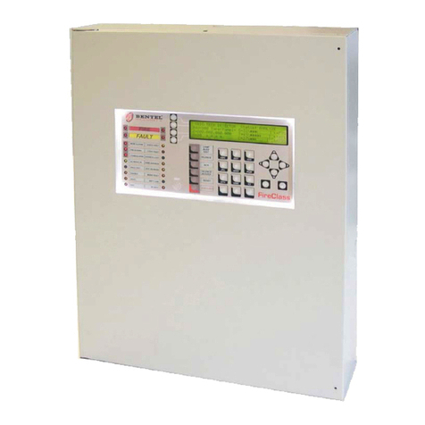
Bentel FireClass FC500 User manual
Bentel
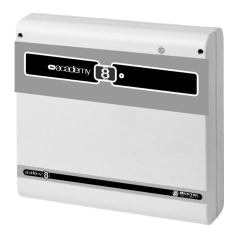
Bentel academy 4 User manual

Bentel
Bentel Omnia User manual
Popular Control Panel manuals by other brands
IDenticard
IDenticard 9000 Series Converting instructions
XYZ Machine Tools
XYZ Machine Tools ProtoTRAK RMX Safety and Quick Start guide
Observer
Observer TSTAT0201CW installation manual
AERMEC
AERMEC FMT 20 AW Use and installation manual
Intermatic
Intermatic T21000R SERIES Installation, operation & service manual
Radionics
Radionics D279A user guide
