Bergstrom Bycool green Series User manual
1001249409
F-4218 rev.01
SLIM FIT
Instrucciones de Montaje ES Spanish
Mounting Instructions EN English
Instructions de Montage FR French
Montageanweisungen GE German
Istruzioni di Montaggio IT Italian
MERCEDES ACTROS MP4
(FR) EURO 6
®
IATF 16949
Calidad en
Automoción
ISO 9001
Empresa
Registrada

2
SLIM FIT
ES
®
!
Atención
Al instalar el equipo de aire acondicionado en el techo
se debe proteger la parte superior de la cabina con un
paño o manta protectora para evitar posibles arañazos.
Al instalar Slimt en el techo hay que tener en cuenta
que, normalmente, las cabinas que vienen provistas de
escotilla, tienen una estructura suciente para soportar
el peso del equipo. Sin embargo, cuando no ocurra así y
sea necesario realizar corte en el techo o incluso si en el
caso de llevar escotilla el material no es lo sucientemente
resistente (caso de techo de bra, plástico, etc...) es el
instalador el que debe decidir, bajo su responsabilidad,
sobre la necesidad de reforzar el techo para evitar
posibles deformaciones, roturas, entradas de agua, etc...
habilitando los medios para que esto no ocurra.
!
Atención
Si durante el montaje el equipo se inclina o se
abate la cabina con el equipo montado, se deberá
esperar un mínimo de 60 minutos, desde que
el quipo quede horizontal, antes de ponerlo en
marcha.
Herramientas
Juego de Llaves Torx
Juego de Llaves Allen
Llave ja 13, 14, 22
Tijeras
Flexómetro
Destornillador
Documentación incluída
Instrucciones de montaje 1001249409
Manual del usuario 220AA35378
Diagnosis de averías 220AA35379
!
Advertencias
!
El personal instalador debe poseer una formación
suciente en Aire Acondicionado de vehículos.
!
dirna Bergstrom, s. l. queda exenta de
responsabilidad si se producen averías que procedan
de una inadecuada manipulación o instalación
del equipo, o por modicaciones y sustituciones
efectuadas sin nuestra expresa autorización por
escrito.
!
Equipo precargado con gas refrigerante R-134a.
(No manipular el circuito de gas refrigerante).
!
Véase procedimiento de garantía del producto
incluido en Diagnosis de Averías.
!
Véase Manual de Usuario del equipo para el correcto
funcionamiento del mando a distancia y del panel de
control.
!
Al nalizar la instalación se debe entregar al usuario:
Manual del Usuario, Garantía y Diagnosis de
averías.
!
El equipo no cumple con la normativa ADR.
Recomendaciones
Para el montaje
• Antes de iniciar el montaje leer las instrucciones y
seguirlas durante el proceso de instalacion.
• Usar las herramientas adecuadas para cada
operación.
Electricidad
• Desconectar la llave de contacto.
• Desconectar la batería antes de empezar el montaje.
• Asegurar el conexionado de los componentes
eléctricos, vericando su correcto encaje.
Simbología
Frágil
Atención corte!
Riesgo eléctrico

SLIM FIT
3
ES
®
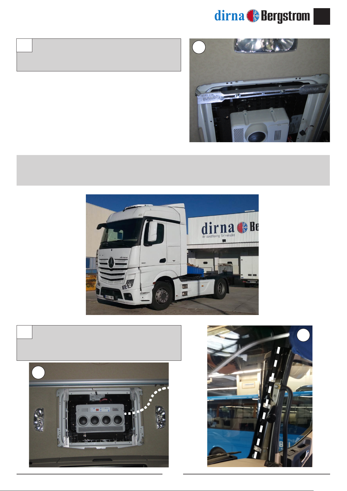
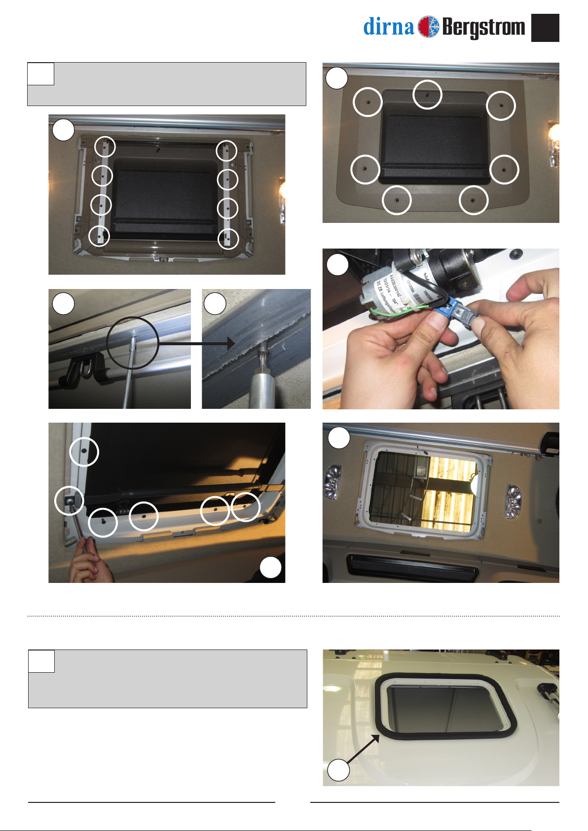
Desmontar escotilla y los elementos de jación y
entregar éstos al cliente.
11
1
1
1
1
1
1
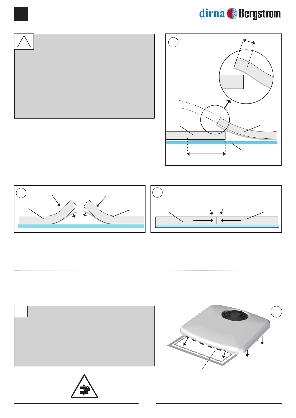
Pegue la junta EPDM 30x15 alrededor del hueco
escotilla (mirar detalle para cortar los bordes
nales de la unión de la junta).
2
2
4
SLIM FIT
ES
®
Posicionar el equipo sobre la junta introduciendo
el panel interior de distribución en el hueco de
escotilla.
¡Atención! Al colocar el equipo sobre el
hueco escotilla, verificar que las salidas
de desagüe no queden obstruidas por la
junta EPDM.
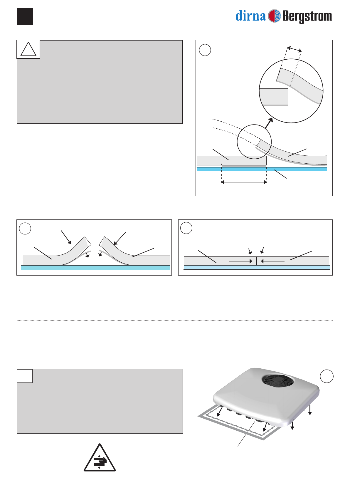
3
Escotilla
Junta
Junta
Eliminar
Junta
Junta
Junta
Techo cabina
Junta
100 mm Aprox. (papel protector)
15 mm
A
COMO CORTAR LA JUNTA EPDM PARA
EVITAR FILTRACIÓN DE AGUA EN LA
CABINA
A- Pegar la junta, manteniendo 100 mm de
papel protector por cada lado.
B- Quita los dos piezas de papel.
C- Pegue presionado ambos nales.
!
BC
3
SLIM FIT
5
ES
®
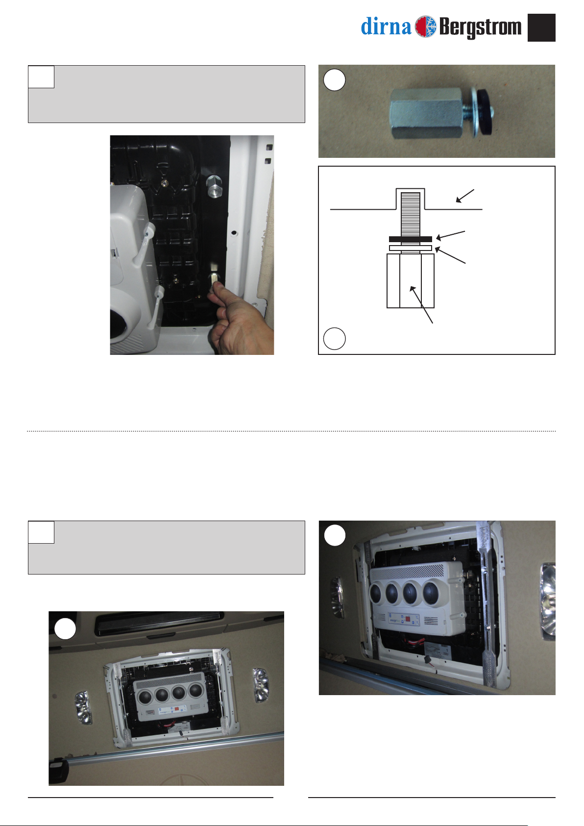
Colocar soportes de jación con arandela
plana, arandela grower y tornillo M8/125x45
sin apretar.
55
5
4
4Hexágono M8/125x40
Arandela goma
Base
Arandela plana
Roscar (4) hexágonos M8/125x40 con arandela
goma, arandela plana en insertos de la base y
apretar con un par de apriete de 12,7±10 Nm.
4
6
SLIM FIT
ES
®
Roscar (2) hexágonos M6 L=19 en la parte
trasera del equipo (sentido marcha) con
arandela de goma y arandela plana y apretar
con un par de apriete de 4,75±10% Nm.
Roscar (2) hexágonos M6 L=68 en la parte
delantera del equipo (sentido de la marcha)
con arandela de goma y arandela plana y
apretar con un par de apriete de 4,75±10%
Nm.
6
7
8
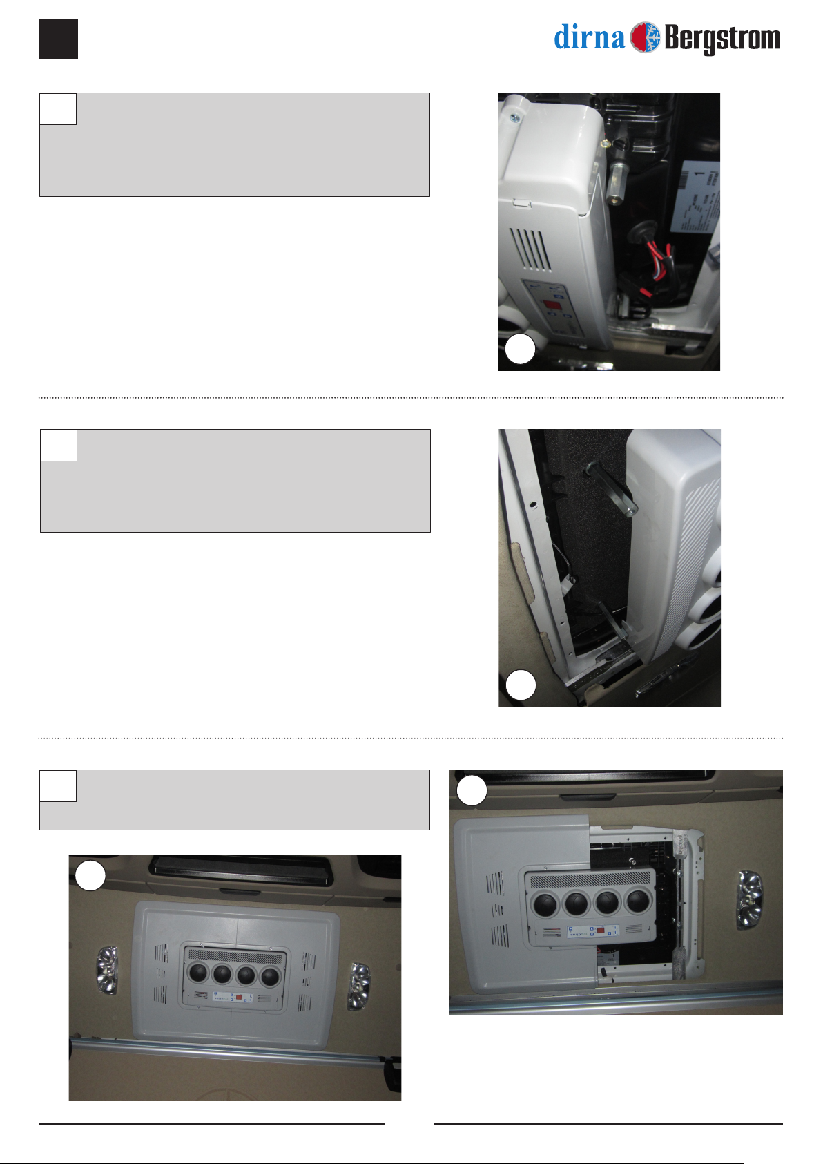
8
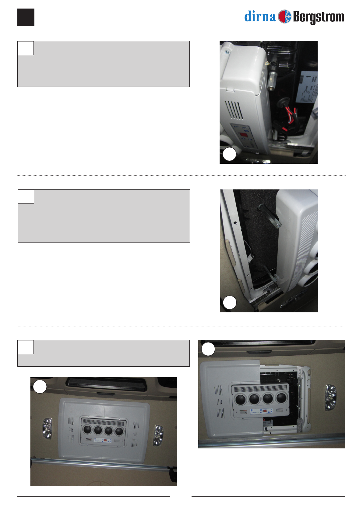
Presentar consola y mover el equipo. Tomar
como referencia el riel de la cortina.
8
6
7
SLIM FIT
7
ES
®
Retirar consola y apretar tornillos M8/125x45
hasta hacer tope con los hexágonos para jar
el equipo.
99
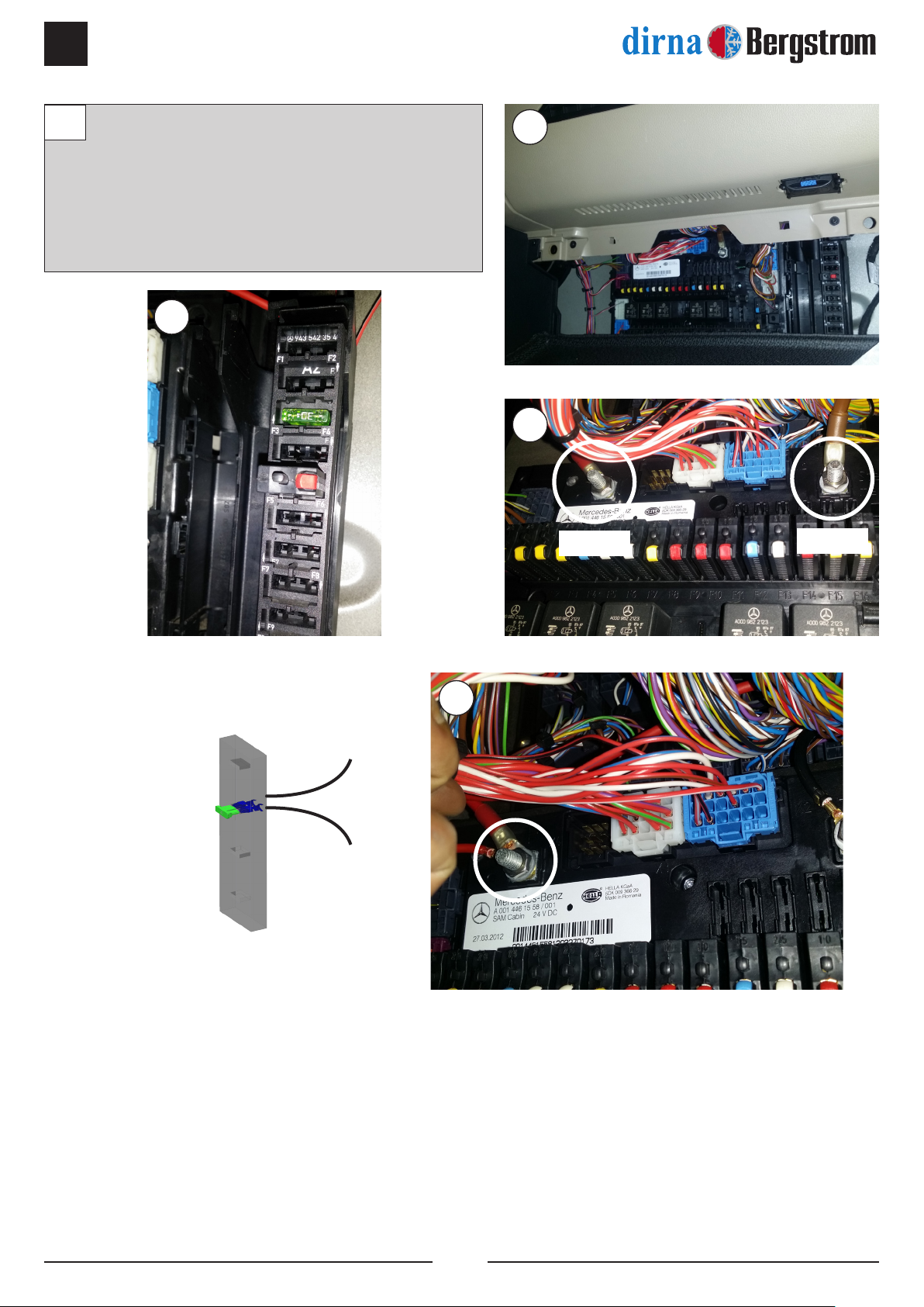
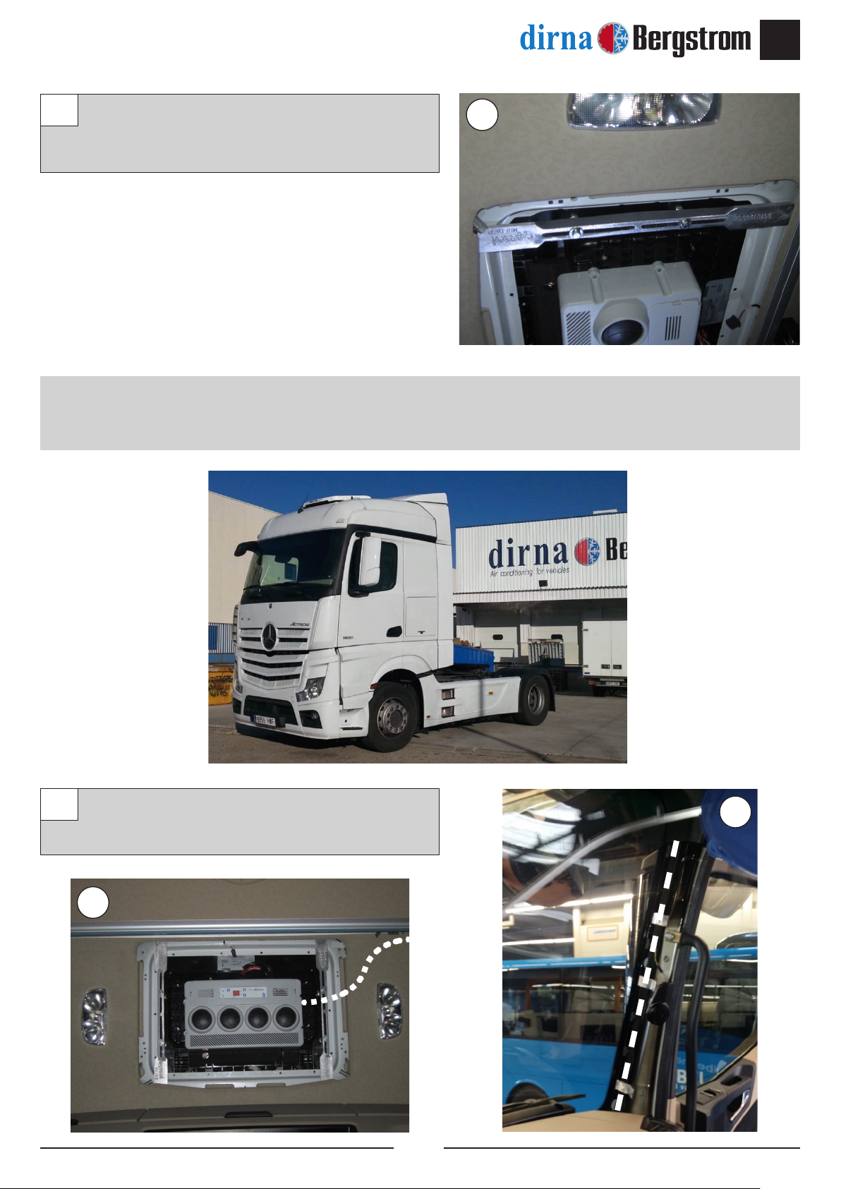
INSTRUCCIONES DETALLADAS SOBRE
CONEXIÓN CABLEADO ALIMENTACIÓN
Llevar cableado por dentro de tapizado con
ayuda de una gruía y llevarlo hasta la bajante
del lateral.
10 10
10
8
SLIM FIT
ES
®
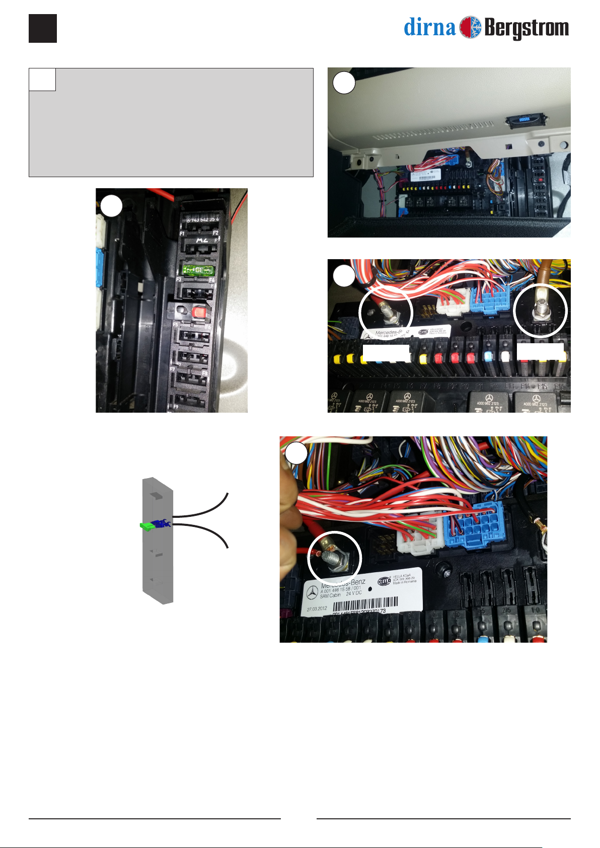
Llevar cableado hasta caja de fusibles y cortar
a medida deseada, después, grapar terminal
suministrado y conectarlo en caja de fusibles
posición F3, F4. Poner fusible 30A suministrado.
Grapar el otro extremo y llevar cableado hasta
positivo. Llevar cable negro (negativo) a masa.
11 11
11
11
11
positivo masa
Grapar
terminales
R1
R2
Fusible 30A

SLIM FIT
9
ES
®
(2) M6 M-H L=19
(2) M6 M-H L=68
Arandela
plana Ø 6
Arandela plana Ø 6
Arandela goma
Arandela goma
VISTA EXPLOSIONADA LATERAL HASTA LA FIJACIÓN DE LAS CONSOLAS
VISTA EXPLOSIONADA HASTA LA FIJACIÓN DE LOS SOPORTES
Junta EPDM 30x15
Techo cabina
Tapizado
Soporte jación
8/125x458/125x45
M8 M-H L=40
M8 M-H L=40
Arandela goma
Arandela plana Ø 8
Junta EPDM 30x15
Techo cabina
Tapizado
Consola
Soporte jación
M8/125x45
6/100x15 allen
Panel interior de distribución de aire

10
SLIM FIT
ES
®
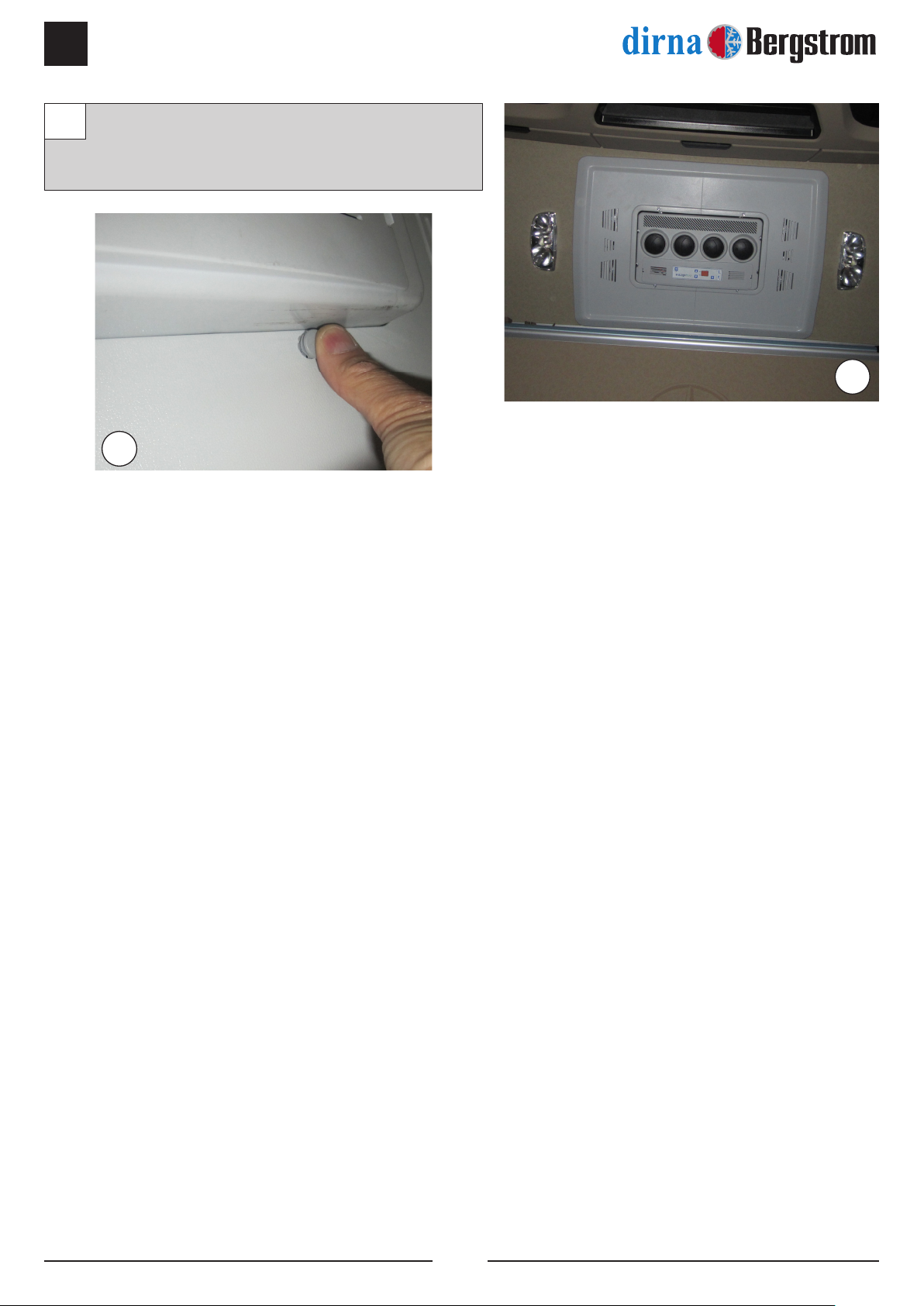
Volver a montar consola con (4) tornillos
6/100x15 allen y colocar después (4) tapón
embellecedor.
12
12
12
SLIM FIT
11
ES
®
N
N
N
N
Na
N
Az
R
N
B
Az
B
M
M
R B
B
Az
N
R
-
+
+
N
R
R
M
F
D
C
P
T
-
+
+
F
D
C
P
T
R
Az
M
NR
NR
RR
N
M
RB
N
Az
Na
R
A
N
R N
R
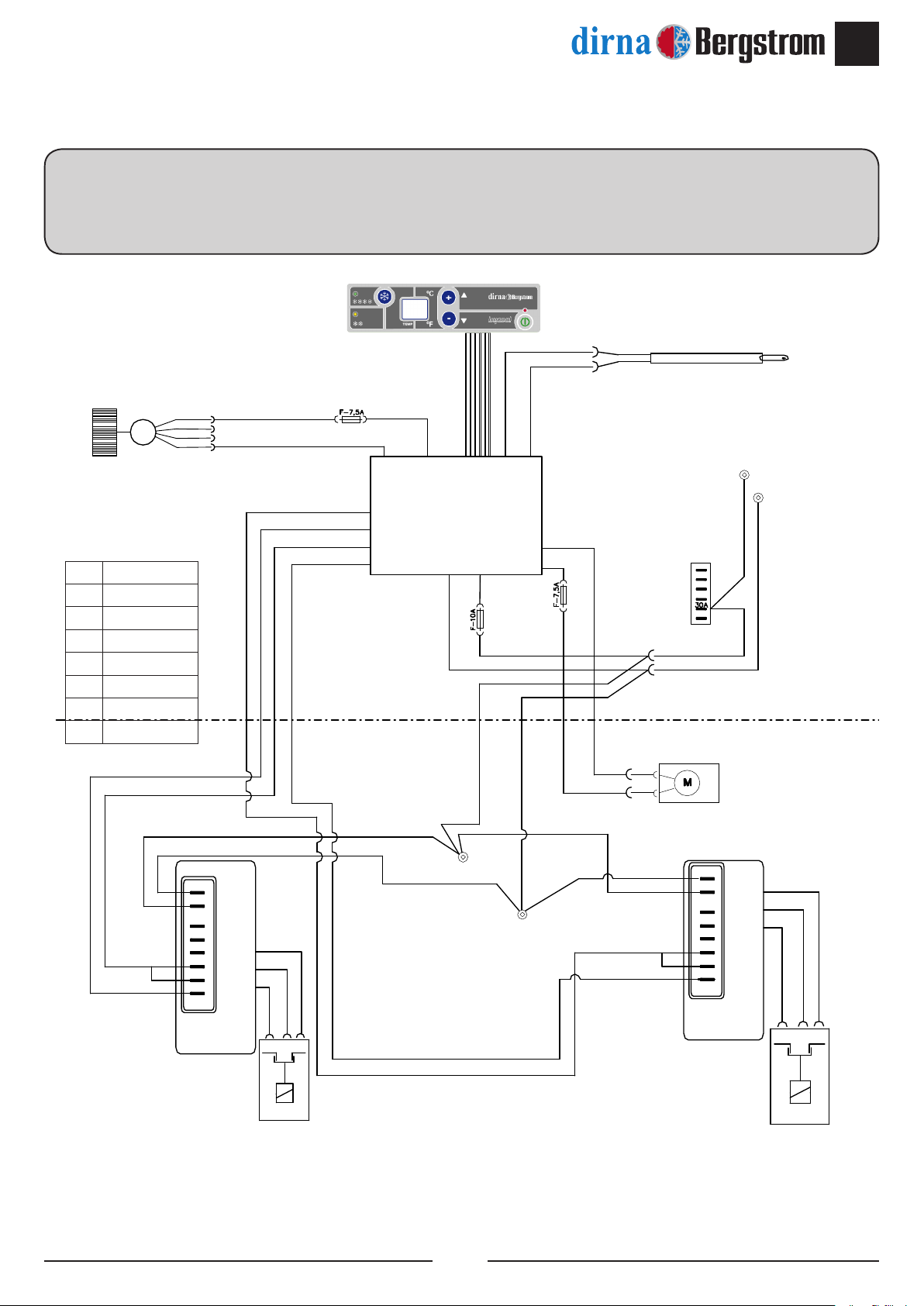
Esquema eléctrico
¡AVISO IMPORTANTE!
Precaución de no invertir las polaridades al conectar la alimentación en el equipo. Si esto sucediera el panel
de control no se enciende y el equipo no funciona.
Az Azul
N Negro
RRojo
V Verde
B Blanco
A Amarillo
Na Naranja
M Marrón
Sensor
aire de retorno
Soplador
centrífugo
2,6 Amp.
ntc 15kΩ 25º
2,9 Amp.
PWM.
Control
electrónico
Consumo
30mAmp
Ventilador
del condensador
Control
1º Compresor
Control
2º Compresor
1 Compresor2 Compresor
Conexión
positivo
Caja
fusibles
F3, F4
Conexión
negativo
12
SLIM FIT
EN
®
!
Warning
When installing air conditioning equipment on roof, the
upper cabin part must be protected with a cloth or a
protective blanket to avoid possible scratches. When
installing Slimt on roof, take into account that, normally,
cabins equipped with a hatch have a strong enough
structure to hold equipment weight. However, if it is not
the case and it is necessary to carry out a cut in the roof
or, although it has a hatch, the material is not resistant
enough (if roof is made of bre, plastic, etc...), it is the
installer who will have to decide, under his responsibility,
if it is necessary to reinforce the roof to avoid possible
deformations, breaks, water entries, etc., habilitating the
means required to stop it from occurring.
!
Warning
If the unit slants during assembly, wait for at
least 60 minutes with the unit in horizontal
position before starting it up.
Tools
Torx wrenches set
Allen wrenches set
Open-jawed spanner 13, 25
Scissors
Flexo-meter
Screwdriver
Documentation included
Mounting instructions 1001249409
User’s guide 220AA35378
Troubleshooting 220AA35379
!
Warnings
!
The installing personnel must have a sufcient
training in vehicles air conditioning.
!
dirna Bergstrom, s. l. shall not be responsible for
breakdowns or damages coming from an inadequate
handling or installation of the equipment or from
modications and substitutions carried out without
our express and written authorisation.
!
Equipment pre-charged with refrigerating gas.
(Do not handle refrigerating gas circuit).
!
Please see product warranty procedure included in
Troubleshooting diagnosis.
!
Please see equipment User’s Guide for its correct
functioning of the remote control and control panel.
!
Once installation is nished, the following documents
must be handed over to the user: User’s Guide,
Warranty and Troubleshooting Diagnosis.
!
The unit does not comply with ADR regulations.
Assembly
Recommendations
• Before starting assembly, please read instructions
and follow them during installation process.
• Use the adequate tools for each operation.
Electricity
• Disconnect ignition key.
• Disconnect battery before starting assembly.
• Make sure electric components are securely
connected, checking their correct tting.
Symbology
Fragile
Beware of cuts!
Electrical hazard
SLIM FIT
13
EN
®
Take down the hatch and the fastening elements,
and hand them over to the customer.
11
1
1
1
1
1
1
Attach the EPDM 30x15 seal around the hatch
gap (see the details to cut the ends of the seal
joint).
2
2
14
SLIM FIT
EN
®
Position the unit on the seal, introducing the
interior distribution panel in the hatch gap.
Caution! When positioning the unit above
the hatch gap, check that the wastewater
run-offs are not blocked by the EPDM
seal.
3
Hatch
Gasket
Gasket
Remove
Gasket
Gasket
Gasket
Cabin roof
Gasket
100 mm Approx. (protection paper)
15 mm
A
HOW TO CUT EPDM GASKET TO AVOID
WATER FILTRATION INTO THE CABIN
A- Glue gasket, keeping 100 mm of protection
paper at each side.
B- Remove the two pieces of paper.
C- Glue by pressing both ends.
!
BC
3

SLIM FIT
15
EN
®
Position the fastening mounts with a at
washer, grower washer and M8/125x45 screw,
without tightening.
55
5
4
4Hexagon M8/125x40
Rubber washer
Base
Flat washer
Screw (4) M8/125x40 hexagons with rubber
washer, at washer in the base inserts, and
tighten with a torque of 12.7±10 Nm.
4
16
SLIM FIT
EN
®
Screw (2) M6 L=19 hexagons on the rear of
the unit (direction of travel) with rubber washer
and at washer, and tighten with a torque of
4.75±10% Nm.
Screw (2) M6 L=19 hexagons on the rear of
the unit (direction of travel) with rubber washer
and at washer, and tighten with a torque of
4.75±10% Nm.
6
7
8
8
Position the console and move the unit. Use the
curtain rail as a reference.
8
6
7
SLIM FIT
17
EN
®
Remove the console and tighten M8/125x45
screws until it comes up against the hexagons
in order to secure the unit.
99
DETAILED INSTRUCTIONS ON
POWER CABLE CONNECTION
Run the cables inside the upholstery to the side
downpipe with the help of a guide.
10 10
10
18
SLIM FIT
EN
®
Run the cables to the fuse box and cut at the
required measurement, then clamp the supplied
terminal and connect it to fuse box position F3
and F4. Insert the supplied 30A fuse. Clamp the
other end and run the cable to positive. Run the
black cable (negative) to mass.
11 11
11
11
11
positive mass
Clamp
terminals
R1
R2
30A Fuse

SLIM FIT
19
EN
®
EXPLODED VIEW THROUGH TO MOUNT FASTENINGS
30x15 EPDM seal
Cabin roof
Upholstery
Fastening mount
8/125x458/125x45
M8 M-H L=40
M8 M-H L=40
Rubber washer
Ø8 Flat washer
(2) M6 M-H L=19
(2) M6 M-H L=68
Ø6 Flat
washer
Ø6 Flat washer
Rubber washer
Rubber washer
EXPLODED SIDE VIEW THROUGH TO CONSOLE ATTACHMENT
30x15 EPDM seal
Cabin roof
Upholstery
Console
Fastening mount
M8/125x45
6/100x15 allen
Interior air distribution panel
20
SLIM FIT
EN
®
Replace the console with (4) 6/100x15 Allen
screws and then position (4) decorative
caps.
12
12
12
This manual suits for next models
1
Table of contents
Languages:
Other Bergstrom Automobile Accessories manuals

Bergstrom
Bergstrom bycool green line COMPACT 1.4 IVECO User manual

Bergstrom
Bergstrom eCoolPark 1.0 12V User manual

Bergstrom
Bergstrom LITE Operating instructions

Bergstrom
Bergstrom SLIM FIT Instruction Manual

Bergstrom
Bergstrom SLIMFIT Operating instructions

Bergstrom
Bergstrom NITE Plus 9000i User manual


