Berner BGI40 User manual

operating instructions
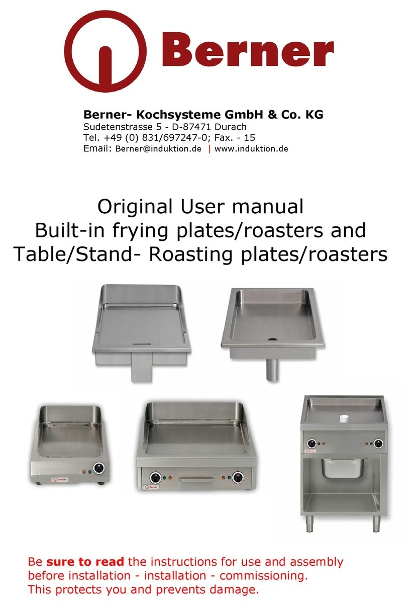
Installation-Induction fryingplates
from - Y.O.M. 2014
BGI40, BGI60, BGI80
*Options: GSG1, GSG2, ESB, EOI, ESRTI
Be sure to read the instructions for use and assembly
before installation - installation - commissioning.
This protects you and prevents damage.
Berner- Kochsysteme GmbH & Co. KG
Sudetenstrasse 5 - D-87471 Durach
Tel. +49 (0) 831/697247-0; fax. - 15
enamel: Berner@induktion.de | www.induktion.de

side 1 from 34 08.11.2014
Ver. 2.9 © Berner cooking systems 2014
table of contents
table of contents ....................................................................................................................... 1
Safety...................................................................................................................................... 3
Safety regulations ..................................................................................................................... 4
Description of Hazard Symbols ................................................................................................. 4
Dangers in case ofnon-observance of safetyregulations ............................................................... 4
Safe use................................................................................................................................ 4
Improper operation................................................................................................................. 5
Changes / use of spare parts ................................................................................................... 5
Monitoring of the heating zone ................................................................................................. 6
Noise .................................................................................................................................... 6
General.................................................................................................................................... 6
application............................................................................................................................. 6
Product .................................................................................................................................... 6
products................................................................................................................................ 6
specifications ............................................................................................................................ 6
Operation and control .......................................................................................................... 6
Technical device data ........................................................................................................... 6
Functional conditions............................................................................................................ 6
Power tabe 1 channel (single generator BIPS) ............................................................................ 7
Power table 2 channel (double generator BIPDS)........................................................................ 7
installation ............................................................................................................................... 7
Electrical data of the devices.................................................................................................... 7
Devices by power (5 kW- BIPS) ............................................................................................. 7
Devices by power (10 kW- BIPDS) ......................................................................................... 7
Installation pre-conditions ....................................................................................................... 8
Installation regulations for the installation model..................................................................... 8
commissioning .......................................................................................................................... 9
assembly............................................................................................................................... 9
Devices on and off switch ...................................................................................................... 10
Standby function (optional) ................................................................................................... 10
How to use the standby function.......................................................................................... 10
Control with potentiometer and 4-digitr display .................................................................... 10
Control with touch control panel ............................................................................................. 11
Heating states (function key inactive) .................................................................................. 11
function key: ....................................................................................................................... 12
Heating states (function key active) ..................................................................................... 12
Residual heat indicator.......................................................................................................... 12
service................................................................................................................................... 13
Cooking process ................................................................................................................... 13
comfort ............................................................................................................................... 13
Software Version .................................................................................................................. 13
Meaning Decimal Point: ...................................................................................................... 13

side 2 from 34 08.11.2014
Ver. 2.9 © Berner cooking systems 2014
Decommissioning .................................................................................................................... 14
Error detection........................................................................................................................ 14
troubleshooting....................................................................................................................... 15
Overview Error messages on display ....................................................................................... 16
cleaning ................................................................................................................................. 17
Care ...................................................................................................................................... 17
Insertion of the frying plate: .................................................................................................. 17
warranty ................................................................................................................................ 19
Repair during the warranty period .......................................................................................... 19
maintenance........................................................................................................................... 19
disposal ................................................................................................................................. 19
Declaration............................................................................................................................. 20
List of spare parts ................................................................................................................... 22
BIPS Generator .................................................................................................................... 22
BIPDS Generators ................................................................................................................ 24
Technical documentation.......................................................................................................... 26
Device view (example: BGI40)............................................................................................... 26
Installation example ............................................................................................................. 26
airflow ................................................................................................................................ 27
Observe installation regulations ................................................................................................ 28
Installationsvorschriften ................................................................................................... 28
Additional installation requirements for the installation model ......................................... 29
Attention points for remote coil (coil - generator separated) ............................................ 29
Installation instructions for the installation of Berner ................................................................... 30
Sensor keypads with support frame (Ver. A) ............................................................................ 30
Installation instructions for flush-mounted installation ................................................................. 31
(Ver. A2) by Berner Sensor keypads ....................................................................................... 31
Installation instructions for flush-mounted installation ................................................................. 32
(Ver. B) by Berner Sensor keypads ......................................................................................... 32
Installation instructions for flush-mounted installation ................................................................. 33
(Ver. B) from display 4 digits (version I) ................................................................................. 33

side 3 from 34 08.11.2014
Ver. 2.9 © Berner cooking systems 2014
Safety
Read this guide carefully. Keep the instructions for use and assembly for later use
or for subsequent owners. Check the device after unpacking. Do not connect in the
event of transport damage. Record the damage in writing and call the customer
service, otherwise the warranty claim will not be waived. The installation of the
device must be carried out in accordance with the attached installation instructions.
Use the device only for preparing food. Supervise the device during operation. Use the device
only indoors. Do not use hob covers. They can lead to accidents, e.B. due to overheating,
inflammation or cracking materials. Do not use unsuitable protective devices or child protection
screens. They can lead to accidents. This device is not intended for operation with an external
timer or remote control.
If you are wearing a pacemaker or other electronic body help,be careful when you are in front
of a switched-on induction hob. Check with your doctor or medical device manufacturer for
compliance or possible intolerance.
Fire!
-Hot oil and fat ignite quickly. Never leave hot oil and grease unattended. Never extinguish
a fire with water. Switch off the cooking place. Carefully suffocate flames with lid,
extinguishing blanket or similar.
-The cooking places get very hot. Never place combustible objects on the hob. Do not store
any items on the hob.
-The device gets hot. Store non-flammable objects or spray cans in drawers directly under
the hob.
Risk of combustion !
-The heating zone(s) and its surroundings, in particular a possible rimmumen, become hot.
Never touch the hot surfaces. Keep children away.
-The heating zone heats, but the display does not work. Switch off the fuse in the fuse box.
Call customer service.
-Metal objects get hot very quickly onthe heating zone(s). Never place metal objects, such
as .B knives, forks, spoons and lids on them.
-After each use, turn off the device with the main switch. Do not wait for the hob to turn off
automatically.
Risk of electric shock !
-Improper repairs are dangerous. Only acustomerservice technician trained by us is allowed
to carryout repairs and replace damaged connecting lines. If the device is defective, pull the
power plug or switch off the fuse in the fuse box. Call customer service.
-Invading moisture can cause an electric shock. Do not use a high-pressure cleaner or steam
cleaner.
-A defective device can cause an electric shock. Never turn on a defective device. Pull the
power plug or turn off fuse in the fuse box. Call customer service.
-Jumps or fractures in the glass ceramic can cause electric shocks. Switch off the fuse in the
fuse box. Call customer service.
Damage!
-The device is equipped with a blower at the bottom. Observe the installation instructions
for the air duct.
attention!
-Rough pot and pan bottoms scratchthe surface.
-Never place empty cooking vessels onthe heating zone(s). This could lead to damage.
-Do not place hot pots or pans on the control panel, displays or hobs. This could lead to
damage.
-If hard and pointed objects fall or actonthe surface, damage may occur.
-Aluminum foil and plastic vessels melt on hot stoves. The heatof stove protection film on the
heating zone(n) is not recommended.
-Never cool or clean with cold water or ice cubes. This leads to damage.

side 4 from 34 08.11.2014
Ver. 2.9 © Berner cooking systems 2014
Safety regulations
Description of Hazard Symbols
General danger symbol
Failure to comply with safety regulations
means danger ( injuries )
This symbol warns of dangerous tension.
(Figurine 5036 of IEC 60417-1)
This symbol warns against non-ionizing electromagnetic
radiation. (Figurine 5140 of IEC 60417-1)
Danger symbols directly attached to the device must be followed and readability
must be ensured at all times.
Dangers in case ofnon-observance of safetyregulations
Failure to comply with the safety regulations can lead to danger to persons, the environment
and to the inductionsystemitself. In the event of non-compliance with the safety regulations,
there is no right to claim any damages.
In detail, failure to observe the following risks may result in the following risks
( Examples):
-Danger to persons due to electrical causes
-Danger to people from overheated pans
-Danger to persons due to overheated storage area
Safe use
The safety provisions of this manual, the existing national rules on electricity to prevent
accidents and any internal working, application andsafetyregulations must be followed.
attention
In case of improper use
may cause minor injuries or
damage to property!
attention
The user manual must be read before using or
maintaining the device.

side 5 from 34 08.11.2014
Ver. 2.9 © Berner cooking systems 2014
-attention! Do not place hot pots or pans on the heating zone(s) on the control panel,
indicators or hob frame. Ignoring this notice will damage the pots and equipment. Effect in
ignoring: Pots are welded together, burning the joint material by heat of the pots and thus
destroying the seal, leading to penetration of moisture and grease and can thus lead to the
defect of the device. Defect of the displays or control panels.
-If the frying plate is torn or broken, the inductiongerät mustbe switched off and disconnected
from the electrical supply. Do not touch any parts inside the induction.
-The heating zone(n) is heated by induction. To avoid injuries (burns), do not touch the
heating zone(s).
-Please be wareify against hot food and liquids.
-PLEASE NOTE: Warning of possibly slippery ground in the vicinity of the device. This can
lead to injuries.
-Turn off the heating zone if you don't needit. This prevents the heating process from
automatically. Thus, unattended heating is avoided, i.e. a person whowants to use the
inductiongerät must start the heating process by switching on the device or by turning the
power controller to 'ON'.
-Do not use the heating zone(s) as a shelf!
-Do not place paper, cardboard, fabric, etc. on the heating zone(s)as it mayignite. Aluminium
foils and plastic vessels must not be placed on the hot surfaces.
-Care must be taken to ensure that during the operation of the device, items worn by the
user, such as.B rings, watches, etc., can become hot when they come close to the frying
surface.
-After use, the device must be switched off by means of its control and/or control device.
Device does not switch offautomatically.
-Do not place credit cards, phone cards, cassettes or othermagnet-sensitive items on the
heating zone(s).
-The inductiongerät has an internal air cooling system. Avoid obstructing the air supply and
air outlet zone with objects (e.B. fabric). This would cause overheating and therefore the
device's shutdown.
-Avoid the entry of liquids into the device and overflow water or cooking material over the
edge of the frying area. Do not clean the device with a water jet.
Improper operation
The functionality of the inductiongerätit can only be guaranteed if used correctly. The limit
values in accordance with the technical data may not be exceeded or exceeded under any
circumstances.
Changes / use of spare parts
Contact the manufacturer if you intend to make changes to the device. To ensure safety, use
only original spare parts and accessories approved by the manufacturer. When using non-
original components, all liability for follow-up costs expires. When disassembly, testing or
repairs, pay attention to the stability of the device.
Attention! When replacing spare parts, the induction device must be "visibly tt" from the
power supply.

side 6 from 34 08.11.2014
Ver. 2.9 © Berner cooking systems 2014
Monitoring of the heating zone
The heating zone is monitored by a temperature sensor located underthe frying surface. The
energy supply is stopped when the selected temperature is reached. At a higher temperature,
thedevice does not transfer energy back intothe frying surface until the temperature has fallen
below the selected value.
Noise
The fans of the cooling are audible, but switch off again in between.
General
This manual contains basic information that must be observed during assembly, application
and maintenance. It must be read completely by the installer and the operator before
installation and commissioning, and must always be located near the cooking station for a look-
up.
application
The inductiongeräte are used for preparing meals. They can be used for frying,keeping warm,
grilling etc. of food.
Product
products
-Compact modular design
-Easy operation via rotary knob and digital 4-digit display
-Compact power electronics enable easy and safe operation
-Max operational safety thanks to various protection and monitoring functions
-Continuous temperature with electronic overtemperature protection of the power part.
specifications
Operation and control
Lamp "Operation" 2V DC/approx. 10mA (LED Green)
Power Controller - Potentiometer0Ohm - 10kOhm
Digital display "Power and error display" 2.8V DC/approx. 60mA (red)
Lamp "Operation" green (devices with main switch)
Technical device data
ModelHeating zone(s)external dimensions in B x T x H
Externalframe in W x T x H
BGI401400 x 600 x 120 mm400 x 600 x 20 mm
BGI602600 x 600 x 120 mm600 x 600 x 20 mm
BGI802800 x 600 x 120 mm800 x 600 x 20 mm
Devices Coil VoltageType GeneratorPower Weight
BGI40 300x460 mm400V/3"/N/PE BIPS5400V/3"/PE 5.0 kW30.40 kg
BGI60 260x460 mm400V/3/N/PE BIPDS400V/3/PE 10.0 kW-- kg
BGI80 350x460 mm400V/3/N/PE BIPDS400V/3/PE 10.0 kW -- kg
Functional conditions
omax. tolerance of mains voltage nominal voltage+5%/-10%
oFrequency50 / 60 Hz
oProtection class in delivery state with module IP 21
oProtection class in delivery state with separate generator (GSG1/2) IP 11

side 7 from 34 08.11.2014
Ver. 2.9 © Berner cooking systems 2014
Power tabe 1 channel (single generator BIPS)
Power table 1 phases generator / 2 phase generator
Sw1
4 5
Type 230V
Current [A]
Power[kW]
Type 400V
Current [A]
Power[kW]
0 0
8
1.8
7.5
3.0
0 1
10.9
2.5
8.75
3.5
1 0
13.1
3.0
10.0
4.0
1 1
15.3
3.5
12.5
5.0
Power Table 3 Phases Generator
Sw1
4 5
Type 400V
Current [A]
Power[kW]
Type 230V
Current [A]
Power[kW]
0 0
5.10
3.5
7.5
3.0
0 1
7.25
5.0
8.75
3.5
1 0
10.2
7.0
10.0
4.0
1 1
12.3
8.5
12.5
5.0
Power table 2 channel (double generator BIPDS)
Power Table 3 Phases Generator
Sw2/3
1 2
Type 400V
Current [A]
Power[kW]
0 0
5.1 / 5.1
3.5 / 3.5
0 1
7.25 / 5.1
5.0 / 3.5
1 0
7.25 / 7.25
5.0 / 5.0
1 1
10.2 / 8.0
7.0 / 5.5
installation
Electrical data of the devices
Devices by power (5 kW- BIPS)
Induction cooktop 3-phase (voltage 400Volt +5% / -10%)
connection
colour
frequency
fuse
phase
Brown, Black, Grey or 1,
2, 3
50 Hz / 60 Hz
3 x 16A F (fast)
N
Blau or 4
Working
frequency 22-35
kHz
Tax security
-
Pe
Yellow/Green
Devices by power (10 kW- BIPDS)
Induction cooktop 3-phase (voltage 400Volt +5% / -10%)
connection
colour
frequency
fuse
phase
Brown, Black, Grey or 1,
2, 3
50 Hz / 60 Hz
3 x 16A F (fast)
N
Blau or 4
Working
frequency 22-35
kHz
Tax security
-
Pe
Yellow/Green
Installation environment
-Maximum ambient temperature
Storage >-20°C to +70°Cin Function>+5°C to +35°C
-maximum relative humidity
Storage> 10% to 90% in function> 30% to 90%

side 8 from 34 08.11.2014
Ver. 2.9 © Berner cooking systems 2014
Installation pre-conditions
The inductiongerät must be mounted in a straight surface by means of a mounting frame. The
air supply and outlet area must not be obscured. The installation area must allow a weight of
at least 100 kg. The mains disconnector must be easily accessible.
Installation regulations for the installation model
The following points must be observed:
-Check and make sure that the voltage of the main supply line matches that of the type plate.
-The electrical installations must comply with local building installation regulations. The
applicable national regulations of the electricity authorities must be complied with.
-The inductiongerät is equipped with a power cable, which can be connected to a socket with
the necessary plug.
-If incorrect current circuit breakers are used, they must be designed for a fault current of at
least I n=30mA.
-Prevent blocking of the air supply and air outlet zone by objects (fabric, wall, etc.)
-Avoid that hot ambient air is sucked in by the inductiongerät (several devices stand side by
side, devices stand one after the other, near frying tippers or ovens). Otherwise, a duct must
be used.
-The device has a suction filter. Nevertheless, you must ensure that no fat ambient air caused
by other applications can be sucked into the induction device (near fryers, grill plates or
fryers).
-The air intake temperature must be below +35°C.
-Operators must ensure that all installation, maintenance and inspection work is carried out
by approved personnel.
-The intake air must be channelled and fed directly to the fans via the supplied filter. The
intake cross-section should be at least 200 cm2 per electronic unit.
-Do not build a thermal short circuit. The exhaust air must not be sucked back in, otherwise
the device will become hotter and hotter.
-The installation must be checked for practicality. For this purpose, the maximum cooling
plate temperature must be determined. Measurements are made on the cooling plate base
plate below the induction coil. The temperature must not exceed 65°C in continuous
operation of at least 2 hours and 20°C ambient temperature.
-All INSTALLATION models must be fastened by means of an enclosed mounting frame.
-The power supply cable must be shielded in general and contacted cleanly on both sides.
-Provide the mains disconnector in such a way that a maximum of 5 times per day is switched
on and off.
-To maintain and replace parts, the device must be disconnected from the power supply. If a
pull of the plug is provided, clearly pointing out that the pulling of the plug must be done in
such a way that the operator can check from any seat to which it has access that the plug
is still removed. If this is not possible due to the design of the device or the installation, the
separation must be ensured with a locking in the separation position.
The inductiondevices areequipped with a cable and plug in accordance with national
regulations.
Make sure the plug is wired correctly:
For the electrical connection of the device, the legal
Regulations of the respective country!
attention
Incorrect voltage can cause the
Damage induction device
attention
The electrical connections must be carried
out by a specialist.

side 9 from 34 08.11.2014
Ver. 2.9 © Berner cooking systems 2014
commissioning
assembly
The inductiongeräte are equipped with a power cable. They must be connected to a wall socket
or junction box. The electrical installations must be carried out by approved installers in
compliance with specific national and local regulations. The installers are responsible for the
correct design and installation in accordance with the safety regulations. The warning and type
plates must be strictly followed.
Check and make sure that the voltage of the mains current and the device (type plate) match.
When installing this appliance in the immediate vicinity of a wall, partition walls, kitchen
furniture, decorative cladding, etc., it is recommended that these are not made of combustible
material; otherwise, they must be clad in suitable non-combustible, thermally insulating
material, and the fire protection regulations must be observed with the most care!
The inductiongerät must be in a clean, straight surface (table, combination, etc.) ebuilt up and
stand by its final destination. It must be installed in such a way that it cannot be moved. The
"installation requirements" must be met.
Remove all items from the heating zone(s). Check that the heating zone(s) is neither split nor
broken. If the heating zone is split or broken, immediately turn off the device and disconnect
the power plug.
Turn the main switch to the OFF position (0) before
Connect inductiongerät to the power grid.

side 10 from 34 08.11.2014
Ver. 2.9 © Berner cooking systems 2014
Devices on and off switch
Position OFF:Position ON:
'0' points to the mark ()'I' points to the mark (). οο
Power knob
(Depending on the model and option, various gags are used)
The number showing for marking marks the current position of the power knob.
Position OFF:
'0' points to the marking ()
Position A:P osition ON with standby:
Each position, which is used for the marking ()
displays. MIN (minimum) to MAX (maximum)
device. Before performing the functional test, the user must know how to operate the induction
devices.
Standby function (optional)
How to use the standby function
Rotate the gag to the green mark. When using this function by means of gags ()they activate
a predetermined value of 100°C. This feature helps to save energy. However, this also reduces
the heating times.
Control with potentiometer and 4-digitr display
With the gag, the temperature can be selected from 70-250°C. The display is as follows:
SHOULD temperature 70°C (point), actual temperature too low,
Heats: Point to the right of symbol
IS temperature 25°C (every 10 sec.), actual temperature too low,
Heats: point to the right of symbol
SHOULD temperature 70°C (point), actual temperature within +/-
2°C, Does not heat
IS temperature 105°C, actual temperature too high, does not
heat
H

side 11 from 34 08.11.2014
Ver. 2.9 © Berner cooking systems 2014
Control with touch control panel
Should/actual temperature (every 10 sec. IST temperature) Heating status (see table)
Increase temperature
(in 2C° increments, long press
for 10ér steps)
On/off switch
Lowering temperature
(in 2C° increments, long press
for 10ér steps)
Function key (see table)
Heating states (function key inactive)
Heating state "n"
The set set set temperature is still
not reached (if temperature is lower than
the setset temperature).
Heating ON
Heating state "H"
The set set set temperature is reached
(Is temperature equal to target temperature +/-
2C°). The device keeps thetemperature.
Heating state "u"
The set set temperature is lower than the IS
temperature (too hot).
Heating OFF

side 12 from 34 08.11.2014
Ver. 2.9 © Berner cooking systems 2014
function key:
With the function key, you can choose between two freely selectable temperatures
(e.B. working temperature, standby temperature). The heating states of the lower temperature
setting (standby temperature) are represented by " _ / / " .
Heating states (function key active)
Heating state "_"
The set set set temperature is still
not reached (if temperature is lower than
the set set set temperature). The device
Heats.
Heating state " .
The set set set temperature is reached
(Is temperature equal to target temperature +/-
2C°). The device keeps the temperature
Heating state " = "
The set set temperature is lower than the actual
temperature (too hot). The device
Don't heat.
Residual heat indicator
The device is switched off but still hot
(above 45C°) then the residual heat
display, which is represented by " - ".
attention
Injuries and burns
to avoid touching
the heating zone.

side 13 from 34 08.11.2014
Ver. 2.9 © Berner cooking systems 2014
service
Cooking process
The device is immediately ready for operation. The power indicator light lights up and the
digital display shows the desired, reached temperature or any error messages to. The
temperature is continuously selected bydeerenofing the temperaturecontroller or with the
sensor keypad.
Position MIN > 70°C minimum temperature
Position MAX> 250°C maximum temperature
Due to the following circumstances, the cook must be more attentive than when frying with
conventional cooking systems. The frying plate is in operating temperature in a short time and
can therefore be set into standby or deactivated when not in use.
comfort
The inductiongerät transmits energy to the heating zone(n)onlyif the temperature falls below
the selected value. By switching off with the rotary knob, the heatingprocess is stopped.
However, the device remains ready for operation (standby), only the pull-out of the power plug
or the power switch is switched off, making the device powerless.
Software Version
Starting up the generator
second
explanation
1
8. (Test of segments)
2
F or P (operation Fsequence or Pulse)
3
2. (Software version first digit)
4
1 (Software version second digit)
5
9 (Software version third digit)
Meaning Decimal Point:
AN = Operation
1 sec. pulse = limitation due to too high heat sink temperature
1/2 sec. pulse = limitation due to excessively high coils/pan temperature
1/4 sec pulse = power limit
1/10 sec. pulse = power limitation with not optimal Material
attention! Cookware must not be placed on the frying surface. Do not place hot pots or
pans on the control panel, displays or hobs. Ignoring this notice will damage the pots and
equipment. Effect of ignoring: Pots are welded together. Defect of the displays or control
panels.

side 14 from 34 08.11.2014
Ver. 2.9 © Berner cooking systems 2014
Decommissioning
If the inductiongerät is not in use, make sure that the main switch or temperatureknob is not
switched on unattended. If you do not use the device for a long time (several days), unplug or
turn off themain switch. Make sure that no liquid can get into the grigand do not clean the
device with liquid.
Error detection
The inductioncanonly be opened by approved and trained service personnel. If the heating
zone(s) is torn or broken, stop any work. The inductiongerät must be switched off immediately
and the power plug pulled out. Do not touch any parts inside the device.
attention
Do not open the induction device!
Dangerous tension!
WARNING: During cleaning or maintenance and when replacing parts, the equipment must
be disconnected from the power supply.

side 15 from 34 08.11.2014
Ver. 2.9 © Berner cooking systems 2014
troubleshooting
error
Possible cause
Measures taken by operators or
service personnel
No heating up
Power indicator lamp is OFF
No power supply
Check that the device is connected to the power
supply (power cable plugged in) or that the main
switch is turned on.
Rotary knob in OFF position
Turn the knob into one position
Main switch is OFF Turn the main switch into one position
Inductiongerät defective Contact your repair service supplier. Remove the
power plug from the power outlet.
Insufficient heating capacity
Power indicator lamp is
ON (lights)
Air cooling system is
disabled/blocked
Make sure that the air supply and export are not
obstructed/blocked.
Air filter is dirty.
Clean or replace filters.
Ambient temperature is too high
(the cooling system cannot keep
the cooker in normal operating
temperatures *2
Make sure that no hot air is sucked in. Reduce the
ambient temperature. The temperature must not
exceed 40°C / 110 °F.
A phase is missing
Check the backups.
Inductiongerät defective
Contact your repair service supplier. Pull the
power plug.
No reaction to turning the
temperatureknob
Temperaturregler defective
Heating capacity stops and off
within minutes.
Fan works
Air cooling system is
Blocked/disturbed
Make sure that the air supply and export are not
blocked.
Fan dirty
Cleaning fans
Heating capacity stops and off
within minutes. Fan is not
working.
Fan or fan monitoring defective Contact your repair service supplier. Pull the
power plug.
Heating capacity stops and
downs within minutes
(after longern, continuous
operating time)
Coil overheated,
Heating zone too hot.
Turn off the device, remove the pan and wait for
the heating zone to cool down.
No heating up Triggering the
Safety temperature limiters
Should the safety temperature limiter trigger and
switch off the heating, the re-entry may only take
place after the cause of the failure has been
determined and its elimination!
After the device has cooled down, the red
entriegelungs button canbe operated without
using force. Switching on again if the device is not
sufficiently cooled can damage the safety
temperature limiter s. Then, it is essential to
re-insert the protective cap to restore the
water protection.
*2)The ventilation begins to work when the temperature of the cooling plate exceeds 45°C. At
cooling plate temperatures above 70°C, monitoring automatically reduces performance to keep
the power part under normal operating conditions. The inductiongerät continues normally with
reduced maximum power.
If the mains connection line of this device is damaged, it must be replaced by the
manufacturer or its customer service or a similarly qualified person to avoid hazards.

side 16 from 34 08.11.2014
Ver. 2.9 © Berner cooking systems 2014
Overview Error messages on display
Short-circuit temperature sensor plate, plate temperature too low (smaller -50°C)
(every 5 sec when switched off)
Temperature plate too high, interruption temperature sensor on the plate >
260°C
No pan on the plate (too small pan on the plate)
Incorrect pan on the plate, short-circuit induction coil (a value to low)
Heat sink temperature >100°C or temperature sensor cooling plate short-
circuited
Heat sink temperature <-15°C or temperature sensor cooling plate interrupted
Missing or defective potentiometer: Incorrect value (greater than 10.75 kOhm)
Potentiometer to 0 position, residual heat indicator Hob temperature >45°C
signal for external display is missing (external display is set or SW1/3 switched
on) or
Temperature plate too high, interruption temperature sensor on the plate >
260°C
Switching on after power disconnection AC Phase L1 and L3 against zero < 150V
(If L2 fails, device with reduced power continues to run)
Failure of standard IO DEVICE 1 or 2 (possibly display print defective)
Warning: DC current greater than 350 mA (too many or incorrect fans)
Warning: Fan not connected or blocked (after start 5 sec, then every 10 sec for 1
sec.)
Overcurrent on induction coil, then 10 sec. pause. Device Off and Back On
Switch On

side 17 from 34 08.11.2014
Ver. 2.9 © Berner cooking systems 2014
cleaning
The housing and frying plate should be cleaned daily with commercially available means,
stubborn frying residues are soaked with water and a mild detergent for a few minutes when
the plate is still warm. After cleaning, plate well rinse and dry wipe. Lightly grease the steel
plate with fresh frying fat.
Scratching detergents, steel wool or scratching sponges must not be used as they
can damage the surface.
Professional maintenance of the frying plate requires regular cleaning, careful treatment and
service.
List of detergents for certain types of contamination:
Care
Insertion of the frying plate:
The frying plate surface must be thoroughly cleaned with water and detergent before
commissioning.
Attention: Please do not use a grill cleaner!
Then add oil to the surface and spread well with a cloth cloth. Heat the frying plate to approx.
200°C and wait until the oil gets a yellowish shimmer, i.e.
slightly deprecated. With the frying filler, remove the resined layer superficially. Perform this
operation 3x in total.
The duration of the pre-treatment is about 1 hour. An invisible patina has then formed on the
surface.
Now you can start to fill the frying plate. Before laying on the frying material, please apply
some oil again.
It should only be used with the supplied roast filler.
All other tools are unsuitable.
If, over time, frying residues have formed on the surface, wear them with the stainless steel
sponge. To prevent the sponge from burning, it should be used to push the sponge onto the
surface, the leading edge of the roasting filler.
(Please do not use water)
The inlet of the frying plate should be repeated daily in a shortened form.
Another tip to keep the frying plate as clean as possible during the operating time:
The smoke points of oils are 180-220°C. Depending on the oil, the frying temperature should
be
slightly below the smoke point.
When cleaning the frying plate after the operating time, switch off the frying plate and
approx. 15-20 min, if the frying plate still has residual heat, clean the plate only with water
and the stainless steel sponge using the frying filler and then
oil again.
WARNING: During cleaning or maintenance and when replacing parts, the equipment must
be disconnected from the power supply.
No liquids must enter the device!

side 18 from 34 08.11.2014
Ver. 2.9 © Berner cooking systems 2014

side 19 from 34 08.11.2014
Ver. 2.9 © Berner cooking systems 2014
warranty
You have purchased a high-quality product with a Bernese cooking appliance. As a
manufacturer, we provide a guarantee of one year from the date of purchase.
Repair during the warranty period
Please contact your specialist wholesaler.
maintenance
The user must ensure that all components relevant to safety are functional at all times. The
inductionSgmust be checked at least once a year by a trained technician from your supplier.
At least every 6 months, the air filter must be checked for contamination.
The inductioncanonly be opened by trained service personnel.
disposal
When the life of the inductionis terminated, itmust be disposed of professionally.
Avoid abuse:
The inductiondevice must not be used by unqualified persons. Avoid recommissioning the
device provided for disposal. The device consists of common electrical, electromechanical and
electronic components. No batteries are used. The user is responsible for the professional and
safe disposal of the deviceit.
Note on disposal
Devices intended for this purpose can be sent to us for disposal. Only enough
prepaid packages are accepted by us.
Delivery:
Berner- Kochsysteme GmbH & Co. KG
Sudetenstrasse 5 - D - 87471 Durach
Tel. +49 (0) 831/697247-0; fax. - 15
enamel: Berner@induktion.de | www.induktion.de
attention
Do not open the induction device!
Dangerous tension!
attention! For technical control, the induction device must be "visibly disconnected"
from the power supply.
This manual suits for next models
2
Table of contents
Other Berner Commercial Food Equipment manuals