Bespoke Infinity User manual

1
INSTALLATION
MANUAL
Infinity Stairlift
Rail
Carriage
Seat
Huddersfield • England

2
The information contained within this
manual has been designed for use by
Bespoke approved engineers who have
received the appropriate product training
in the following categories,
1. Product installation.
2. Testing and commissioning.
lt is also assumed that the person
using this manual will have the basic
knowledge and skills required in both the
mechanical and electrical aspects to apply
consideration and awareness for the safety
of themselves and others involving their
work.
The contents of this manual are in the
recommended order of placement, which
forms the full installation, and
commissioning
of this standard model.
INTRODUCTION

3
Introduction 2
Contents 3
Rail Preparation and Fixing 4-9
Carriage Preparation and Assembly 10-30
Calibrate and Program the Stairlift 31-35
Troubleshooting 36-39
Wiring Diagrams 40
Certificate of Conformity 41
Demonstration and Handover 42
Installation Tools 43
CONTENTS

4
Remove packaging and protective
wrapping from rail sections.
Position rail sections on staircase as per
Installation Drawing.
Insert the leg stanchions into the relevant
bases and approximately set the height
by tightening the 3 x grub screws on each
base. (Do not tighten too much as these
will need to be adjusted later)
RAIL PREPARATION
266.3
274.7
279.4
279.1
269.9
1147
2108.8
1161.6
265.1
274
269
266.2
267.9
265.4
263
255.7
302
48.9
259.9
269.1
274.1
268.8
261.7
273.5
259.5
265.5
272.2
267.5
275.5
278.9
264.5
14.1
984.7
910.6
1117.4
967.7
719.4
122.3
106.6
125.8
Riser 1
Riser 15
1
2
3
4
5
67
8
9
10
466.7
174.9
180.9
175.3
177.1
170.3
182.8
173.8
176.9
179.1
136.9
170
165.8
166.3
163
172.5
101
100
119.8
2565.6
312.9
499.9
515.6
526.4
442.1
442
442
507.1
489.6
124.2
Base/Stanchion
Number
Type Base
Height
Stanchion
Length
Total Height
1
New
205 ABF
280 312.87
2
New
165 450 499.87
3
New
204 450 515.62
4
New
204 450 526.37
5
New
100 400 442.06
6
New
100 400 442.04
7
New
100 400 442.04
8
New
100 400 442.02
9
New
165 450 507.07
10
New
165 450 489.59
Installation Drawing
RH EXT 180 - Standard Start and
Finish
A3
SHEET 1 OF 3
DWG:
TITLE:
Revision
DATE:
DO NOT SCALE DRAWING
UNLESS OTHERWISE SPECIFIED: DIMENSIONS ARE IN MILLIMETERS (mm)
ASSEMBLY BY:
SAGE ACCOUNT NO.
TYPE:
Model
Handing
Type
Swivel
Seat Type
Footrest
Extra Remotes
Controls
Remote Type
Region
Upholstery Colour
Surveyed By
Dispatch
Bend(s)
Rail Start
Rail Finish
Int' Landing
Int' Charge Point
Foot Covers
Rail Colour
Wall Brackets
Offset Footrest
Rail Length
Rail Sections
Bases to Kit
DRAWING BY:
1
Stairlift Specifications
10
No
7
8324.37
RAL 9010
No
No
N/A
N/A
Standard
Standard
2x90
Courier
Customer
Germany
Red
N/A
Recon
Recon
Recon
Manual
Right
BS 101
New
Standard
Square Ness
& U Bends
Vertical Height
O/B
-5/+15
I/B
-15/+5
Ride Quality
-10/+20
Upper Flights
Lower Flights
-/+2
-20/+20
-10/+20

5
Thread 2-core cable through lower tube of
each section of rail, working from top to
bottom.
Ensure a minimum of 150mm of cable at
each end.
RAIL PREPARATION

6
Assemble rail joints together working from
bottom to top of stairs.
Note: Offer top tubes first.
Apply grease to male part of joint.
Pins should be flush with stair side of rail.
Fit and tighten joint clamps
Using the installation drawing details:
Check top and bottom rail heights over
the corresponding steps.
Check rail angles
Check lower and upper rails are vertically
in line.
Adjust leg heights as required.
Ensure rail to wall measurements match
the Installation drawing.
RAIL FIXING

7
Secure plates to the staircase by the
following method:
Loosen grub screws on leg collar
Fix foot-plate with 3 screws (Figure 4)
Tighten screw to leg.
Repeat for each leg.
The following fixings are recommended:
Timber Staircase - 3 x 50mm screws.
Concrete Staircase -3 x 50mm screws & 3 x
rawlplugs.
Other Staircases - Installation
requirements must be assessed during
Survey.
BE AWARE OF HIDDEN DANGERS SUCH
AS; WIRING, PIPEWORK ETC.
RAIL FIXING

8
Finally ensure all rail dimensions are
in accordance with the rail installation
drawing.
Carry out any final adjustment to the
bases as required using the 3 x Grub
Screws then tighten once the rail position
is correct.
RAIL FIXING
9
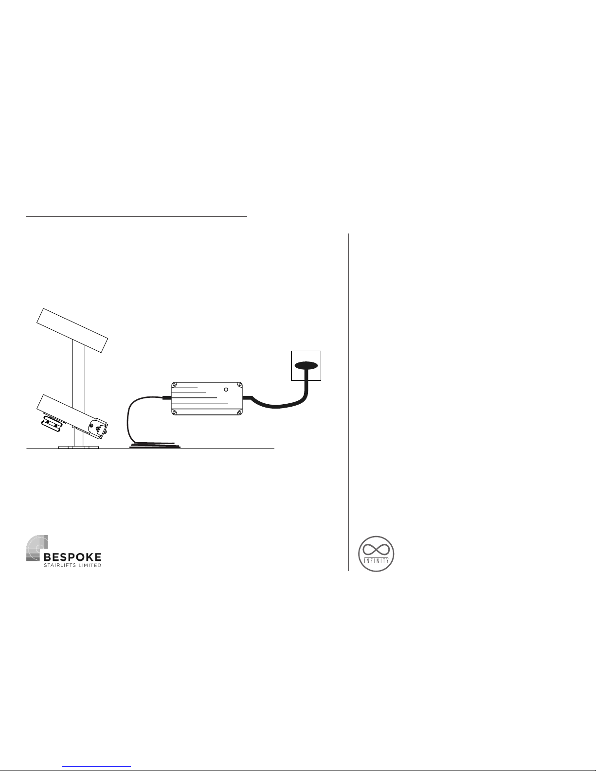
MOUNTING THE CHARGER
Find a suitable power supply as close as
possible to either the top or bottom of the
stairs.
Mount the charger in a suitable position
near the power supply using the screws
supplied. Please ensure the charger is
mounted level and secure.
Leave sufficient length on the power
output to enable easy connection to the
rail charge points.
Do not connect or switch on the power
supply until the rail charge points have
been connected. (See Page 31)
Power Supply
Charging Unit
Power Output
Cable

10
CARRIAGE PREPARATION

11
First unpack all the pre-assembled units
from their packaging, taking care not to
place the carriage on the floor, avoiding
damage. Your carriage will arrive already
pre-assembled as either a manual swivel
option or powered swivel option as per
your order.
CARRIAGE PREPARATION
CARRIAGE & FOOTREST SEAT & ARMREST ASSEMBLY
12
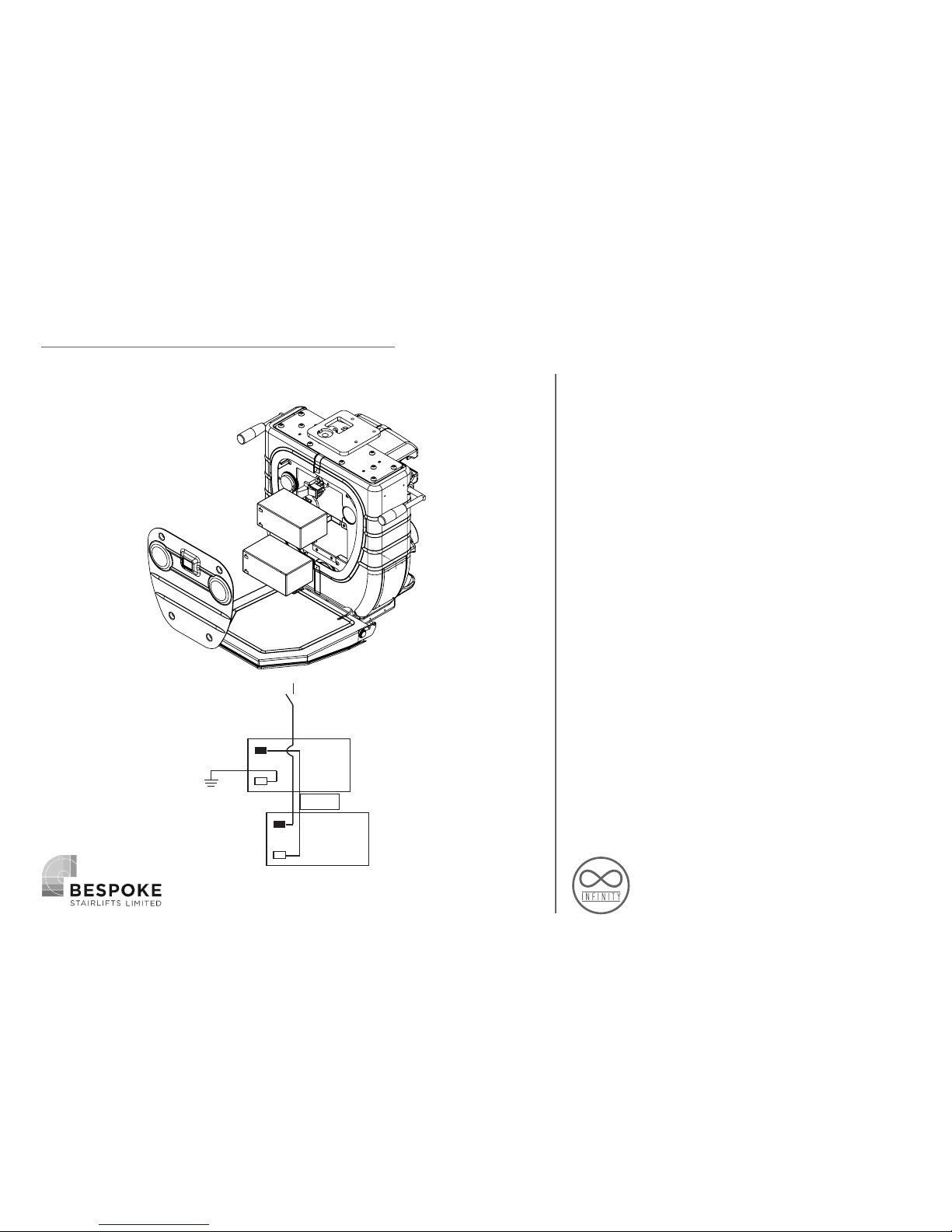
INSTALLING THE BATTERIES
To install the batteries first remove the
front panel by unscrewing the 4 main
screws. Once you’re have inserted the
batteries consult figure 2, making sure the
battery circuit is correct.
CARRIAGE ASSEMBLY
+
-
+
-
FUSE
Fig 1
Fig 2

13
CARRIAGE PREPARATION
LOADING ONTO THE RAIL
Next insert the long loading bar into the
top skate of the carriage and insert the
small cone stopper in the bottom rail tube.
At the top of the stairs lift the carriage
with the loading strap and insert the
loading bar into the top rail tube, slowly
run the carriage along until the small cone
is through the bottom skate. Once the
carriage is securely located on rail it is
safe to let go of the loading strap.
(Loading bar & cone are part of the
separate installation kit.)
Small cone
Loading Bar
Loading strap
Fig 1
Fig 2
14
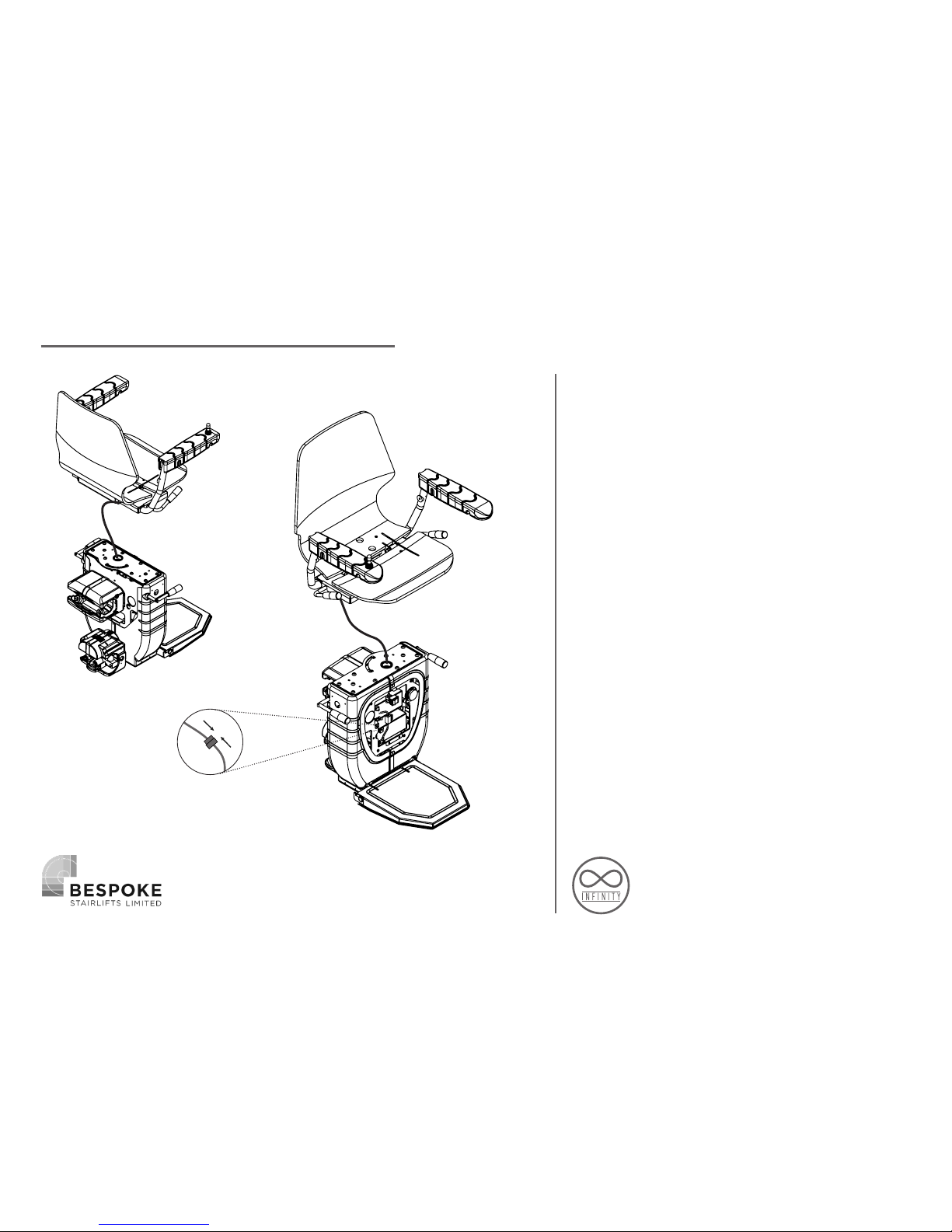
CONNECT THE SEAT BASE WITH ARMS
TO THE CARRIAGE
You can now begin to install the seat to
the carriage. First, lift the seat above
the carriage and feed the joystick cable
down through the hole located in the
seat boss plate, before lowering the seat
down onto the plate ensure to feed all the
cable through when doing so, to prevent
the cable getting trapped under the seat
frame. If the lift is a Manual Swivel, you
must ensure the locator on the swivel lever
is passing through the aperture in the boss
– this is not required on a powered swivel.
CARRIAGE ASSEMBLY

15
Now line the holes up on the seat frame
down to the boss plate below. Fix with the
2 shorter bolts towards the front of the
seat, the 2 longer ones to the back. Please
ensure the correct screws are positioned in
the correct holes as incorrect installation
will result in damage. Then connect the
joystick cable to the PCB cable which is
located inside the chassis above the upper
battery (Fig 1), making sure the 2 cables
are free to move as the chair rotates, then
the front battery cover can now be fixed
back on. Insert the key into the arm and
turn to the in position, the carriage is now
ready to run down the rail.
CARRIAGE ASSEMBLY
Fig 1
2x Long Screws
2x Short Screws

16
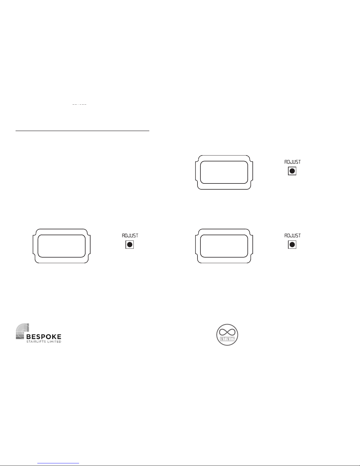
Switch on the lift by pressing the orange
switch on the front of the carriage to the
on position. Remove the PCB cover for
access to the programming buttons and to
have a clearer view of the LCD screen. The
lift should already come set up correctly
ready for programming, but this can be
checked by going through the menu
function on the screen.
The lower ‘SCROLL’ button is used to cycle
through the menu options and the top
‘ADJUST’ button to change an option. For
example, scroll to the Swivel option and
press the adjust button to choose Manual
or powered. It is best to check through all
these beforehand to make sure everything
is set up correctly.
RUNNING THE CHAIR ON
MANUAL

17
The lift will not run unless in program
mode or already programmed to the rail.
To put the lift into Program mode, Press
the scroll button until you see ‘POSITION’
(this is the first option you come to if
scrolling from the home screen), then
press and HOLD the scroll button and this
will change to ‘Program LO 1500’ – you are
now in program mode and able to drive
the lift onto the rail. Run the chair to a
desired position on the rail so you are now
able to start mounting the charging points.
RUNNING THE CHAIR ON
Position
PROGRAM
Lo 1500
HOLD

18
Return to the rail and fit the charge points
to both the top and bottom connecting
the core cable at both ends, use the
diagram in the installation guide to ensure
correct polarity (+ to the lower charging
strip and - to the top) once you are happy
with the positions fasten the final end stop
brackets at the top and bottom of the rail.
When placing the final end stops and
charging points please ensure;
1. The lower skate of the carriage does not
touch the floor before engaging with the
final end stop. This could result in damage
to the skate mechanism. If the distance
is incorrect you may need to adjust the
charging terminal.
2. When the charging terminals are
engaged make sure there is ONLY 5mm-
10mm gap between the end stop and
the skate cover, if for any reason the lift
overruns the charge points it will ensure
the lift is still on charge.
INSTALL RAIL CHARGE POINTS
+
+- -
+ -
+
-
19
PROGRAMMING
HAND
This is to determine the hand of the lift
LEFT / RIGHT
MODE
Used for different lift types as will both Curved
and Straight lifts will use the same PCB &
software. *Straight lift not yet available*
CURVED/STRAIGHT
POSITION
Used for programming the lift to the rail (press
and hold scroll button to get in/out of Program
mode), also shows the encoder count once
programmed.
NO FUNCTION
Below is breakdown and explanation
of each of the menu options shown
on the display when using the scroll
/ adjust button. The home screen will
show lift status, for example, ‘LIFT
READY’ or OFF CHARGE’ before you
scroll through the menu, the display
will automatically go back to the
lift status after 5 seconds of neither
button being pressed.

20
INT.CP
When the lift has an Intermediate Charging Point
(INT. CP) the lift will always park here from the remote
controls, but you have the option for the joystick,
PASS – to always pass the charge point when using the
joystick (when the lift only requires the charge point
STOP – To stop on the charge point when using the
joystick (usually required where the customer has an
intermediate landing they need to be able dismount
the lift).
PASS / STOP
TRAVEL
Option for the lift to BEEP when travelling up or
down the rail
QUIET / ALARM
LANGUAGE
Choose 1 of 7 language options;
English, Spanish,French,
German, Italian, Portuguese & Dutch
SELECT LANGUAGE
SWIVEL
This option is to set up whether the lift has a
manual or powered swivel
MANUAL / POWERED
PROGRAMMING
Other manuals for Infinity
2
Table of contents
Other Bespoke Stairlift manuals


