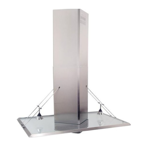
Best KEX3500 User manual

BEST BY BROAN P.O. Box 140, Hartford, WI 53027
Model KEX3500
ENGLISH.......................................3
FRANÇAIS..................................15
ESPAÑOL....................................27


- 3 -
READ AND SAVE THESE INSTRUCTIONS
WARNING
TO REDUCE THE RISK OF FIRE, ELECTRIC SHOCK, OR INJURY TO PERSONS,
OBSERVE THE FOLLOWING:
1. Usethisunitonlyinthemannerintendedbythemanufacturer.Ifyouhavequestions,
contactthemanufacturerattheaddress or telephonenumberlisted in thewarranty.
2. Before servicing or cleaning unit, switch power off at service panel and lock service
panel to prevent power from being switched on accidentally. When the service
disconnectingmeanscannotbelocked,securelyfastenaprominentwarning device,
suchasatag,totheservicepanel.
3. Installation work and electrical wiring must be done by a qualified person(s) in accor-
dancewith all applicable codesandstandards, including fire-ratedconstructioncodes
andstandards.
4. Sufficientairis neededfor propercombustion andexhausting ofgasesthroughtheflue
(chimney)of fuelburningequipment topreventbackdrafting. Followthe heating equip-
mentmanufacturer’sguidelinesand safety standards such as those published by the
National Fire Protection Association (NFPA), and the American Society for Heating,
RefrigerationandAir ConditioningEngineers(ASHRAE), andthelocalcodeauthorities.
5. When cutting or drilling into wall or ceiling, do not damage electrical wiring and other
hiddenutilities.
6. Ductedfansmust always be vented totheoutdoors.
7. Donotuse this unit withanyseparate solid-state speed controldevice.
8. Toreducetheriskof fire, use only metal ductwork.
9. Thisunitmust begrounded.
TOREDUCE THE RISKOF A RANGETOPGREASE FIRE:
A. Never leave surface units unattended at high settings. Boilovers cause smoking and
greasyspillovers that mayignite.Heat oilsslowlyon low ormediumsettings.
B. Alwaysturn hood ON when cooking at high heat or when flambeing food (i.e. Crepes
Suzette,Cherries Jubilee, Peppercorn Beef Flambe’).
C. Cleanventilatingfansfrequently.Greaseshouldnot beallowedtoaccumulateonfanor
filter.
D. Use proper pan size. Always use cookware appropriate for the size of the surface
element.
WARNING
TOREDUCETHE RISK OF INJURY TO PERSONS INTHEEVENTOF A RANGE TOP
GREASEFIRE,OBSERVE THEFOLLOWING:*
1. SMOTHERFLAMESwithaclose-fitting lid,cookie sheet,or metaltray, thenturn offthe
burner.BE CAREFULTOPREVENT BURNS.Ifthe flamesdo not goout immediately,
EVACUATEANDCALLTHEFIREDEPARTMENT.
2. NEVERPICKUP AFLAMINGPAN -You maybeburned.
3. DONOTUSE WATER,including wetdishcloths ortowels-violentsteam explosionwill
result.
4. Useanextinguisher ONLY if:
A. YouknowyouhaveaClassABCextinguisherandyoualreadyknowhow tooperate
it.
B. Thefireissmall and containedinthe area whereitstarted.
C. The firedepartmentisbeingcalled.
D. You can fight the firewithyourback to an exit.
*Based on “KitchenFireSafety Tips”publishedby NFPA.
!
INTENDED FOR DOMESTIC COOKING ONLY
!
- 4 -
!
CAUTION
1. Toreduceriskoffireandtoproperly exhaustair,besuretoductairoutside.Donot vent
exhaustair intospaces withinwallsor ceilingsorinto attics,crawl spaces,orgarages.
2. Takecarewhen using cleaningagentsor detergents.
3. Avoidusingfood productsthatproduce flames underthe Range Hood.
4. Forgeneralventilating use only.Donot usetoexhaust hazardous orexplosivemate-
rialsandvapors.
5. Toavoidmotor bearingdamage andnoisyand/or unbalancedimpellers, keepdrywall
spray,constructiondust, etc. off power unit.
6. Yourhoodmotor hasa thermaloverload whichwillautomaticallyshutoff themotor ifit
becomesoverheated.Themotorwillrestartwhen itcools down.If themotor continues
toshutoff and restart, have the hood serviced.
7. Forbestcaptureofcooking impurities,the bottomof thehood shouldbeaminimumof
24"and a maximum of30"above the cooking surface.
8. Twoinstallersare recommended becauseofthe largesizeand weight ofthishood.
9. Thisproductisequipped with a thermostat which may start blower automatically. To
reduce the risk of injury and to prevent power from being switched on accidentally,
switchpoweroff at service panel and lock or tag service panel.
10. Usewithapprovedcord-connection kit only.
11. Pleasereadspecificationlabel onproduct forfurtherinformation andrequirements.
12. To reduce the risk of fire and electric shock, install this range hood only with Best by
BroanExteriorblowermodelsEB6,EB9,EB12,orEB15, orBestbyBroanIn-LineBlower
modelsILB3,ILB6,ILB9,or ILB11.Other Blowerscannot besubstituted(Blowerssold
separately).

- 5 -
PREPARE THE HOOD
Unpack hood and check contents.
You should receive:
1 - Hood
1 - Decorative Flue Assembly
1 - Discharge Collar
1 - Parts Bag (B080810482) containing:
1 - Mounting Bracket
1 - Flue Mounting Bracket
8 - Mounting Screws (4,8 x 38mm Pan Head)
4 - Mounting Screws (3,9 x 9,5mm Pan Head)
2 - Mounting Screws (2,9 x 9,5mm Pan Head)
8 - Drywall Anchors
1 - Installation Instructions
1 - Warranty Card
MOUNTING
BRACKET
DISCHARGE
COLLAR
FLUE MOUNTING
BRACKET 8 MOUNTING SCREWS
(4,8 x 38mm Pan Head) 8 DRYWALL
ANCHORS
4 MOUNTING
SCREWS (3,9 x 9,5mm
Pan Head)
DECORATIVE
FLUE
2 MOUNTING
SCREWS (2,9 x 9,5mm
Pan Head)

- 6 -
HOOD
24” TO 30” ABOVE
COOKING SURFACE
DECORATIVE
FLUE
8” ROUND
DUCT
EXTERIOR OR IN-LINE BLOWER SELECTION
CAUTION: Either an exterior blower or in-line blower may be used with this hood.
The KEX3500 hood must be installed with blower models EB6, EB9, EB12, EB15,
ILB3, ILB6, ILB9, or ILB11 only. Other Blowers cannot be substituted (Blowers sold
separately).
TheblowermustbeULlistedforCanadianandU.S.use,andevaluatedforusewith
solid state speed control, rated 120V, 60 Hz, 6.0 A max.
INSTALL THE DUCTWORK
NOTE: To reduce the risk of fire, use only metal ductwork.
1. Choose the location where the Exterior or In-Line Blower will be mounted. See
illustrations below for mounting location suggestions and restrictions.
2. A straight, short duct run will allow the hood to perform most efficiently.
3. Long duct runs, elbows and transitions will reduce the performance of the
hood. Use as few of them as possible. Larger ducting may be required for best
performance with long duct runs.
4. After the Exterior or In-Line Blower has been installed, connect round metal
ductwork and work back towards the hood location. Use duct tape to seal joints
between ductwork sections.
5. An 8” round to 10” round transition (Model 414) is required. For best air
performance, install the transition as close to the range hood as possible.
OK
OK
SUGGESTED MOUNTING LOCATIONS
EXTERIOR BLOWER
CAUTION: MAY NOT FIT
UNDER EAVES OF SINGLE
STORY HOMES
EXTERIOR
BLOWER
10” ROUND
DUCT
EXTERIOR
BLOWER
8” TO 10”
ROUND
TRANSITION
8” ROUND
ELBOW
10”
ROUND
DUCT

- 7 -
IN-LINE BLOWER
FRAMING BEHIND DRYWALL
43-5/16” to 49-5/16”
above cooktop
INSTALL MOUNTING
BRACKET
1. Construct wood wall framing that is flush
with interior surface of wall studs.
Make sure:
a) theframing iscentered overinstallation
location.
b) the height of the framing will allow the
mounting bracket tobe secured to the
framing within the dimensions shown.
2. Afterwallsurfaceisfinished, securemount-
ing bracket to framing using dimensions
shown.
43-5/16"= bottom of hood 24" above
cooktop
49-5/16"= bottom of hood 30" above
cooktop

- 8 -
INSTALL DUCT COLLAR
1. Fold the 2 tongues outwards.
2. Fix the discharge collar onto the hood; it
must be fixed either by means of 2
mounting screws (3,9x9,5mm).
DISCHARGE
COLLAR
TONGUES
MOUNTING
SCREWS
(4,8x38mm)
RECTANGULAR
CUTOUT
MOUNTING SCREWS
(4,8x38mm) WALL FRAMING
MOUNTING
BRACKET
INSTALL THE
HOOD
1. Hang the hood from the
bracket through the
rectangular cut-out on
thebackofthehood.Cut-
out is larger than the
bracket to allow for
horizontal adjustment.
The bottom of the hood
should be 24" to 30"
above the cooking
surface.
2. Secure the hood with
mounting screws (4,8x38mm). Use drywall anchors, provided, if wall studs or
framing are not available.

- 9 -
WIRING
CAUTION: All electrical wiring should
be done by a qualified person (s) in
accordance with all applicable codes and
standards. This range hood must be
properly grounded.
Do not turn power on at service panel until
all wires have been connected.
Blowerconnectionathood:
1. Run 2-wire plus ground power cable from
theExteriororIn-LineBlowertothehood’s
wiring box marked “motor connection”.
2. Removethe cover from the wiring box and
remove one knockout.
3. Feed 6” of cable through the knockout
openingand secure the cable to the wiring
box with an appropriate connector.
4. Make electrical connections at the hood.
Connect white-to-white, red-to-black and
green-to-ground.
5. Replace the wiring box cover and screws.
make sure wires are not pinched between
the cover and box.
Exterior or In-line blower connection:
1. Makeelectrical connections atthe exterior
orin-line blower(seeinstructionsprovided
with the exterior or in-line blower).
Powerconnection at hood:
1. Run120 VAC electrical power cable to the
hood wiring box marked “120VAC input”.
2. Removethe cover from the wiring box and
remove one knockout.
3. Feed 6” of cable through the knockout
openingand secure the cable to the wiring
box with an appropriate connector.
4. Make electrical connections at the hood.
Connect white-to-white, black-to-black
and green-to-ground.
5. Replace the wiring box cover and screws.
Make sure wires are not pinched between
the cover and box.
BOX MARKED
“120 VAC INPUT”
BLOWER CONNECTION AT HOOD
BOX MARKED
“MOTOR
CONNECTION”
Exterior or In-Line
blower
!
CONNECT:
WHITE-TO-WHITE,
RED-TO-BLACK,
GREEN-TO-GROUND.
POWER CONNECTION AT HOOD
CONNECT:
WHITE-TO-WHITE,
BLACK-TO-BLACK,
GREEN-TO-GROUND.
120 Volt 60Hz
LINE-IN

- 10 -
FLUE MOUNTING
BRACKET MOUNTING SCREWS MOUNTING
SCREWS
(4,8x38mm)
=
=
CONNECT DUCTWORK
Adjustthewidth of theflue mounting bracket
to equal the inside width of decorative flue.
Insert and tighten mounting screws to hold
bracket width.
Use mounting screws (4,8x38mm) and wall
anchors to secure flue mounting bracket to
the ceiling as shown.
1. Use 8" round metal duct to connect the
duct collar on the hood to the ductwork
above.
2. Use duct tape to make all joints secure
and air tight.
3. Carefullyplacethelowerdecorativeflueinto
the recessed area of the range hood top.
4. Extend the upper flue to the ceiling and
secure with two mounting screws
(3,9x9,5mm).
8" ROUND
METAL DUCT
DUCT TAPE
DECORATIVE
FLUE
FASTEN FLUE TO
UPPER BRACKET
WITH MOUNTING
SCREWS

- 11 -
MAINTENANCE
Proper maintenance of the Range Hood will
assure proper performance of the unit.
Grease Filter
The grease filter should be cleaned after
every 30 hours of operation. This range hood
has an operation timer which will alert you
after every 30 hours of use by lighting a red
LED above the “blower speed 0-1 button”.
Use a warm detergent solution. Grease filter
is dishwasher safe.
To remove the grease filter, press inward on
the clamp at the handle and pull the filter
downward.
Hood Cleaning
Stainless steel is one of the easiest materials to keep clean. Occasional care will
help preserve its fine appearance.
Cleaning tips:
OHot water with soap or detergent is all that is usually needed.
OFollow all cleaning by rinsing with clear water. Wipe dry with a clean, soft cloth
to avoid water marks.
OFor discolorations or deposits that persist, use a non-scratching household
cleanser or stainless steel polishing powder with a little water and a soft cloth.
OFor stubborn cases, use a plastic scouring pad or soft bristle brush together
with cleaser and water. Rub lightly in direction of polishing lines or "grain" of the
stainless finish. Avoid using too much pressure which may mar the surface.
ODO NOT allow deposits to remain for long periods of time.
ODO NOT use ordinary steel wool or steel brushes. Small bits of steel may
adhere to the surface causing rust.
ODO NOT allow salt solutions, disinfectants, bleaches, or cleaning compounds
to remain in contact with stainless steel for extended periods. Many of these
compounds contain chemicals which may be harmful. Rinse with water after
exposure and wipe dry with a clean cloth.
Painted surfaces should be cleaned with warm water and mild detergent only.
GREASEFILTER

- 12 -
LED
BLOWER
SPEED 4
BLOWER
SPEED 2
BLOWER
SPEED 3
BLOWER
ON-OFF /
SPEED 1
LIGHT
SWITCH
OPERATION
Controls
The hood is operated using the (5) push-but-
tons located on the right side of the hood.
The light switch turns the halogen lights on
and off. Push the light switch once to turn the
lights ON - push a second time to turn the
lights ON to a brighter level - push a third time
to turn the lights OFF.
The blower on-off / speed 1 switch turns the
blower on to its lowest running speed. To turn
OFF the blower, push in and hold this blower
switch for approximately 2 seconds.
The blower speed 2 switch turns the blower on to medium-low running speed.
Pressing this switch a second time sets a timer which keeps the blower operating
at this speed for 10 minutes. The LED will blink during this time and the blower will
shut off automatically.
The blower speed 3 and blower speed 4 switches operate the same as blower
speed 2 switch except: Blower speed 3 is medium-high and blower speed 4 is
high.
After every 30 hours of operation, the LED above the “blower speed 1 switch” will
be illuminated (RED) and blink for 30 seconds after turning off the blower. This is
a reminder to clean the grease filter. Once the grease filter is cleaned and installed,
press in and hold the “light switch” button for approximately 2 seconds during the
blink of the LED.
HEAT SENTRY™
Your hood is equipped with a HEAT SENTRY™ thermostat. This thermostat is a
device that will turn on or speed up the blower if it senses excessive heat above
the cooking surface.
1) If blower is OFF - it turns blower ON to HIGH speed.
2) If blower is ON at a lower speed setting - it turns blower up to HIGH speed.
When the temperature level drops to normal, the blower will return to its original
setting.
WARNING
The HEAT SENTRY thermostat can start the blower even if the hood is turned
OFF. When this occurs, it is impossible to turn the blower OFF with its switch.
If you must stop the blower, do it from the main electrical panel.

- 13 -
FUSE REPLACEMENT
SWITCH OFF THE ELECTRICITY SUPPLY.
Remove the decorative flue.
Remove the electrical box support.
Open the electrical box working from the
inside of the hood.
Replacewith the same type of fuse (5x20mm,
4A, 125V).
FUSE DECORATIVE
FLUE
ELECTRICAL
BOX
ELECTRICAL
BOX
SUPPORT
HALOGEN BULBS
This range hood requires two halogen bulbs
(Type JC, 12Volt, 20Watt Max, G-4 Base).
ALWAYS SWITCH OFF THE ELECTRICITY
SUPPLY BEFORE CARRYING OUT ANY
OPERATIONSONTHEAPPLIANCE.
To change bulbs:
1. Loosen the ring nut by turning it
counterclockwise.
2. Remove the bulb by pulling sideward - DO
NOTROTATE. CAUTION: BULB MAY BE
HOT!
3. Replace with Type JC, 12Volt, 20Watt Max, G-4 Base halogen bulb. Do not
touch replacement bulb with bare hands!
RING NUT

- 14 -
WARRANTY
BROAN ONE YEAR LIMITED WARRANTY
Broanwarrantsto the originalconsumerpurchaser of itsproductsthat such productswillbe free fromdefectsin materials
or workmanship for a period of one year from the date of original purchase. THERE ARE NO OTHER WARRANTIES,
EXPRESS OR IMPLIED, INCLUDING, BUT NOT LIMITED TO, IMPLIED WARRANTIES OR MERCHANT ABILITY OR
FITNESS FOR A PARTICULAR PURPOSE.
Duringthisone-year period,Broanwill, at itsoption, repair orreplace,without charge,anyproduct orpartwhich is foundto
bedefectiveunder normal useand service.
THIS WARRANTY DOES NOT EXTEND TO FLUORESCENT LAMP STARTERS, TUBES, HALOGEN AND
INCANDESCENDTBULBS. Thiswarranty doesnot cover(a)normal maintenanceandservice or(b) anyproductsor parts
which have been subject to misuse, negligence, accident, improper maintenance or repair (other than by Broan), faulty
installationorinstallation contrary torecommendedinstallation instructions.
Thedurationof anyimplied warrantyislimited tothe one-yearperiodas specifiedfor theexpresswarranty. Some statesdo
not allow limitation on how long an implied warranty lasts, so the above limitation may not apply to you.
BROAN’SOBLIGATIONTOREPAIROR REPLACE,AT BROAN’SOPTION, SHALLBETHE PURCHASER’SSOLE AND
EXCLUSIVEREMEDYUNDER THISWARRANTY. BROAN SHALLNOTBE LIABLEFOR INCIDENTAL,CONSEQUEN-
TIAL OR SPECIAL DAMAGES ARISING OUT OF OR IN CONNECTION WITH PRODUCT USE OR PERFORMANCE.
Some states do not allow the exclusion or limitation of incidental or consequential damages, so the above limitation or
exclusionmaynot apply toyou.
Thiswarranty givesyou specificlegal rights,and youmay alsohave otherrights, whichvary fromstate tostate. This warranty
supersedes all prior warranties.
Toqualifyforwarrantyservice, youmust (a)notify Broanattheaddressstated belowor telephone:1-800-637-1453, (b)give
themodelnumberandpartidentification and(c)describe thenatureofanydefectintheproductorpart. At thetimeof requesting
warrantyservice,you must presentevidenceof the originalpurchase date.
BEST BY BROAN, P.O. Box 140 Hartford, Wisconsin 53027

- 15 -
LISEZ ET CONSERVEZ CES INSTRUCTIONS
AVERTISSEMENTS
POUR REDUIRE LES RISQUES D’INCENDIE, DE DECHARGES ELECTRIQUES OU
DE DOMMAGES AUX PERSONNES, OBSERVEZ LES INSTRUCTIONS SUIVANTES:
1. N’utilisezcetappareilquecommecelaestindiquéparleconstructeur.Sivousavezdes
problèmes,contactezlefabriquantàl’adresseouaunumérodetéléphoneindiquésdans
lagarantie.
2. Avantdepourvoiràl’entretienouaunettoyagedevotreappareil,éteignez-leautableau
descommandesoubloquezletableaudescommandesafind’éviterdelemettreenmarche
accidentellement.Sivousnepouvezpasbloquerlesystèmepermettantd’éteindrevotre
appareil,appliquezunavertissementextérieurd’unefaçonsure,commeparexempleun
panneau,surletableaudescommandes.
3. L’assemblageetlaconnexionélectriquedoiventêtrefaitspardespersonnesqualifiées
enrespectantlesnormesetrèglementsenvigueur,ycomprislesnormesetrèglements
concernantlespossibilitésd’incendie.
4. Ilestindispensablequ’ilyaitsuffisammentd’airpourquelacombustionetl’évacuationdes
gazàtraversletuyaudubrûleurducombustibleaitlieusansretourdeflamme.Suivez
lesindicationsdonnéesparlefabricantdubrûleurainsiquelesnormesdesécuritécomme
cellesquisontpubliéesparl’AssociationNationalepourlaProtectioncontrelesIncendies
NationalFireProtectionAssociation(NFPA)etlaAmericanSocietyforHeating,Refrigeration
andAirConditioningEngineers(ASHRAE),etlesautoritéslocalesenmatièredenormes.
5. Quandvouscoupezoupercezdestrousdanslemurouleplafond,n’abîmezpaslesfils
électriquesouautres.
6. Leventilateurcanalisédoittoujoursévacuerl’airversl’extérieur.
7. N’utilisezpascetappareilavecunappareilcontrôlantlavitesseàétatsolide.
8. Afindediminuertoutrisqued’incendien’utilisezquedesconduitsenmétal.
9. Votreappareildoitêtrereliéàlaterre.
ATTENTION-POURREDUIRELESRISQUESD’INCENDIEDESMATIERESGRASSES
QUISONT EN TRAINDECUIRE:
A. Ne laissez jamais ni vos éléments chauffants, ni vos casseroles ou poêles sur le feu
sans les contrôler si vous réglez l’apport de chaleur sur une position élevée. Si vos
casserolesoupoêles débordent cela provoque de la vapeur etdeséclaboussuresde
graissequi peuvent prendrefeu. Chauffez leshuileslentement àfeubas ou moyen.
B. Faites toujours fonctionnervotre hotte quandvouscuisez à destempératuresélevées
ou quand vous cuisinez des plats flambés. (par ex. crêpes Suzette, Cerises “Jubilé”,
Steackau poivreflambé).
C. Nettoyez régulièrement lesailesdevos ventilateurs. Ne permettezpasque la graisse
s’accumulesur le ventilateurousur le filtre.
D. Utilisez descasserolesde tailleappropriée. Utiliseztoujoursdes ustensilesdecuisson
dontla taille estappropriéeà la surfacedevotre élément decuisson.
AVERTISSEMENTS
POURREDUIRELESRISQUESDEDOMMAGESAUXPERSONNESAUCASOÙVOTRE
CUISINIEREPRENDRAITFEU,OBSERVEZLESINSTRUCTIONSSUIVANTES:*
1. ETEINDRE LES FLAMMES à l’aide d’un couvercle le plus hermétique possible, une
plaqueàgâteaux, ou un plateau enmétal,puiséteindre le brûleur. ATTENTION à NE
PASVOUS BRÛLER.Si lesflammesnes’éteignentpas immédiatement,SORTEZ ET
APPELEZLESPOMPIERS.
2. NEPRENEZJAMAISEN MAINUNEPOÊLEOUUNE CASSEROLEQUIAPRISFEU
-Vouspourriezvous brûler.
3. N’UTILISEZPASD’EAU,ni torchonsouserviettesmouillés - vous provoqueriez une
violenteexplosion devapeur.
SEULEMENT POUR UTILISATION DOMESTIQUE
!!

- 16 -
4. UtilisezunextincteurSEULEMENTsi:
A. Voussavezque vousavez unextincteur ClasseABC, etvousenconnaissezdéjàle
moded’emploi.
B. Ce n’est pasun très grosincendieet qu’il selimiteà l’endroi oùila explosé.
C. Vous êtes entraind’avertir les pompiers.
D. Vous avez la possibilitéd’essayerd’éteindre l’incendie en ayant le dostournévers
uneissue.
* D’après les “Suggestions concernant la Sécurité contre les incendies des cuisines”
publiéesparNFPA.
ATTENTION
1. Pourréduiretoutrisque d’incendieet pourévacuercorrectementl’air,assurez-vous de
prévoirun conduit de ventilationextérieur.Ne videz pas l’air danslesespaces limités
pardesmurs ou des plafonds, les combles, lespassagesétroitsou les garages.
2. Faitestrèsattention quandvous utilisez desproduits denettoyageou desdétergents.
3. Évitezd’utiliserdes alimentspouvant s’enflammersous laRangeHood.
4. N’utilisezcetappareilquepouruneventilationgénérale.Ne l’utilisezpas pourévacuer
desmatières ou des vapeursdangereusesou qui peuvent exploser.
5. Pouréviterde causerdes dommagesaumoteur etde rendrelesrotors bruyantset/ou
non équilibrés, évitez que les sprays pour murs secs, la poussière de construction
entrenten contact aveclapartie électrique.
6. Lemoteurdevotrehotteaunthermostatquiéteindraautomatiquementlemoteurs’ilest
surchauffé. Le moteur se remettra en marche lorsqu’il se sera refroidi. Si le moteur
continueà s’éteindre et àseremettre en marche,faitesvérifier votre hotte.
7. Pourmieuxcapturer les impuretés de cuisine,lebas de votre hottedevraitêtreà une
distance minimum de 24” et à une distance maximum de 30” au-dessus du plan de
cuisson.
8. Vuquecettehotte est grande et lourde, ilestrecommandéde confier l’installation de
cettehotte à deux personnes.
9. Ce produit est doté d’un thermostat qui active automatiquement le moteur. Pour
réduirelerisquededommagesetéviterl’activationaccidentelle,positionnerl’interrupteur
dupanneau deservice surlaposition OFFetbloquer lepanneau deserviceou mettre
unavertissementexterne,parexemple une plaquette.
10. Utiliseruniquementavecun kit deconnexionpour alimentation homologué.
11. Nous vous recommandons de lire l’étiquette indiquant les caractéristiques de votre
hottepour deplusamples informations et exigences.
12. Pour diminuer les dangers d’incendie ou de choc électrique, installer cette hotte de
cuisineuniquementparmilesmodèlesdeventilateursexterne“BestdeBroan”modèles
EB6, EB9, EB12, ou EB15, ou ventilateurs “In-Line, Best de Broan” Modèles ILB3,
ILB6,ILB9,ou ILB11. On ne peut pas utiliser d’autres ventilateurs (Les ventilateurs
sont vendus séparément).
!

- 17 -
PREPAREZ LA HOTTE
Enlever la hotte dans l’emballage et controller le
contenu.
Vous devez recevoir :
1 - Hotte
1 - Conduit décoratif
1- Collier d’évacuation
1 - Sachet (B080810482) avec:
1 - Étrier d’assemblage
1 - Étrier de support
8 - Vis d’assemblage (4,8 x 38mm Tête ronde)
4 - Vis d’assemblage (3,9 x 9,5mm Tête ronde)
2 - Vis d’assemblage (2,9 x 9,5mm Tête ronde)
8 - Chevilles
1 - Instructions pour l’installation
1 - Garantie
ETRIER
D’ASSEMBLAGE
COLLIER
D’EVACUATION
ETRIER DE SUPPORT 8 VIS D’ASSEMBLAGE
(4,8 x 38mm Tête ronde) 8 CHEVILLES
4 VIS D’ASSEMBLAGE
(3,9 x 9,5mm Tête
ronde)
CONDUIT
DECORATIVE
2 VIS D’ASSEMBLAGE
(2,9 x 9,5mm Tête
ronde)

- 18 -
DE 24”(61cm) À 30”
(76cm) AU-DESSUS
DU PLAN DE CUISSON
TUYAU ROND
DE 10”
HOTTE
CONDUIT
DÉCORATIF
TUYAU
ROND DE 8”
CHOIX DE VENTILATEUR EXTERNE OU “IN-LINE”
ATTENTION: avec cette hotte, on peut utiliser soit un ventilateur externe soit
“In-Line”. La hotte KEX3500 doit être installée avec un ventilateur des
modèles suivants EB6, EB9, EB12, EB15, ILB3, ILB6, ILB9, ou ILB11
uniquement. On ne peut pas utiliser d’autres ventilateurs (les ventilateurs
sont vendus séparément).
Le ventilateur doit être compris dans la liste UL pour l’utilisation au Canada et
aux USA et approuvée pour l’utilisation avec un “dispositif de contrôle de la
vitesse” à l’état solide, dont les données sur la plaque sont 120V, 60 Hz, 6.0 A
max.
INSTALLATION DU SYSTEME D’EVACUATION
NOTE:Pourréduirelesrisquesd’incendien’utiliserquedesconduitsmétalliques.
1. Choisir l’emplacement où le ventilateur externe ou le ventilateur “In-Line” sera
monté. Voir les illustrations ci-dessous pour le choix de l’emplacement et les
éventuelles restrictions à suivre.
2. Un conduit d’évacuation étroit et court rendra la hotte plus performante.
3. Des conduits d’évacuation longs, avec des coudes et des raccords rendront la
hotte moins efficace. Les utiliser le moins possible. En cas de conduits
d’évacuation longs on utilisera un diamètre supérieur.
4. Après avoir installé le ventilateur externe ou le ventilateur “In-Line”, raccorder le
tuyau métallique rond dans le sens de l’emplacement de la hotte. Utiliser du
chaterton pour fermer hermétiquement les joints entre les tuyaux.
5. Dans le modèle 414, il faut un tuyau d’un diamètre de 8” à 10” .Pour obtenir de
bons résultats il faut installer la transition le plus près possible de la hotte
OK
OK
SUGGESTIONS POUR LE MONTAGE
VENTILATEUR EXTERNE
ATTENTION: NE PAS INSTALLER
SOUS L’AVANT-TOIT D’UNE
MAISON A UN ETAGE
VENTILATEUR
EXTERNE
VENTILATEUR
EXTERNE
TRANSITION
DE 8” à 10”
(de 20cm à
25cm)
COUDE
ROND
DE
8”
TUYAU
ROND
DE 10”

- 19 -
CADRE POUR LE MUR
de 43-5/16”(110cm) à 49-5/
16”(125,2cm) au-dessus du plan de
cuisson
43-5/16"(110cm) = si la distance entre la hotte
et le plan de cuisson c’est de 24”(61cm).
49-5/16"(125,2cm) = si la distance entre la
hotte et le plan de cuisson c’est de 30” (76cm).
INSTALLATION ETRIER
D’ASSEMBLAGE
1. Construisez un cadre en bois pour le mur
dont les vis-pivot ne dépassent pas.
Assurez-vous:
a) que le cadre est centré au-dessus de
l’emplacement de l’installation.
b) la hauteur du cadre permettra que
l’étrier d’assemblage soit fixé au cadre
en respectant les dimensions indiquées.
2. Aprèsavoirterminé la surfacedu mur, fixez
l’étrier d’assemblage au cadre en
respectant les dimensions qui sont
indiquées.
VENTILATEUR IN-LINE

- 20 -
INSTALLATION DE
VOTRE HOTTE
1.Accrochez votre hotte à
l’étrier par le trou
rectangulaire qui se
trouve derrière votre
hotte. Le trou est plus
grand que l’étrier afin de
vous permettre d’ajuster
le tout horizontalement.
Le fond de votre hotte
devrait être à entre 24”
(61cm)et30”(76cm)au-
dessus de la surface de
cuisson.
2.Fixez votre hotte avec des vis d’assemblage (4,8x38mm). Utilisez des chevilles
pour mur à sec, qui vous sont fournies, si vous ne trouvez pas les vis-pivot ou le
cadre.
TROU
RECTANGULAIRE
ETRIER
D’ASSEMBLAGE
VIS
D’ASSEMBLAGE
(4,8x38mm)
PLANCHEDEBOISPOURL'ADAPTATION
VIS D’ASSEMBLAGE
(4,8x38mm)
INSTALLATION DU COLLIER
D’EVACUATION
1. Pliez les 2 languettes vers l’extérieur.
2. Fixez le collier d’évacuation sur la hotte
au moyen de 2 vis d’assemblage
(3,9x9,5mm).
COLLIER
D’EVACUATION
LANGUETTES
Table of contents
Languages:
Other Best Ventilation Hood manuals

Best
Best IBF4I36SB User manual

Best
Best WPP1 Series User manual

Best
Best IP29M Series User manual

Best
Best U10242E User manual

Best
Best CC34IQSB User manual

Best
Best KEX30 User manual

Best
Best LIFT FPX User manual

Best
Best WP29M SERIES User manual

Best
Best CC34E63SB User manual

Best
Best UCB3I Series User manual