manuals.online logo
Brands
  1. Home
  2. •
  3. Brands
  4. •
  5. Big Daishowa
  6. •
  7. Industrial Equipment
  8. •
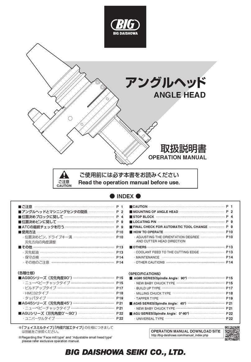
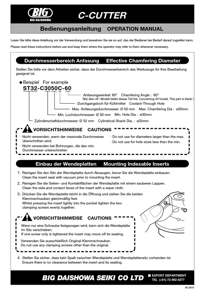
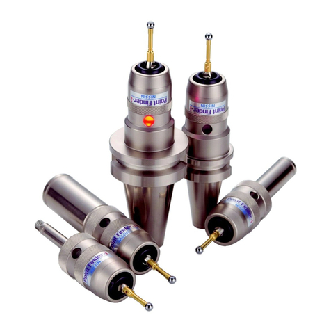
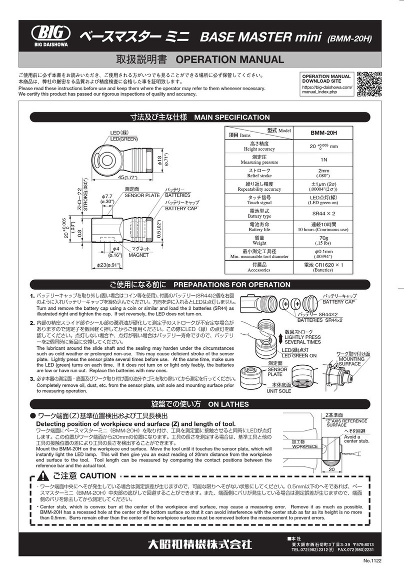
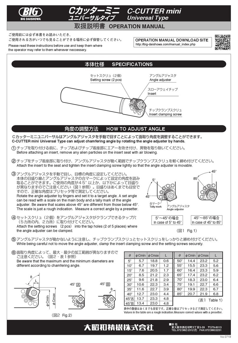
  9. Big Daishowa BBT50-AG90-FMA25.4S-190S User manual

Big Daishowa BBT50-AG90-FMA25.4S-190S User manual

취급 설명서
사용전에 반드시 본 설명서를 읽어 주십시오.
앵글 헤드
페이스 밀 타입
앵글 헤드의 전반적인 취급 설명에 대해서는 「앵글 헤드 취급 설명서」를 참조
하십시오.
ANGLE HEAD
FACE MILL TYPE
OPERATION MANUAL
Please be sure to read this manual before using the product.
Consult the separate operation manual for Angle Head also regarding the
general handling of the Angle Heads.
■사양
■인선 방향 각도 조정
 ・절삭 공구 장착
 ・위치 결정 핀과 인선 방향의 각도 조정
 ・위치 결정 핀과 인선 방향의 각도 조정(90분할)°
 ・위치 결정 핀과 인선 방향의 각도 조정
(노크 핀으로 고정)
앵글헤드를구입해주셔서대단히감사합니다.사용전에반드시본설명서를읽어보시고
사용하시는분전원이언제나확인가능한장소에보관하여주시기를부탁드립니다.
주 의
제품을올바르게사용하지않았을경우,
사용자가상해를입을우려가예상될때및물적손해가예상되는것.
안전에관한표시에대해 Regarding the safety
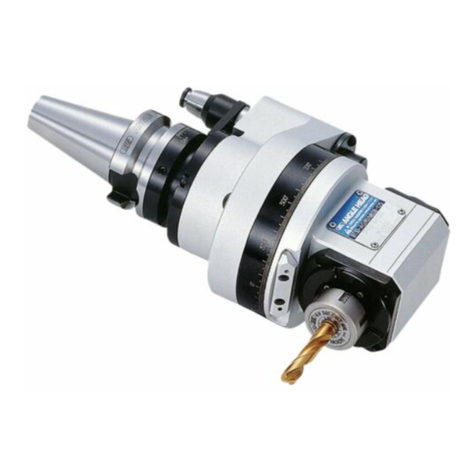
앵글헤드는기계의가공방향을바꾸어주는홀더로셋업시간및공정단축으로작업의효율성을
높일수있습니다.또한ATC교환을통한자동운전이가능합니다.
○앵글헤드에대하여
CAUTION
INDEX
본설명서에서는제품을안전하게사용하기위해서다음과같은표시를하고있습니다.
내용을잘읽어보시고바르게사용하십시오.
P1
P2
P2
P2
P3
P4
■SPECIFICATIONS
■
ADJUSTING THE CUTTER HEAD THROUGH 360°
 ・MOUNT OF THE CUTTING TOOL
 ・
ADJUSTING THE CUTTER HEAD THROUGH 360°
 ・
ADJUSTING THE CUTTER HEAD THROUGH 360°
(EVERY 90 DEGREES)
 ・
ADJUSTING THE CUTTER HEAD THROUGH 360°
(Fixing by knock pin)
P1
P2
P2
P2
P3
P4
Thank you for purchasing the ANGLE HEAD. Please read these instructions before
use and keep them where the operator may refer to them whenever necessary.
INDEX
ANGLE HEAD
The following indicator is used in the operation manual to signify points relating to safe operation.
Please ensure these points are fully understood and followed correctly.
The Angle Head contributes to efficient machining by reducing setup times and production
processes, allowing automatic tool change and full adjustment of the cutter head direction.
Should this equipment be incorrectly operated injury is possible to the
operator, or other personnel in the area. Equipment may also be damaged.
1
사 양 SPECIFICATION
BBT50-AG90-FMA25.4S-190S
BDV50-AG90-FMA25.4S-190S
HSK-A100-AG90-FMA25.4S-200S
회전 비율
REDUCTION RATIO
최고 회전수
MAX. RPM
형 번
MODEL
1 : 1 1,500min-1
질 량
WEIGHT
19.2kg
18.4kg
CAUTION주 의
・최고회전수이상으로는절대사용하지마십시오.
・최고회전수는유닛의구조에의한안전면에서의한계값이며,최고회전수에서의가공을
보장하는것은아닙니다.
・가공시에는낮은절삭조건에서시작하여앵글헤드에적합한조건(떨림발생이없는)에서
사용하여주십시오.
BBT , BDV50 / HSK-A100
・최고회전수부근에서장시간사용하지마십시오.
・A치수는머시닝센터기종에따라부동합니다.
・각도θ는임의각도로조정할수있습니다.
・기계스핀들에대한절삭공구의회전방향은역회전입니다.
38.5 38.5
위치 결정 핀
φ25.4
110
76.5 67
22
φ
140
φ
125
FMA25.4
38.5
32.5
93.5
52.5 41
64
190(HSK:200)
228.5(HSK:238.5)
설정장 A
핀 작동량3
컬러 작동량 6
FIXED LENGTH A
서포트 핀
SUPPORT PIN
위치 결정 암
LOCATING ARM
LOCATING PIN
ORIENTATION DEGREE
위치 결정 컬러
LOCATING COLLAR
PIN COMPRESSION:3
COLLAR COMPRESSION:6
위치 결정 블럭과
드라이브 키 사이 각도θ
BUSH
인선 방향 고정용 부쉬
φ6노크 핀으로 고정
기준면
CUTTING HEAD
REFERENCE FACE
회전수 및 파워
Speed&Power
공칭 파워(Kw)
Nominalpower
)m・fgk(허용 토크
Max.torque
회전수(min)
-1
Spindlespeed
회전수(min
-1
)
Spindlespeed
25
20
15
10
5
0
0 300 600 900 1200 1500 0  300 600 900 1200 1500
18
16
14
12
10
8
6
4
2
0
회전수 및 토크
Speed&Torque
최대 허용 토크는 최고 회전시 구동계의 계산 값
이며 실제로 절삭 가능한 토크와는 다릅니다.
・
・
・Never exceed the maximum spindle speed.
・
The maximum spindle speed is the limit value for safety from the structure. It dose not guarantee cutting operation.
・
For actual cutting operation, begin with lower cutting condition and apply the condition that is suitable to ANGLE HEAD.
The maximum torque is the calculated value of the driving
system at the maximum spindle speed. It is different from
the torque that can be actually applied for cutting
operation.
・ Do not use the unit continuously at around the max RPM.
・ Fixed length “A” varies by the specification of
machining center.
・ Orientation degree can be adjusted arbitrarily.
・ The rotation of the cutting tool is in reverse direction of
the machine spindle.
2
인선 방향의 각도 조정ADJUSTING THE CUTTER HEAD THROUGH 360°
CAUTION주 의
스패너를파이프등으로연장하여사용하지말아주십시오.
커터 장착시 고정 볼트에만 렌치를 걸고 체결하게
되면기어등 손상을 입을 수가 있으므로 반드시
2개의 렌치를 사용하여 체결하여 주십시오.
절삭 공구 장착MOUNT OF THE CUTTING TOOL
위치 결정 핀과인선 방향의 각도 조정
ADJUSTING THE CUTTER HEAD THROUGH 360°
앵글 헤드에 커터를 장착하기 전에앵글 헤드 아버부 및 커터 장착면에 부착한 유분등 이물질을제거
하여 주십시오.
커터 장착시 부속된 훅 스패너를 앵글 헤드 스핀들 단면에 위치한 홈에 걸치고 스핀들을 고정한 상태
에서 커터 고정 볼트를 부속된 L렌치로 체결하여 주십시오.
커터 고정 볼트가 확실하게 체결 되었는지 확인 합니다.
①
②
③
・
・
CAUTION주 의
인선 방향 조정 전에 고정 볼트가 확실히 고정 되었는지를 확인하십시오.인선 방향 조정에는 고정
볼트를 사용하지 않습니다.
다시한번 기준면을 사용하여 인선 방향을 확인 하십시오.
(SIDE LOCK Bolt does not use it for angle adjustment.)
・
・
・인선 방향 조정 볼트를 풀면 인선 방향을 360도 임의의
각도로 조정할 수 있습니다. 헤드 측면에 있는 기준면을
사용하여 수평을 맞추면 조정을 빠르게 할 수 있습니다.
ADJUSTING BOLT
ADJUSTING LOD
SIDE LOCK BOLT
①
②
③
기계에 앵글 헤드를 장착한 상태에서인선 방향 조정
볼트를 조금만 풀어 주십시오.
각도 조정 바를 헤드 측면의 홀에 삽입하고 설정하려는
각도로 헤드를 돌립니다.
기준면을 사용하여 인선 방향을 미세 조정합니다.
인선 방향 조정이 완료하면 부속된 렌치를 사용하여
인선 방향 조정 볼트를 고정합니다. 이때 대각선 방향의
볼트를 교차해가면서 점진적으로 균등하게 체결하여 주십시오.
인선 방향 조정 볼트
고정 볼트
각도 조정바
REFERENCE FACE
기준면
①Remove any flaw, traces of oil and particles from both the inside of the spindle and cutting tool.
②After inserting the cutting tool, attach accessory wrenches to both the spindle and bolt and tighten.
③Please confirm that the tool is fixed certainly.
Never exceed the tightening torque by using an extension.
Please do not tighten it only with the bolt. There is the fear that the gear damages. Never fail to hold the spindle.
・
・
Before adjustment; tighten the SIDE LOCK Bolt securely.(SIDE LOCK Bolt does not use it for angle adjustment.)
Once again please confirm the direction of the head by using the reference face.
・
・
360 degrees adjustment for cutting edge direction is available.
REFERENCE FACES are provided on both sides of head for
easier setting of cutter directions.
・
①
②
③
Loosen the ADJUSTING BOLT after ANGLE HEAD is mounted in a machine spindle.
Please adjust the position of the head case. Be careful to a cutting tool at this moment. Please do the
adjustment of the head by using the angle ADJUSTING LOD.
Tighten the ADJUSTING BOLT equally by using adscription spanner.
3
위치 결정 핀과 인선 방향각도 조정(90°분할)
ADJUSTING THE CUTTER HEAD(EVERY 90 DEGREES)
①
②
③
④
위치결정핀이장착되어있는링케이스가헤드케이스를감싸안는구조로3곳의고정볼트로
헤드 케이스를 고정합니다.링 케이스에는 90°분할 기구가 설치 되어 있습니다.
CAUTION주 의
90°각도 분할의 경우 기내에서 수행하지 마십시오. (위치 결정 핀에 내장 된 스프링에 의해
링 케이스가 조금 기울기때문에 서포트 핀이 부드럽게 삽입되지 않습니다.)
90°각도 분할후 기준면을 사용하여 인선 방향을 확인하십시오.(서포트 핀과포지션 홀의 클리어
런스에 의해 분할 각도에 약간의 변차가 발생합니다. (각도 분할 정밀도:±5’=0.08°)
3곳의 고정볼트는 반드시 조여주십시오. (서포트 핀만으로는 완벽하게 고정할 수 없습니다.)
・
・
・
・
앵글 헤드를 기계에서 분리하여, 홀더 설치대에 설치
하고 3곳의 고정 볼트를 조금만 풀어줍니다.
각도 90°분할은 반드시 기외에서 수행하여 주십시오.
부속된 T렌치로 서포트 핀을 완전히 해제 합니다.
헤드 측면에 각도 조정바를 삽입하고 헤드를 돌립니다.
90°분할로 서포트 핀을 삽입할 수 있습니다. 서포트 핀
이 삽입되지 않을 경우,헤드를 좌우로 조금씩 돌리면서
삽입하십시오. (각도 분할 정밀도:±5’=0.08°)
정밀한 각도 조정이 필요한 경우, P2[위치 결정 핀과
인선 방향 각도 조정] 단계에서 다시 조정 하여 주십
시오.
고정 볼트를 조일때 부속된 L렌치로 균일하게 조여
주십시오.
SUPPORT PIN
서포트 핀
SUPPORT PIN
서포트 핀
SIDE LOCK BOLT
고정 볼트 (3곳)
BODY CASE
링 케이스
①
②
③
Remove it from the machining center when it does setting. In the condition of the SIDE LOCK BOLT is loosened,
the BODY CASE is tilted by spring pressure of the positioning pin, so the SUPPORT PIN is not inserted smoothly.
Please confirm the direction of the head case by using the reference face, after the positioning is finished.
Tighten the Side Locking Bolt securely. It is not able to fix it completely with only the Support Pin.
・
・
・
The BODY CASE covers the adapter case which is fixed to the cutter head case. After adjusting the cutter head,
tighten the SIDE LOCK BOLT. The body case has the function of revolution every 90 degrees.
・
You remove the angle head from the machining center and
put to the Tool Stand and loosen 3pcs of SIDE LOCK BOLT
half way. When it does work in the condition where it is fixing
in the machine it can not smooth operation. Please remove it
from the machining center without fail.
Loosen the Support Pin with the “T” shape hex key and take
it out completely.
The Support Pin is inserted after the adjustment for each 90
degree. Please do not tighten it forcibly; in the case that
Support pin does not enter smoothly. The Support Pin is able
to insert easily by shaking the head from side to side.
Please do readjustment with the [ADJUSTING THE CUTTER
HEAD THROUGH 360°] procedures; in case of that exact
angle positioning is necessary.
(Positioning accuracy:± 5′=0.08 degree )
Tighten the Side Locking Bolt to equality with the "L" shaped
hex key of the accessory.
④
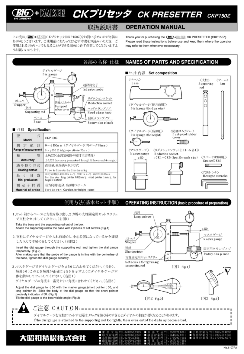
인선 방향 각도 조정 ADJUSTING THE CUTTER HEAD THROUGH 360°
4
위치 결정 핀과 인선 방향 각도 조정 (노크 핀으로 고정)
ADJUSTING THE CUTTER HEAD (Fixing by knock pin)
각도 고정은 인선 방향 조정 볼트만으로 충분하지만진동을 동반한가공등 인선 방향에 변위가 발생할 경우,
노크 핀을 삽입하면 더욱 완벽하게 헤드를 고정 할 수 있습니다.
・
인선 방향 설정후헤드 케이스 플랜지면에 있는 부쉬를 가이드로 플랜지에 노크 핀 홀 가공을 합니다.
가공 깊이는 부쉬 단면에서 28mm이내로 하여 주십시오. (부속된 노크핀에는 제거용 나사가 있으므로
장착시 방향에 주의 하십시오.)
노크핀 삽입후에도 인선 방향 조정 볼트 및 고정 볼트는 체결한 상태에서가공을 하십시오.
①
②
SIDE LOCK BOLT
고정 볼트 BUSH/PIN
인선 방향 고정용 부쉬
ADJUSTING BOLT
인선 방향 조정 볼트
28
CAUTION주 의
노크핀 홀의 가공에 대해,
가공후 미세 조정은 할 수 없으므로, 가공전에 인선 방향의 확인을 충분히 수행하여 주십시오.
가공하기 전에 반드시 인선 방향 조정 볼트가 완벽하게 조여 있는지를 확인하여 주십시오.
가공중에 앵글 헤드가 파손될 수 있습니다.
・
・
For added rigidity, under heavier cutting condition, it is always recommend that the knock pin be utilized after
adjusting the cutter head direction to the required position certainly.
・
Make the hole by utilizing Bush, in a head after adjustment. The depth of hole has to be 28mm or less. Insert the
knock pin with correct direction, because it has a tap for removal. (Outside diameterφ6h7)
Tighten the Side Lock Bolt and Adjusting Bolt securely.
①
②
It is not able to do the adjustment of the head after the knock pin is inserted, so confirm the direction of the head
before knock pin hole processing.
Please confirm tightening of the ADJUSTING BOLT without fail, when the knock pin is used. In case of this
procedure is failed, it may cause to breakage of ANGLE HEAD.
・
・
No.0420
■본사 
■기 술 부 
(+81)-72-982-8277
[email protected]

This manual suits for next models

2

Other Big Daishowa Industrial Equipment manuals

Big Daishowa BBT30 User manual

Big Daishowa

Big Daishowa BBT30 User manual

Big Daishowa SMART DAMPER User manual

Big Daishowa

Big Daishowa SMART DAMPER User manual

Big Daishowa PERFECT SEAL User manual

Big Daishowa

Big Daishowa PERFECT SEAL User manual

Big Daishowa BBT 40 User manual

Big Daishowa

Big Daishowa BBT 40 User manual

Big Daishowa BBT30 User manual

Big Daishowa

Big Daishowa BBT30 User manual

Big Daishowa BASE MASTER mini User manual

Big Daishowa

Big Daishowa BASE MASTER mini User manual

Big Daishowa C-CUTTER User manual

Big Daishowa

Big Daishowa C-CUTTER User manual

Big Daishowa BBT30 User manual

Big Daishowa

Big Daishowa BBT30 User manual

Big Daishowa FCR 16 User manual

Big Daishowa

Big Daishowa FCR 16 User manual

Big Daishowa BASE MASTER User manual

Big Daishowa

Big Daishowa BASE MASTER User manual

Big Daishowa Point Master PMC-20S User manual

Big Daishowa

Big Daishowa Point Master PMC-20S User manual

Big Daishowa HMC20S-NRA User manual

Big Daishowa

Big Daishowa HMC20S-NRA User manual

Big Daishowa NEW BABY CHUCK User manual

Big Daishowa

Big Daishowa NEW BABY CHUCK User manual

Big Daishowa FCR16 User manual

Big Daishowa

Big Daishowa FCR16 User manual

Big Daishowa KAISER CK PRESETTER User manual

Big Daishowa

Big Daishowa KAISER CK PRESETTER User manual

Big Daishowa C-CUTTER MINI User manual

Big Daishowa

Big Daishowa C-CUTTER MINI User manual

Popular Industrial Equipment manuals by other brands

Kessler TSM user manual

Kessler

Kessler TSM user manual

ABB HT606680 Operation manual

ABB

ABB HT606680 Operation manual

SMC Networks ZXP7 11 X1 Series Operation manual

SMC Networks

SMC Networks ZXP7 11 X1 Series Operation manual

Little Machine Shop HiTorque 3990 user guide

Little Machine Shop

Little Machine Shop HiTorque 3990 user guide

Slee MICROTOME CUT 5062 operating manual

Slee

Slee MICROTOME CUT 5062 operating manual

Hunter ST-1700V owner's manual

Hunter

Hunter ST-1700V owner's manual

Viking pump 3-551-050-276 Technical & service manual

Viking pump

Viking pump 3-551-050-276 Technical & service manual

Rodix FEEDER CUBE FC-40 Plus Series Adjustments and Set Up

Rodix

Rodix FEEDER CUBE FC-40 Plus Series Adjustments and Set Up

Aircycle Bulb Eater VRS Premium manual

Aircycle

Aircycle Bulb Eater VRS Premium manual

KYOWA LCH instruction manual

KYOWA

KYOWA LCH instruction manual

BVA Hydraulics JU506 manual

BVA Hydraulics

BVA Hydraulics JU506 manual

SUGATSUNE ZweiL Series instruction manual

SUGATSUNE

SUGATSUNE ZweiL Series instruction manual

Nexen Air Champ TSE-800-1 instructions

Nexen

Nexen Air Champ TSE-800-1 instructions

Salda AVS Series Mounting and installation instructions

Salda

Salda AVS Series Mounting and installation instructions

Sony PL101 Series instruction manual

Sony

Sony PL101 Series instruction manual

Javo Compact manual

Javo

Javo Compact manual

ABB XAC24806 Operation manual

ABB

ABB XAC24806 Operation manual

Rittal S22 operating instructions

Rittal

Rittal S22 operating instructions

manuals.online logo
manuals.online logoBrands
  • About & Mission
  • Contact us
  • Privacy Policy
  • Terms and Conditions

Copyright 2025 Manuals.Online. All Rights Reserved.