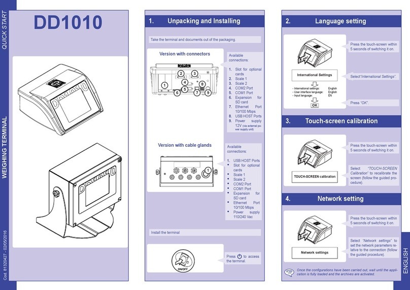
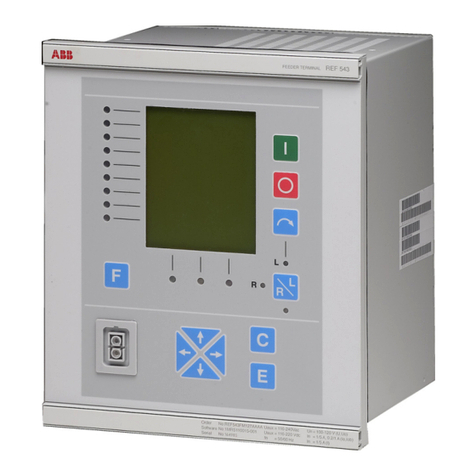
Bilanciai DD2060 X Series User manual

TERMINAL DD2060 X SERIES
USE AND MAINTENANCE MANUAL
Edition 15/09/2018
Manual code n°81320545


3
DD2060 USE AND MAINTENANCE MANUAL
TABLE OF CONTENTS
1GENERAL MATTERS ................................................................................................................... 5
1.1 Foreword............................................................................................................................................5
1.2 Documentation...................................................................................................................................6
1.3 Symbols.............................................................................................................................................6
1.4 Description of the terminal .................................................................................................................7
1.5 Specifications of the terminal.............................................................................................................8
1.6 Declaration of Conformity ..................................................................................................................9
1.7 Overall dimensions and weight of terminal ........................................................................................9
1.7.1 Wall-mounted version..........................................................................................................9
1.7.2 Version with stand .............................................................................................................10
1.7 Disposal of electrical and electronic wastes (WEEE).......................................................................11
1.8 How to obtain technical assistance..................................................................................................11
1.9 Warranty ..........................................................................................................................................11
2SAFETY RULES.......................................................................................................................... 12
2.1 Prohibited uses ................................................................................................................................12
2.2 Standards ........................................................................................................................................12
2.3 Instructions for use ..........................................................................................................................12
3DELIVERY AND INSTALLATION............................................................................................... 13
3.1 Connecting the terminal to the mains ..............................................................................................16
3.1.1 Earth connection................................................................................................................16
3.1.2 Terminal power connections..............................................................................................17
3.2 Connecting the terminal to the weighing platform............................................................................18
3.2.1 Equipotentiality between the terminal and the platform scale............................................18
3.2.2 Connecting analogue cells ................................................................................................18
3.2.3 Connecting digital cells......................................................................................................19
3.3 Connecting serial outputs ................................................................................................................20
3.3.1 Connecting the COM 5, 6, 7, 8 serial outputs....................................................................20
3.3.2 Connecting the COM 9, 10, 7, 8 serial outputs..................................................................21
3.4 External keyboard............................................................................................................................21
3.5 Inputs/Outputs .................................................................................................................................22
4CONTROLS - TURNING ON AND OFF...................................................................................... 24
4.1 Terminal power supply.....................................................................................................................24
4.2 CPU ON/OFF key ............................................................................................................................25
5. USING THE TERMINAL.............................................................................................................. 26
6. OPTIONS ..................................................................................................................................... 27
6.1 Audio amplifier.................................................................................................................................27
6.2 Printer ..............................................................................................................................................27
6.2.1 Inserting the paper roll.......................................................................................................27
6.3 Scanners..........................................................................................................................................28

4
DD2060 USE AND MAINTENANCE MANUAL

5
DD2060 USE AND MAINTENANCE MANUAL
1 GENERAL MATTERS
1.1 Foreword
•The purpose of this manual is to inform the operator, by means of texts and figures, of the
basic rules and criteria which must be observed to correctly install, safely use and regularly
maintain the weighing unit.
•This manual must be kept in a safe place where it is readily available for consultation! Always
observe the instructions contained in the manual!
•Safe operation of the system is entrusted firstly to the operator who must possess sufficient
knowledge of the former.
•The user is responsible for making sure that the installation complies with the relative
standards in force.
•The equipment must be installed by qualified personnel after reading and understanding the
contents of this manual.
•“Qualified personnel” means persons that have received sufficient training and have acquired
enough professional experience to be authorised by the "Person in charge of safety" to
perform installation, use and maintenance work.
•Contact your nearest Service Centre if problems occur.
•Neither the user nor unauthorised personnel must attempt to disassemble, modify and
tamper with the system; in this event, the warranty will be immediately invalidated and the
Manufacturer may not be held liable for any damage to people or property.
•For no reason may the information on the nameplate, seals and legalization stamps be
altered; as a consequence, make sure that all plates and labels are readable and, on the
contrary, contact the After Sales Office.
•The manufacturer shall not be liable for any damages caused by incorrect handling of the
terminal.
•The information and illustrations contained in this document are updated as at the date of
issue.
•The Manufacturer is committed to constantly improving its products, therefore some
components of the system or parts of the software may be modified.
•All the technical information contained in this manual remains the exclusive property of the
manufacturer and may not be disclosed to third parties.
•No part of this manual may be reproduced and/or disclosed, either entirely or partially in any
form or by any means, including hard copies, electronic copies or through the Web, without
the written permission of the Manufacturer
•It is also forbidden to use this manual for any purpose that is not strictly related to the
installation, use and maintenance of the terminal.
•For the purpose of providing extensive and clear details concerning operation, adjustment
and other topics, some illustrations may show the weighing system without its guards. Never
use the system in these conditions! Remove the guards only for the time strictly necessary to
perform repair or maintenance work and refit them as soon as possible.

6
DD2060 USE AND MAINTENANCE MANUAL
1.2 Documentation
Standard documentation supplied with the DD2060 terminal consists of:
•QUICK START
multi-language, hard copy, quick reference guide for immediate use, declaration of conformity
and main hazard information.
•USE AND MAINTENANCE MANUAL
Multi-language, PDF, hard copy available upon demand.
•INSTALLATION MANUAL
Multi-language, PDF, hard copy available upon demand.
Contact the After Sales Office of our Sales and Service network.
1.3 Symbols
Here below are the symbols used in the manual to draw the operators' attention to the various
danger levels relating to “Use and Maintenance” of the instrument.
DANGER
Denotes an operation or procedure where failure to observe the instructions will result in
death or serious injury.
ATTENTION
Denotes an operation or procedure where failure to observe the instructions could result in
minor injury or damage to the instrument.
WARNING
Information or procedure that the operator must follow to ensure correct use of the system,
extend its service life, prevent damage or loss of programming or optimise operation in
compliance with metric standards.
TECHNICAL SUPPORT
The sections bearing this pictogram must be entrusted to the qualified technician provided
by the manufacturer for the purpose of performing particularly complex work in special
conditions. Specialised mechanical and/or electric and/or software technicians are
available according to need. PERFORMING THESE OPERATIONS IS STRICTLY
PROHIBITED! DANGER OF ACCIDENTS OR DAMAGE TO MACHINE!

7
DD2060 USE AND MAINTENANCE MANUAL
1.4 Description of the terminal
The DD2060 terminal performs highly accurate and reliable weighing. Its main purposes are
weighing vehicles and performing commercial weighing operations. The monitor and
alphanumeric keyboard make it ideal for inexpert operators.
Some of the main characteristics of the indicator are listed below:
•it can be connected to 4 scales with load cells at the most (up to 12 x 350 Ohm analogue
cells for reach scale input)
•it can be connected to 4 scales with digital load cells at the most (up to 12 CPD digital
cells for 1 scale input, max. 16 cells for all scales)
o4 RS232 serial outputs
o2 RS422 serial outputs
o7 inputs and 7 outputs
oUSB port
o1 Vga port
o1 HDMI port
oPower supply 110-240 VAC
o2 Ethernet ports
It can also be connected to the keyboard of a compatible PC.
Upon demand, extra cards may be added for interfacing the indicator and for expanding the
system.

8
DD2060 USE AND MAINTENANCE MANUAL
1.5 Specifications of the terminal
Power supply
110-240 VAC, 50/60 Hz
12 VDC
Load cells that can be
connected
up to 12 x 350 Ohm analogue cells on the 9-pin connector for each
scale input
Up to 12 CPD digital cells on the 15-pin connector for 1 scale input
(in the event of duplex installation, up to 8 cells per input)
Minimum impedance
29 Ohm (per analogue input)
Analogue load cell power
9-10 VDC
Digital cell power
10 – 18 VDC
Internal resolution
500000 counts @ 25 conv./sec.
120000 counts @ 100 conv./sec.
Resolution in type-
approved version
Resolution in type-approved version
max. 6000 divisions per interval, Class III
4000 per multi-interval/field (2 partial fields), Class III
3000 per multi-interval/field (3 partial fields), Class III
1000 per single and multi-interval/field (2 and 3 partial fields), Class
III
Maximum input signal
23 mV
Sensitivity
0.6 uV/division (version with analogue cells)
Full scale stability
< 5 ppm/°C
Zero stability
< 5 ppm/°C
Compensated
temperature range
-10 + 40 °C
Operating range
-15 + 50 °C
Protection rating
With the cover supplied, it can withstand adverse weather conditions
Maximum humidity
85 % @ 40°C
Maximum I/O output
voltage
24 VAC/DC
Maximum I/O output
current
190 mA max.
External keyboard input
USB
Display
12.1” TFT colour display
Touch screen
Capacitive, Sunlight version
Printer (upon demand)
80 mm thermal type
Scanner (upon demand)
RFID, Barcode, magnetic, depending on model

9
DD2060 USE AND MAINTENANCE MANUAL
1.6 Declaration of Conformity
See QUICK START manual.
1.7 Overall dimensions and weight of terminal
1.7.1 Wall-mounted version
Figure 1.1 - Overall dimensions of the wall-mounted terminal
Weight:
25 kg
Measurements are given in millimetres.

10
DD2060 USE AND MAINTENANCE MANUAL
1.7.2 Version with stand
Figure 1.2 - Overall dimensions of the terminal with stand
Weight:
25 kg
Measurements are given in millimetres.

11
DD2060 USE AND MAINTENANCE MANUAL
1.7 Disposal of electrical and electronic wastes (WEEE)
The following symbol means that:
•the product must n
ot be handled as municipal waste and must be
disposed of separately;
•
the product may be handed over to the dealer upon purchasing a new
and similar piece of equipment;
•
the user must contribute to correct recycling. Improper use and
disposal may be cause of environmental pollution or health hazards;
•failure to fulfil the above provisions will be sanctioned under the laws in
force.
1.8 How to obtain technical assistance
Should the instrument work improperly or should there be faults calling for the work of qualified
technicians, contact the nearest service centre of the manufacturer directly.
To obtain a quicker reply, always provide the serial number of the instrument that can be found
on the stamped plate.
Also provide information on the system in which the terminal has been installed.
1.9 Warranty
Warranty conditions are set forth in the sales contract.

12
DD2060 USE AND MAINTENANCE MANUAL
2 SAFETY RULES
2.1 Prohibited uses
The instrument you have purchased is a weighing system and has been designed and
manufactured as such.
Its main purpose is therefore weighing goods.
•It is forbidden to use the terminal without taking the necessary precautions for safe use.
•Use of the terminal in potentially explosive atmospheres or in areas where there is a risk of
fire is strictly prohibited.
Other uses are allowed only if explicitly authorised by the manufacturer.
2.2 Standards
The operating conditions for the electronic terminal are subject to the regulations in force in the
country in which the terminal is used.
Use in conditions not complying with these standards is prohibited.
2.3 Instructions for use
•When using the instrument, strictly follow the instructions in this manual.
•Should you find differences between the contents of this manual and the instrument you have
purchased, contact your retailer or the After Sales office of the manufacturer.
•Always observe the indications given on the warning and danger plates on the terminal.
•Make sure that all guards are fitted and make sure cables are in good repair and correctly
connected.
•Ensure that the terminal is plugged into a socket with an efficient earth connection and make
sure that the latter complies with the standards in force. Check that there is no difference in
potential between earth and neutral conductors.
•If the terminal is to be connected to other devices (e.g. a computer), these devices must be
disconnected from the electrical supply before connection to the terminal.
•All maintenance work and/or repairs must be carried out by authorised personnel only.
•Always disconnect the terminal from the electricity main and wait a few minutes before
gaining access to the internal components.

13
DD2060 USE AND MAINTENANCE MANUAL
3 DELIVERY AND INSTALLATION
Figure 3.1 – Inside of the board
Key:
1. CPU box
2. 12V power supply (logic)
3. 24V power supply (printer and heater)
4. Main switch
5. Thermostat card
6. Amplifier (optional)
1
2
3
4
6
5

14
DD2060 USE AND MAINTENANCE MANUAL
Figure 3.2 – Block diagram

15
DD2060 USE AND MAINTENANCE MANUAL
Figure 3.3 – CPU box: view from below
Figure 3.4 – CPU box: side view
Key:
1Scale A, B, C, D
26 x COM RS232/422 serial ports (starting from left “COM8, COM7, COM6, COM5, COM10,
COM9”)
34 x USB ports
47+7 inputs/outputs 24VAC/DC.
5Power supply, 12 VDC/5A
62 Ethernet 10/100 ports
7VGA output
8HDMI output
3
8
7
6
5
4
4
2
B
C
A
D

16
DD2060 USE AND MAINTENANCE MANUAL
3.1 Connecting the terminal to the mains
Connection to the power supply line is at the installer's care. The customer must provide, by means
of qualified personnel, installation of the earth conductor and power supply cable.
3.1.1 Earth connection
Provide the earth connection for the terminal by means of a yellow-green cable with a size of at
least 6mm². Use the grounding screw inside the terminal.
Connect any equipotential conductor leading from the scale to the same earth connection point.
If the terminal is installed on a stand, secure the earth connection cable to it.
The earth connection cable and accessories for connection are not part of the supply but are at
the customer's care and charge.
Figure 3.5 – Earth connection screw

17
DD2060 USE AND MAINTENANCE MANUAL
3.1.2 Terminal power connections
Install a three-pole cable of a size that is suitable for the type of system. When choosing a cable,
make reference to the power supply specifications.
Basic characteristics of the power supply cable:
•double insulated cable with 3 coloured conductors
(line=brown, neutral=blue, earth=yellow-green)
•internal conductors with size ranging from 1.5mm² to 2.5mm²
•diameter of sheath from 5 to 10mm
DANGER
Check that:
•the voltage and frequency of the electrical supply line correspond to the indications on the
sealing plate at the bottom of the terminal;
•the mains outlet socket to which the terminal is connected is equipped with an earth;
•warning and danger plates are secured to the instrument's casing;
•on the contrary, advise maintenance staff or our Technical Service Centre.
Use the main switch to power up the terminal, as shown in the following figure.
Figure 3.6 – Powering up with the main switch
ATTENTION
The terminal complies with the European directive on electromagnetic compatibility.
However, it is always recommended to provide a separate power supply line for the
terminal.
The power supply line must be installed away from signal cables (RS232,422, Ethernet,
load cell cable).

18
DD2060 USE AND MAINTENANCE MANUAL
3.2 Connecting the terminal to the weighing platform
3.2.1 Equipotentiality between the terminal and the platform scale
Check that a condition of equipotentiality exists between the metal parts of the terminal and the
platform scale.
If you have any doubts, connect the terminal and the platform using an earth connection cable
with a size of at least 6mm², using the earth connection screw at the bottom of the terminal.
The cables required for this connection are to be provided by the customer.
3.2.2 Connecting analogue cells
9-pin male connector.
Key:
NC = do not connect
SIG + = + signal
SIG - = - signal
EX + = + power supply
EX - = - power supply
SENSE + = SENSE signal +
SENSE - = SENSE signal -
Figure 3.7 - Diagram for connection to platforms fitted with analogue load cells

19
DD2060 USE AND MAINTENANCE MANUAL
3.2.3 Connecting digital cells
15-pin female connector
Key:
EX + = + power supply
EX - = - power supply
DATA +/- = Bidirectional data lines
NC = do not connect
Figure 3.8 - Diagram for connection to platforms fitted with digital load cells
Connection towards digital cells is ensured to RS485 serial transmission using a shielded cable
with 6 wires.
Pins with the same signal can be parallelised.

20
DD2060 USE AND MAINTENANCE MANUAL
3.3 Connecting serial outputs
The RS232 serial outputs are COM 5, 6, 7, 8 whereas the RS422 are 9 and 10.
3.3.1 Connecting the COM 5, 6, 7, 8 serial outputs
9-pin female connector
Key:
PIN5>GND
PIN2>RX
PIN3>TX
Figure 3.9 - COM 5, 6, 7, 8 connection diagram (9-pin sub D)
ATTENTION
Max. conditions of usage under RS232 standard:
Max. transmission distance: 15 m
Maximum voltage at ends: ± 12 VDC
For connection to external devices, it is recommended to use a shielded cable, making sure to
connect the shield to the metal part of the 9-pin connector's casing.
Other manuals for DD2060 X Series
1
Table of contents
Other Bilanciai Touch Terminal manuals
Bilanciai
Bilanciai DD1010 User manual
Bilanciai
Bilanciai D450 User manual
Bilanciai
Bilanciai D440IS Assembly instructions
Bilanciai
Bilanciai D410 User manual

Bilanciai
Bilanciai DD2060 X Series User manual

Bilanciai
Bilanciai D800 User manual
Bilanciai
Bilanciai D400 User manual

Bilanciai
Bilanciai D400 User manual
Bilanciai
Bilanciai PS440 Series User manual
Bilanciai
Bilanciai D70E User manual
