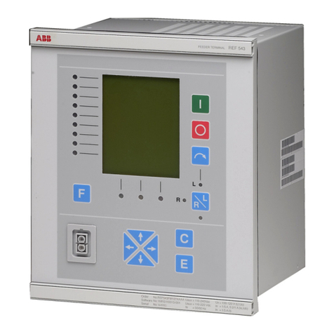
Bilanciai PS440 Series User manual

Terminal D440IS and power supplier
PS440/xxx –PS440-A/xxx
USE AND MAINTENANCE MANUAL
Manual code n° 81320122 Edition 05/11/2018


3
DS440IS
TABLE OF CONTENTS
1GENERAL MATTERS...................................................................................................................7
1.1 Declaration of conformity...................................................................................................................7
1.2 Foreword............................................................................................................................................7
1.3 Symbols.............................................................................................................................................8
1.4 Documentation...................................................................................................................................9
1.5 ATEX certification ............................................................................................................................10
1.6 Description of the terminal...............................................................................................................10
1.6.1 Versions ............................................................................................................................11
1.6.2 Options..............................................................................................................................11
1.7 Specifications of the terminal...........................................................................................................12
1.7.1 Terminal D440IS................................................................................................................12
1.7.2 Power supplier PS440/xxx.................................................................................................13
1.7.3 Power supplier PS440-A/xxx.............................................................................................13
1.8 Dimensions and weight of the terminal............................................................................................14
1.9 Obtaining technical assistance ........................................................................................................17
1.10 Warranty..........................................................................................................................................17
2SAFETY INSTRUCTIONS...........................................................................................................18
2.1 Prohibited uses................................................................................................................................18
2.2 Regulations......................................................................................................................................18
2.3 Recommendations for installation....................................................................................................18
2.3.1 Classification of zones and substances.............................................................................18
2.3.2 Compatibility......................................................................................................................19
2.3.3 Surface or underground.....................................................................................................19
2.3.4 Categories of equipment ...................................................................................................19
2.3.5 Groups of substances and surface temperatures..............................................................20
2.3.6 IP protection degree and surface temperature..................................................................20
2.3.7 Description of the system installed....................................................................................20
2.4 Prescriptions of use .........................................................................................................................21
3DOCUMENT DESCRIBING THE SYSTEM ................................................................................22
3.1 Foreword..........................................................................................................................................22
3.2 Specifications of the components used ...........................................................................................22
3.2.1 PS440/xxx –PS440-A/xxx.................................................................................................22
3.2.2 D440IS ..............................................................................................................................22
3.2.4 12x0.35 mm² power supplier-terminal connection cable....................................................23
3.2.5 6x0.5 mm² cable for the cells, inputs/outputs, analogue output.........................................23
3.2.6 Optical fibre .......................................................................................................................23
3.3 Sizing the system.............................................................................................................................24
3.3.1 PS440/xxx D440IS connection..........................................................................................24
3.3.2 Connection of the D440IS scale - Load cells type Eurocell IS/xxx ....................................24
3.3.3 Connection of D440IS - clean contact inputs.....................................................................24
3.3.4 Connection of PS440/xxx Clean contact outputs towards safe zone.................................24
3.3.5 Connection of PS440-Axxx - Output Exi............................................................................24
3.3.6 Connection of D440IS - 4-20mA analogue output.............................................................24
3.3.7 Optical fibre connection ..........................................................................................................25
3.4 Global protection characteristics of the system................................................................................25
3.4.1 For ambient temperatures of up to +40°C.........................................................................25
3.4.2 For ambient temperatures of up to +55°C.........................................................................25
4DELIVERY AND INSTALLATION...............................................................................................26
4.1 Accesses .........................................................................................................................................26
4.1.1 D440IS accesses...............................................................................................................26
4.1.2 PS440/xxx power supplier accesses.................................................................................27
4.1.32 PS440-A/xxx power supplier accesses..............................................................................27
4.2 Connection of the terminal to the electrical supply line....................................................................28
4.3 Opening the terminal for access to the internal terminals................................................................34
4.3.1 Internal terminal connections.............................................................................................37
4.4 Connection to the external devices..................................................................................................38
4.5 Connection of the terminal to the platform scale..............................................................................39
4.5.1 Analogue cell connection...................................................................................................40
4.6 Output connection............................................................................................................................41

4
DS440IS
4.7 Input/Output connection...................................................................................................................43
4.8 How to test the system ....................................................................................................................45
4.8.1 Verification of the compatibility of the system....................................................................45
4.8.2 How to check the installation.............................................................................................46
4.8.3 How to check the documentation.......................................................................................47
5CONTROLS, DISPLAY, SWITCHING THE TERMINAL ON AND OFF.....................................48
5.1 Display of weight and additional information....................................................................................48
5.1.1 Selection display symbols .................................................................................................50
5.2 Weighing function keys....................................................................................................................51
5.3 Alphanumeric keys ..........................................................................................................................53
5.4 Switching the terminal on and off.....................................................................................................54
6. USING THE TERMINAL..............................................................................................................56
6.1 GENERAL MATTERS .....................................................................................................................56
6.1.1 Using the keys to navigate the menus...............................................................................56
6.1.2 Entering numeric data (Editor)...........................................................................................57
6.1.3 Entering alphanumeric data...............................................................................................57
6.1.4 Shortcut keys.....................................................................................................................59
6.2 User menu.......................................................................................................................................60
6.2.1 Adjusting the contrast........................................................................................................60
6.2.2 Changing the date and time ..............................................................................................60
6.2.3 Weight display...................................................................................................................60
6.2.4 Memory status...................................................................................................................63
6.2.5 Reprint...............................................................................................................................63
6.2.6 Setting the outputs as Setpoints (if enabled).....................................................................63
6.2.7 Setting the outputs as ranges (if enabled) ..............................................................................64
6.2.8 Generic code.....................................................................................................................64
6.2.9 Product code .....................................................................................................................65
6.2.10 Product code list................................................................................................................66
6.2.11 Preset tares.......................................................................................................................67
6.2.12 Preset tare list....................................................................................................................68
6.2.13 Progressive number ..........................................................................................................69
6.2.14 Coefficient Management....................................................................................................69
6.2.15 Extraction data...................................................................................................................69
6.2.16 Totals management...........................................................................................................70
6.2.17 User menu access.............................................................................................................71
6.2.18 Weighing operation............................................................................................................71
6.3 Printing weighing data .....................................................................................................................72
6.3.1 Weighing data reprint ........................................................................................................73
6.3.2 Automatic print-out ............................................................................................................73
6.4 Operating modes.............................................................................................................................74
6.5 Standard operation..........................................................................................................................74
6.6 Loading extraction operation............................................................................................................74
6.7 Unloading extraction operation........................................................................................................75
6.8 Extraction on loading with fall management.....................................................................................75
6.8.1 Operating data...................................................................................................................75
6.8.2 Extraction totals.................................................................................................................77
6.8.3 START key........................................................................................................................78
6.8.4 Data displayed with extraction activated............................................................................79
6.8.5 Operating principle of extraction........................................................................................80
6.8.6 Numeric example of an extraction cycle............................................................................81
6.8.7 Error messages.................................................................................................................82
6.9 MPP operation.................................................................................................................................82
6.10 Double weighing mode.......................................................................................................................83
6.10.1 Entrance and exit weighing ...............................................................................................83
6.11 Entry/Exit Functions with Data Recall..............................................................................................84
6.11.1 Entry weighing procedures................................................................................................84
6.11.2 Exit weighing procedures ..................................................................................................86
6.11.3 Unused RCD code recovery..............................................................................................87
6.12 Entry/Exit operations using Licence Plate Data Recall.......................................................................88
6.13 Preset weight options.........................................................................................................................89
6.13.1 How to make the list of preset weights ..............................................................................89
6.13.2 Weighing procedures with preset weights .........................................................................90
6.14 Options for entering the first weight manually..................................................................................90
6.15 Total management..............................................................................................................................91

5
DS440IS
7. OPTIONS.....................................................................................................................................92
7.1 MPP memory expansion boards......................................................................................................92
7.1.1 Memory capacity ...............................................................................................................92
7.1.2 Operation................................................................................................................................92
7.1.3 Disabling MPP...................................................................................................................93
7.1.4 Checking memorised weight data......................................................................................94
7.2 Optical fibre output option................................................................................................................94
7.2.1 Connection harness...........................................................................................................95
7.2.2 Point-to-point mode...........................................................................................................96
7.2.3 Optic loop mode ................................................................................................................96
7.2.4 Optical fibre adapter - RS232 (FO-232).............................................................................97
7.3 Printers ............................................................................................................................................98
7.3.1 Connection with STB60 in the RS232 mode .....................................................................98
7.3.2 Connection to STB112 in RS232, -TM295, TMU295, LX300+, ITALORA.........................99
7.4 Connection to a PC........................................................................................................................100
7.5 4-20 mA analogue output...............................................................................................................101
8. MAINTENANCE.........................................................................................................................104
8.1 Lithium battery...............................................................................................................................104
8.2 Casings..........................................................................................................................................104
8.3 Test of the system .........................................................................................................................104
9. TROUBLESHOOTING ..............................................................................................................106
9.1 Malfunctions...................................................................................................................................106
9.2 Error messages .............................................................................................................................107

6
DS440IS
WARNING
Document relating to CESI 00 ATEX 038, CESI 05 ATEX 022 X and CESI 05 ATEX 023
certificates.
No changes are permitted without the approval of the "Authorised Person".

7
DS440IS
1 GENERAL MATTERS
1.1 Declaration of conformity
The declaration of conformity is attached to the safety instructions enclosed with the supply.
1.2 Foreword
The aim of this manual is to provide the operator, through the use of text and illustrations, with
essential information regarding the installation, safe operation and maintenance of the weighing
system.
This manual must be kept in a safe place where it is readily available for consultation! Always
observe the instructions contained in the manual!
Safe operation of the system is entrusted firstly to the operator who must possess sufficient
knowledge of the former.
The user is responsible for making sure that installation complies with the relative standards in
force.
The equipment must be installed by qualified personnel after reading and understanding the
contents of this manual.
“Qualified personnel” means persons that have received sufficient training and have acquired
enough professional experience to be authorised by the "Person in charge of safety" to perform
installation, use and maintenance work.
Contact your nearest Service Centre if problems occur.
Any attempt on the part of unauthorised personnel to dismantle or modify the terminal is
prohibited; in this event, the warranty will be immediately invalidated and the Manufacturer may
not be held liable for any damage to people or property.
The alteration or removal of the data plates and seals is strictly prohibited; as a consequence,
make sure that all plates and labels are readable and, on the contrary, contact the After Sales
Office.
The manufacturer shall not be liable for any damages caused by incorrect handling of the
terminal.
The information and illustrations contained in this manual were up to date at the time of
publication.
The Manufacturer is committed to constantly improving its products, therefore some components
may be modified.
All the technical information contained in this manual remains the exclusive property of the
manufacturer and may not be disclosed to third parties.
No part of this manual may be reproduced and/or disclosed, either entirely or partially in any
form or by any means, including hard copies, electronic copies or through the Web, without the
written permission of the Manufacturer
It is also forbidden to use this manual for any purpose that is not strictly related to the
installation, use and maintenance of the terminal.
In order to more clearly illustrate certain maintenance or adjustment operations, some of the
illustrations in this manual show the weighing system with the safety guards removed. Never use
the system in these conditions! Remove the guards only for the time strictly necessary to
perform repair or maintenance work and refit them as soon as possible.

8
DS440IS
1.3 Symbols
Below is a list of the symbols used in this manual to alert the reader to the various hazards
associated with the operation and maintenance of the instrument.
DANGER
Denotes an operation or procedure where failure to observe the instructions will result in death or
serious injury.
CAUTION
Denotes an operation or procedure where failure to observe the instructions could result in minor
injury or damage to the instrument.
WARNING
Information or instructions on how the system is to be operated correctly in order to maximise its
service life or prevent loss or damage of programmed data or to optimise operation with regard to
metrological standards.

9
DS440IS
The hexagon-epsilon-ex symbol indicates an ATEX-certified component that can be
installed in zones with potentially explosive gas or dust. The installation is subject to
limitations established by the "CE type certificate" issued.
The triangle-capital EX symbol indicates an zone where there could be potentially
explosive gas or dust. This zone is also called "HAZARDOUS ZONE" Only simple
appliances or ones marked can be installed in this zone.
As above, but crossed. Indicates a zone where there is no potentially explosive gas or
dust. This zone is also called "SAFE ZONE".
Text and messages displayed on the terminal
are printed in this manual using special characters.
Messages:
Display messages appear like this.
Menu pathways:
2°F>OTHER>MENU>Contrast.
The character > indicates the transition from one menu option to the next.
1.4 Documentation
Use and maintenance manual: the manual you are reading.
CD ROM: contains information that mainly concerns how the terminal is installed. Here you will
find information on how to interface the weighing terminal with a PC or PLC.
Safety instructions: also called "Safety notes". Besides the ATEX declaration of conformity,
also contain instructions about how to install the equipment in hazardous zones.

10
DS440IS
1.5 ATEX certification
The terminal has been designed for installation in systems situated in places with potentially
explosive dust and/or gas.
Terminal D440IS and its power supplier PS440/xxx - PS440-A/xxx have ATEX certification.
They are connected to load cells, which are also certified, thus forming a complete weighing system
for hazardous zones.
1.6 Description of the terminal
The digital weight indicator allows highly accurate and reliable weighing. This terminal is designed to
facilitate dialogue with the operator through the alphanumeric keypad and graphic display, which, in
addition to being extremely easy to use, has facilities for changing the shape and size of the display
characters to suit various conditions of use. The terminal provides a wide range functions, which,
combined with the possibilities for expansion, allow for easy interfacing with external equipment.
Certain of the standard characteristics of the system are listed below:
installation in ZONES 1, 2, 21, 22
3 metre terminal-power supplier connection cable
connection to a scale with analogue cells (up to four 350 Ohm cells or eight 700 Ohm cells)
4 relay outputs
230 VAC power supply (or 215 VAC or 24 VAC)
specific operating modes that can be selected by the operator
connection to tape, tag and label printers installed in safe zones
management of totals files associated with alphanumeric codes
quick customisation of keypad and messages

11
DS440IS
1.6.1 Versions
The weighing terminal can be supplied in the following versions:
230 VAC mains power supply
115 VAC mains power supply
24 VAC low voltage power supply
1.6.2 Options
2 serial outputs in optical fibre
4-20 mA analogue output
WARNING
The 2 options, serial outputs and analogue outputs, are alternatives.
MPP memory expansion
Terminal-power supplier connection cable to customer's specifications (max. 10 m)
Single wall support for terminal and power supplier

12
DS440IS
1.7 Specifications of the terminal
1.7.1 Terminal D440IS
DANGER
Denotes an operation or procedure where failure to observe the instructions will result in death or
serious injury.
Power supply:
from PS440/xxx - PS440-A/xxx
Load cells connected:
up to eight 700 Ohm analogue cells
up to four 350 Ohm analogue cells
Minimum impedance:
87.5 ohm
Analogue load cell power:
by means of MAX 6V zener barrier
Internal resolution:
500000 points
Resolution in type-approved version:
up to 4000 divisions
Maximum input signal:
23 mV
Sensitivity:
0.63 uV/division
Full scale stability:
< 5 ppm/°C
Zero stability:
< 5 ppm/°C
Compensated temperature range:
-10 + 40 °C
Operating range:
-10 + 55 °C
Protection:
IP54
Humidity:
85 % @ 40 °C
Input contacts:
opto-isolated. Clean contacts are required.

13
DS440IS
1.7.2 Power supplier PS440/xxx
PS440/230 VAC power supply
Standard version
230 VAC (+10% -15%)
50/60 Hz
Pn = 20 VA
On Exe terminals
PS440/115 Vac
115 VAC version
115 VAC (+10% -15%)
50/60 Hz
Pn = 20 VA
On Exe terminals
PS440/24 Vac power supplier
Version with very low safety voltage
24 VAC (+10% -15%)
50/60 Hz
Pn = 20 VA
On Exe terminals
Output contacts on Exi terminals
Vmax = 125 VAC/DC
Imax = 200 mA
1.7.3 Power supplier PS440-A/xxx
PS440-A/230 VAC power supply
Standard version
230 VAC (+10% -15%)
50/60 Hz
Pn = 20 VA
On Exe terminals
PS440-A /115 VAC power supplier
115 VAC version
115 VAC (+10% -15%)
50/60 Hz
Pn = 20 VA
On Exe terminals
Output contacts on Exi terminals
Vmax = 13.4 VAC/DC
Imax = 79 mA

14
DS440IS
1.8 Dimensions and weight of the terminal
Weight: 4 kg
The dimensions are given in mm.
Figure 1.1 - Dimensions and weight of the wall-mounted terminal version

15
DS440IS
Weight: 4 kg
The dimensions are given in mm.
Figure 1.2 - Dimensions and weight of table top version

16
DS440IS
Weight: 9 kg
The dimensions are given in mm.
Figure 1.3 - Overall dimensions and weight of the terminal and power supplier on a single
wall support

17
DS440IS
1.9 Obtaining technical assistance
In the event of any operating faults requiring the intervention of specialised technicians, contact the
manufacturer or your nearest Service Centre.
To enable us to deal with your request swiftly, always quote the serial number of your terminal,
which can be found on the seal label.
Also provide information about the system in which the terminal is installed.
1.10 Warranty
The conditions of warranty are stipulated in the contract of sale.

18
DS440IS
2 SAFETY INSTRUCTIONS
2.1 Prohibited uses
The instrument you have purchased is a weighing system and has been designed and manufactured
as such.
The instrument is primarily intended for the weighing of goods.
It is forbidden to use the terminal without taking the necessary precautions for safe use.
Any other use shall only be permitted if expressly authorised by the Manufacturer.
2.2 Regulations
The operating conditions for the electronic terminal are subject to the regulations in force in the
country in which the terminal is used.
All use of the terminal in conditions which do not comply with these regulations is prohibited.
2.3 Recommendations for installation
2.3.1 Classification of zones and substances
The terminal-power supplier, load cells, connection cable system must be approved for installation in
the zone of use.
The user customer must therefore analyse and classify the hazardous zones and dangerous
substances present.
CAUTION
The Manufacturer does not classify zones and substances.

19
DS440IS
2.3.2 Compatibility
Once the zones and substances have been classified, the equipment can be chosen with protection
systems suitable for these zones/substances.
2.3.3 Surface or underground
The weighing instruments described in this manual are suitable for use on the surface (group II).
2.3.4 Categories of equipment
The appliances are classified in categories, depending on their safety (1, 2, 3).
There is also a breakdown in equipment for the presence of dust (D = Dust) and gas (G = Gas).
Danger zone
Categories under Directive
ATEX 2014/34/UE
Equipment Protection Level
Gas, mist or vapours
Zone 0
1G
Ga
Gas, mist or vapours
Zone 1
1G or 2G
Ga or Gb
Gas, mist or vapours
Zone 2
1G, 2G or 3G
Ga, Gb or Gc
Dust
Zone 20
1D
Da
Dust
Zone 21
1D or 2D
Da or Db
Dust
Zone 22
1D, 2D or 3D
Da, Db or Dc

20
DS440IS
2.3.5 Groups of substances and surface temperatures
The gases present are classified according to the energy and firing temperature (IIC, IIB, IIA and T6....T1).
2.3.6 IP protection degree and surface temperature
The casings of appliances installed where dust is present must also possess a certain IP protection degree
with a declared maximum surface temperature. This latter must be compatible with the dust ignition
temperature.
2.3.7 Description of the system installed
To facilitate the installation operations and make it easier to check whether the electrical and mechanical
parameters of the various parts forming the system are compatible with the surrounding conditions
(presence of gas and dust), the Manufacturer provides certain typical systems as described below. The
components of these systems are described and their compatibility is guaranteed.
DANGER
The customer must check to make sure that these systems are compatible with the zones and
substances in his application.
This manual suits for next models
2
Table of contents
Other Bilanciai Touch Terminal manuals
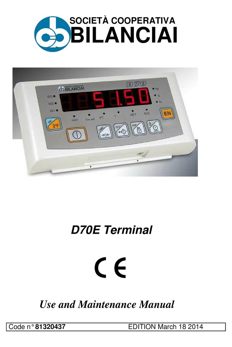
Bilanciai
Bilanciai D70E User manual
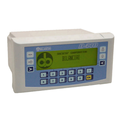
Bilanciai
Bilanciai D410 User manual
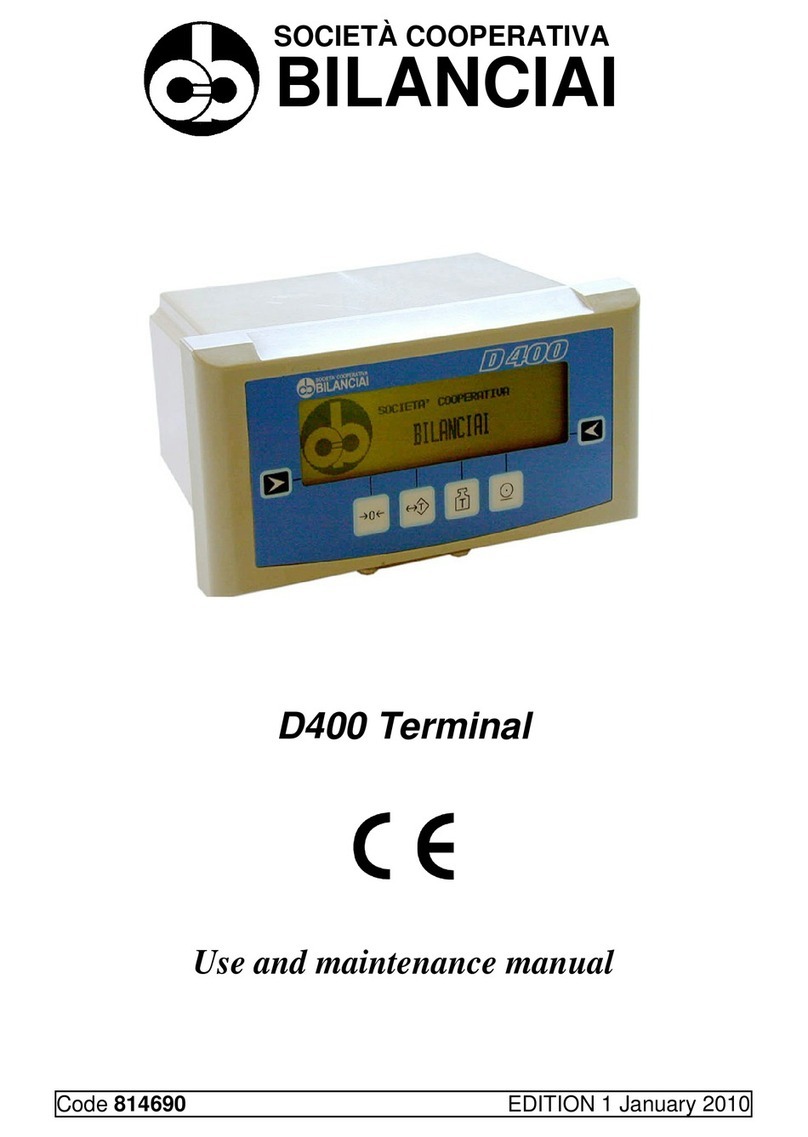
Bilanciai
Bilanciai D400 User manual
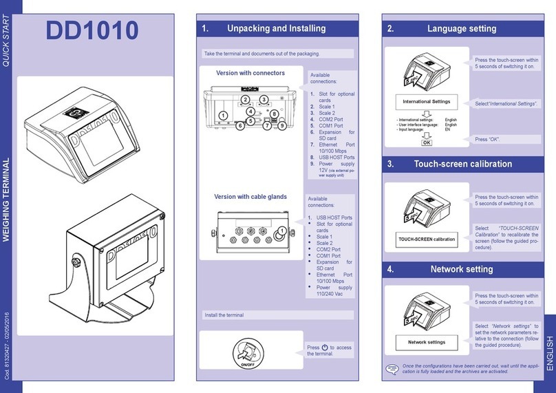
Bilanciai
Bilanciai DD1010 User manual
Bilanciai
Bilanciai D800 User manual
Bilanciai
Bilanciai DD2060 X Series User manual
Bilanciai
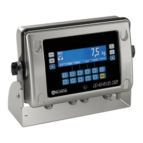
Bilanciai D440IS Assembly instructions

Bilanciai
Bilanciai D400 User manual
Bilanciai
Bilanciai D450 User manual
Bilanciai
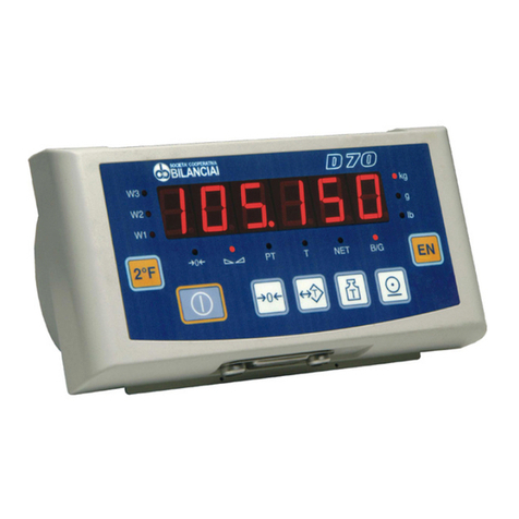
Bilanciai D70 User manual

