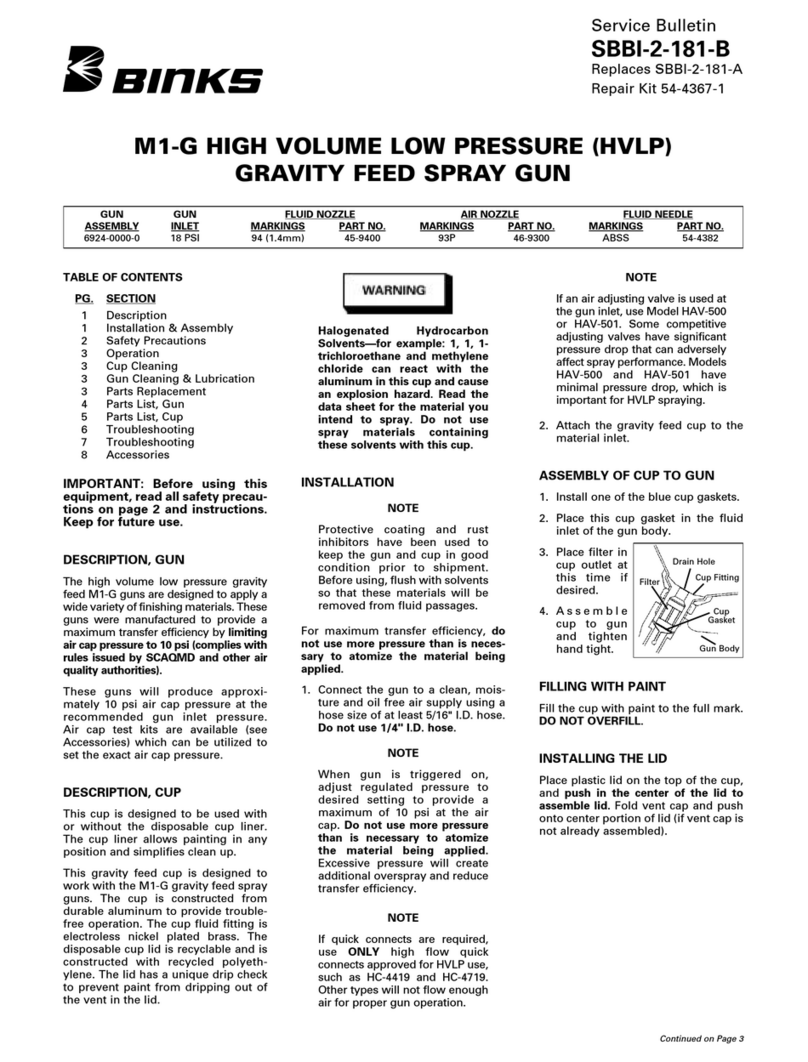
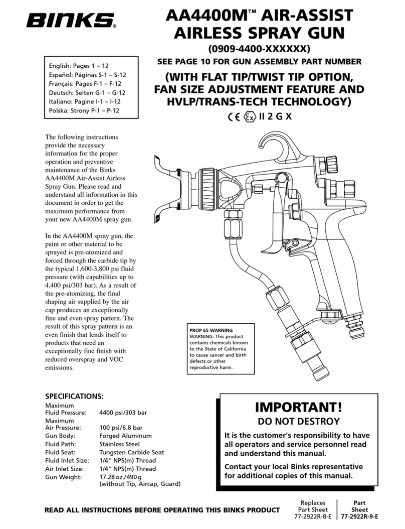
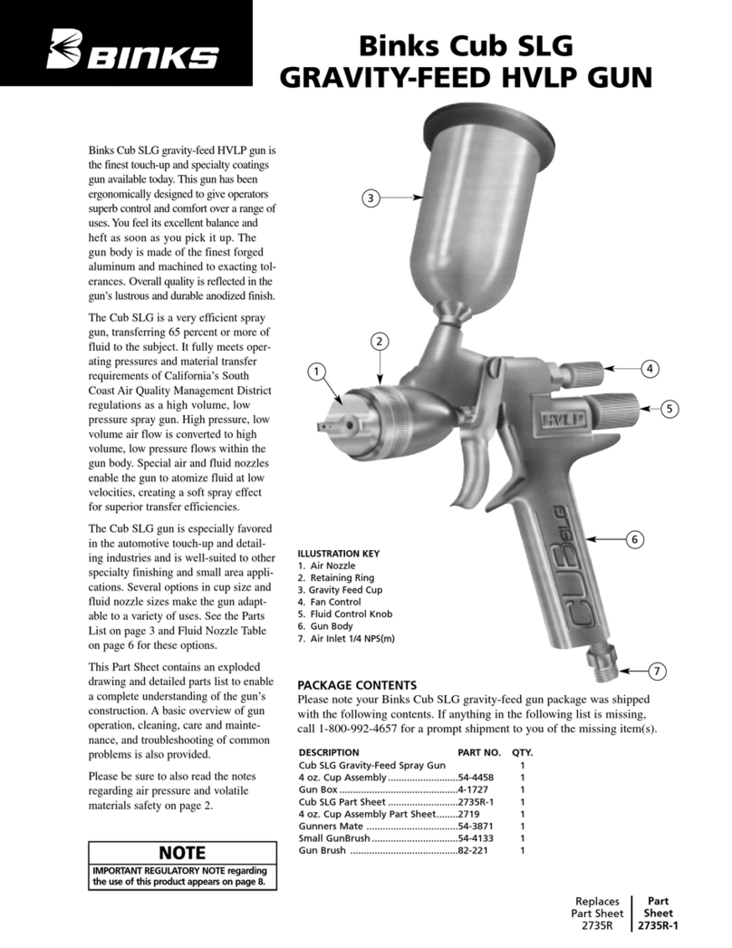
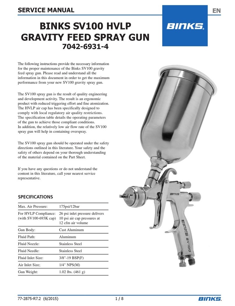
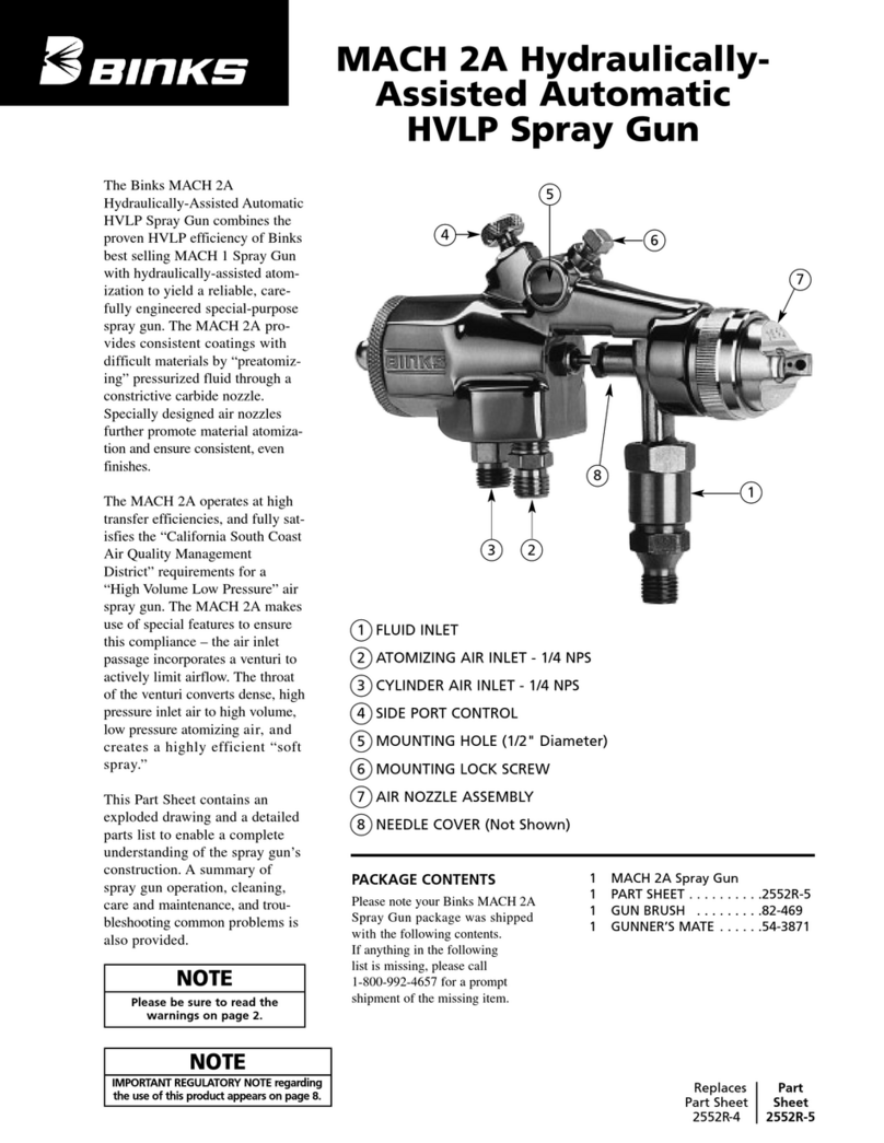
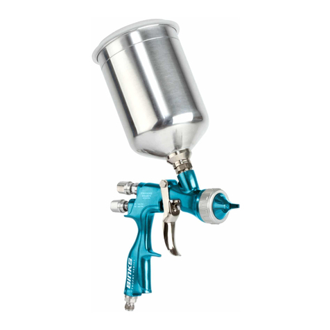
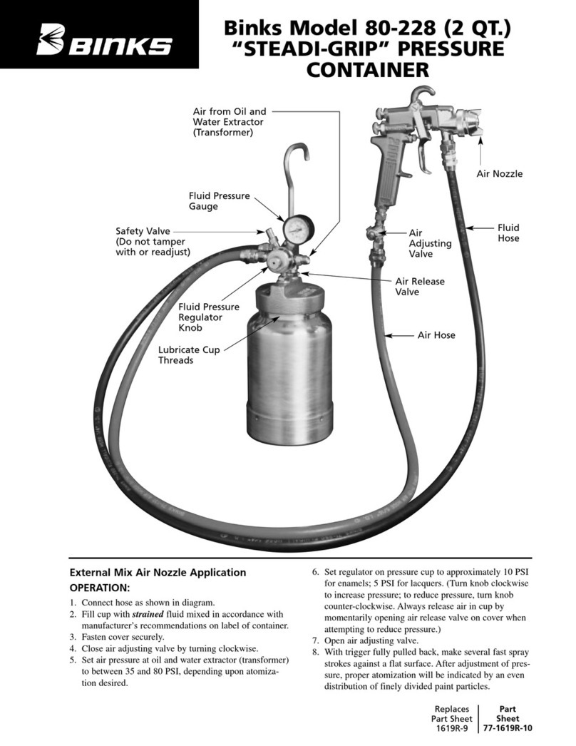
Binks 95SL User manual

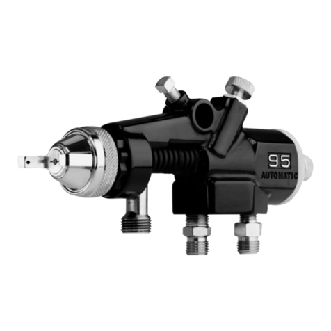
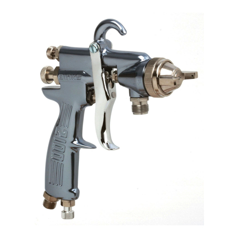
Binks’ 95SL spray gun is the latest
innovation in the 95 model line
of spray guns. The 95SL is slim
and streamlined, and weighs less
than other models. These features
make this product the gun of
choice for smaller grips and
lighter handling.
The 95SL is a high production
gun with stainless steel fluid
passages and can be used with
most coatings. The gun body is
drop-forged anodized aluminum.
Fluid passages are of stainless
steel. The 95SL features:
• an adjustable, floating needle
valve
• a stainless steel or tungsten
carbide fluid nozzle
• a self-centering air nozzle
• a brass air-valve cartridge
• light weight (about 1 lb., 4 oz.)
This Part Sheet contains an
exploded drawing and a detailed
parts list to enable a complete
understanding of the gun’s con-
struction. A summary of gun
operation, cleaning, care and
maintenance, and troubleshooting
common problems is also
provided.
1 32
4
5
ILLUSTRATION KEY
1. Air Nozzle Assembly
2. Gun Body
3. Side Port Control
4. Fluid Control Knob
5. Air Connection 1/4"NPS(m)
Replaces
Part Sheet
2731R-1
Part
Sheet
2731R-2
PACKAGE CONTENTS
Please note your Binks 95SL gun package was shipped with
the following contents.
DESCRIPTION PART NO. QTY.
95SL Spray Gun .............................. – 1
Part Sheet ...................................... 2731 1
Gun Brush ...................................... 82-469 1
Gunner’s Mate................................ 54-3871 1
Cleaning Brush .............................. OMX-88 1
NOTE
Please be sure to read the
warning regarding air pressure
and the warning regarding
paints, solvents, and other
coatings on page 2.
Binks Model 95SL
SPRAY GUN
95 SLV Gun Assembly (obsolete)
VT set-ups are available as options.

Your Binks 95SL Gun is exceptionally
rugged in construction and built to stand
up under hard, continuous use. However,
like any other precision instrument, your
gun’s most efficient operation depends on
a knowledge of its construction, operation
and maintenance. Properly handled and
cared for, it will produce beautiful,
uniform finishes long after other spray
guns are worn out.
The 95SL Gun can be used in any of
three modes:
• Siphon Feed Cup Hook-Up
• Pressure Feed Pump Hook-Up
• Pressure Feed Tank Hook-Up
The siphon mode uses a lowered air
pressure in the gun to draw fluid from
the cup into the gun. Instructions for
assembling the gun with the siphon cup
are included in this Part Sheet.
Pressure feed mode for tanks rely on systems
that separately regulate fluid and air flow.
Pressure feed circulating hook-ups are usually
connected to large circulating systems.
Such a system has separate, regulated fluid
and air flows. We recommend choosing a
smaller fluid nozzle if you are using either
of the pressure feed systems.
On this page are brief descriptions and
illustrations of the siphon feed, the
pressure feed tank hook-ups, and the
pressure feed pump hook-up.
2
HOW TO SET UP and OPERATE YOUR Binks Model 95SL SPRAY GUN
WARNING
FLUID FLOW
Regarding Paints, Solvents, and
Other Coatings Safety
Do not use open containers for storage
or disposal of paint, other coatings,
cloth, or paper used in preparation and
application. Many paints and coatings
contain volatile chemicals that are a
cause of pollution and are a health
and fire hazard. Always wear appro-
priate clothing, including gloves,
eye protection, and a respirator when
using the gun.
!
WARNING
CONNECTING TO AIR HOSE
Regarding Air Pressure Safety
Shut off air pressure before connecting
or disconnecting the air hose or before
removing any components from the gun.
For air supply, use a suitable length of
5/16" diameter air hose fitted with a
1/4" NPS(f) connector at the gun end.
For hose lengths over 50', use a 3/8"
diameter hose.
!
OIL AND WATER EXTRACTOR
Achieving a fine spray finish without the use of a good oil and water extractor is
almost impossible. A regulator/ extractor serves a double purpose. It eliminates
blistering and spotting by keeping air free of oil and water, and it gives precise
air pressure control. Set the atomizing pressure to allow for any drop in air pressure
between the regulator and the spray gun. We recommend the HFRL-508 Oil and
Water Extractor/Regulator for use with the 95SL gun.
SIPHON FEED (CUP) HOOK-UP
In this mode, air pressure for atomiza-
tion is regulated at the extractor.
The amount of fluid is adjusted by the
fluid control knob (20) on the gun,
viscosity of paint, and air pressure.
HOW TO SET UP YOUR GUN FOR SIPHON APPLICATIONS
1. Insert the fluid inlet (26) into the cup’s
swivel nut and tighten. 2. Connect air hose from air regulator
on the extractor to air connection
(21) on the gun.
PRESSURE FEED (TANK) HOOK-UP
For portable painting operations, use
a double-regulator pressure-feed tank
hook-up. In this mode, air pressure for
both atomization and fluid supply is
regulated by two separate air regulators
on the tank.
HOW TO SET UP YOUR GUN FOR PRESSURE FEED (TANK) HOOK-UP
1. Connect air hose from air regulator on
the tank to air connection (21) on the
gun. (If tank is equipped with only one
regulator, the air line must connect from
the regulator to the extractor.)
2. Connect the fluid hose from fluid
outlet on tank to the fluid inlet (26)
on the gun.
3. Fluid delivery is controlled by various
means:
• The first regulator on the tank,
which regulates air into the tank
(this creates the fluid pressure);
• The fluid control knob (20) on
the gun, which can be used to
fine tune fluid delivery;
• Other factors, which include fluid
orifice size, fluid hose length, hose
diameter and material viscosity.
PRESSURE FEED (PUMP) HOOK-UP
Use this mode for heavy production
spraying. In this mode, air pressure
for atomization is regulated at the
extractor. Fluid pressure is regulated
at the fluid regulator.
HOW TO SET UP YOUR GUN FOR PRESSURE FEED (PUMP) HOOK-UP
1. Connect air hose from air regulator to
air connection (21) on the gun.
2. Connect the fluid hose from fluid
regulator to the fluid inlet (26) on the
gun. If the system does not require a
fluid regulator, the hose connects to
the pump’s fluid outlet.
3. Fluid delivery is controlled by various
means:
• The air regulator on the pump, which
regulates air into the pump
(this creates the fluid pressure);
• A fluid regulator, which may be
utilized on the output of the pump;
• The fluid control knob (20) on
the gun, which can be used to
fine tune fluid delivery;
• Other factors, which include fluid
orifice size, fluid hose length, hose
diameter and material viscosity.

3
Binks Model 95SL SPRAY GUN
ITEM
NO. PART NO. DESCRIPTION QTY.
1* AIR NOZZLE ASSEMBLY .................... 1
2*† FLUID NOZZLE (Stainless Steel)............ 1
354-918▲NOZZLE GASKET ................................ 1
454-4215† HEAD INSERT .................................... 1
554-4556■GUN HANDLE ASSEMBLY
654-4359▲TRIGGER STUD .................................. 1
782-126▲TRIGGER SCREW ................................ 1
854-4557† SIDE PORT CONTROL ASSEMBLY ...... 1
954-3511▲■ RETAINING RING
10 54-4218■FAN CONTROL HOUSING
11 20-6160▲■ O-RING
12 ■FAN CONTROL KNOB
13 20-4615▲O-RING .............................................. 2
14 54-3515▲SMALL HOUSING .............................. 2
15 54-3520▲YELLOW SPRING ................................ 1
16 54-3512▲AIR VALVE ASSEMBLY ...................... 1
17 54-3518▲•BLUE SPRING...................................... 2
18 54-3541† REAR HOUSING.................................. 1
19 * FLUID NEEDLE ASSEMBLY
(Stainless Only) .................................. 1
20 54-3606▲FLUID CONTROL KNOB (Metal) ........ 1
21 54-768† AIR CONNECTION .............................. 1
22 54-3986† PLUG .................................................. 1
23 54-4360 TRIGGER (Metal) ................................ 1
ITEM
NO. PART NO. DESCRIPTION QTY.
24 54-3513▲VALVE SPINDLE CAP .......................... 1
25 54-4370▲SEAL CARTRIDGE ASSEMBLY (95SL) .. 1
26 54-4553 FLUID INLET (95SL).............................. 1
27 54-3592▲FLUID INLET SEAL (Copper) ................ 1
28 82-469 GUN BRUSH (See page 4) .................... 1
ITEMS 29 – 44 ARE OPTIONAL. PLEASE ORDER SEPARATELY.
29 54-4213 WRENCH (See page 4) (Optional) ........ 1
30 82-221 GUN BRUSH (See page 4) (Optional) .... 1
31 54-4568 FLUID INLET (VT SET-UP) (Optional) .... 1
32 20-2227▲O-RING (VT SET-UP) (Optional) ............ 1
33 54-4531▲SPACER (VT SET-UP) (Optional) ............ 1
34 54-4542 PACKING NUT (VT SET-UP) (Optional) .. 1
35 859 NEEDLE ASSEMBLY (Optional)............ 1
36 54-2065 RETAINER RING (Optional).................. 1
37 54-1584 RETAINER RING (Optional).................. 1
38 54-1583 NOZZLE TIP BASE ASSY (Optional)...... 1
39 797 AIR NOZZLE (Optional) ...................... 1
40 790 STRAIGHT CORE (Optional) ................ 1
41 794SS FLUID NOZZLE (Optional) .................. 1
42 894 NEEDLE ASSEMBLY (Optional)............ 1
43 792 SPIRAL CORE (Optional)...................... 1
44 793 AIR NOZZLE (Optional) ...................... 1
*See Nozzle and Needle Chart.
†
Refer to Torquing Specifications.
▲Included in Spare Parts Kit 54-4559. ■NOT available separately.
•Optional 54-4427 H.D. Spring.
1
24
6
21
4
5
14
14
15
16
10
19
17 20
9
13
12
11
3
2
22
23
26
27
25
7
18
17
95SL
13
8
†TORQUING SPECIFICATIONS
Item Description Torque Spec.
2Fluid Nozzle 10-12 ft./lbs.
4Head Insert 20-23 ft./lbs.
8Side Port Control Assy. 12-13 ft./lbs.
18 Rear Housing 15-17 ft./lbs.
21 Air Connection 15-17 ft./lbs.
22 Plug 7-8 ft./lbs.
PARTS LIST
When ordering, please specify Part No.
FOR VT SET-UPS
(OPTIONAL)
31
32
33
34
OPTIONAL NOZZLE SET-UPS—INTERNAL MIX HEAVY MATERIAL OPTIONAL NOZZLE SET-UPS—SPECIAL EFFECTS
Air Nozzle
(242, 244, 250, 252, 262) DISTRESSING
VEILING
Fluid Nozzle
(59ASS, 59BSS, 59CSS)
Air Nozzle
(200, 201, 206 Nitralloy)
36
40
43
44
41
42
37
35
38
39

4
CONTROLLING FAN SPRAY
Fan spray is controlled by the fan
control knob (12). Turning this knob
clockwise until closed produces a
small, circular spray pattern. Turning
this knob counter-clockwise until open
widens the pattern to a fan shape.
Adjust the fan pattern to any angle by
changing the position of the air nozzle
assembly (1): loosen the retaining ring
on the air nozzle assembly and rotate
the air nozzle to the desired position,
and re-tighten the retaining ring.
CLEANING YOUR GUN
HOW TO CLEAN YOUR GUN
WITHOUT PRESSURE
1. Shut off air supply.
2. Trigger the gun to relieve
pressure.
3. Remove siphon cup, empty it,
and rinse it out with solvent.
4. Turn the gun upside down and
pour solvent into the fluid inlet
(26).
5. Trigger the gun to allow solvent
to flow through it.
6. Clean inside the fluid inlet and
the fluid nozzle (2) using the gun
brush (28).
7. Clean the outside of the gun.
8. Repeat any step above until the
gun is clean.
9. Blow air through the gun until it
is dry.
9a. OPTION: Disconnect the gun from
the air hose and remove the air
nozzle assembly (1) and fluid
nozzle (2) if they need separate
cleaning. Remove the fluid needle
assembly (19) and wipe clean.
HOW TO CLEAN YOUR GUN
UNDER PRESSURE
It has been customary in the industry
to clean paint guns by spraying sol-
vent through them under air pressure.
This cleaning method is less effective
than the steps previously described.
In addition, you may violate local air
quality regulations.
If you wish to clean the gun using
this method, we recommend one of
the following alternatives:
1. Spray solvent through the gun
into a closed system. An enclosed
unit or spray gun cleaning station
condenses and captures solvent
vapors, preventing the escape
of VOCs.
2. Place the spray gun in a washer
type cleaner. The washer must
totally enclose the gun, nozzles
and other parts during washing,
rinsing and draining cycles. The
washer must be able to flush
solvent through the gun without
releasing VOCs.
MAINTAINING YOUR GUN
All part names and item numbers in
parentheses refer to the exploded
drawing and Parts List on page 3.
HOW TO LUBRICATE
YOUR GUN
Lubricate your gun daily with Binks
Gunners Mate (54-3871).
Lubricate all moving parts, including
the trigger pivot point and the air
valve assembly (16).
HOW TO REPLACE THE AIR
VALVE ASSEMBLY (16)
1. Remove the fluid control knob
(20), blue spring (17), and fluid
needle assembly (19).
2. Unscrew the rear housing (18)
using a 5/16" hex wrench. Inside
the rear housing are a small
housing (14) and an o-ring (13).
3. Remove the second blue spring
(17).
4. Remove the air valve assembly
with the yellow spring (15), small
housing, and o-ring attached to it.
5. Lubricate new o-rings with Gunners
Mate if necessary.
6. Reassemble components.
7. Place the air valve assembly,
along with the yellow spring,
small housing, and o-ring into the
gun body. Make sure the o-ring
faces toward the front of the gun.
8. Place the blue spring on the back
side of the air valve assembly.
9. Place the small housing and the
o-ring in the rear housing so that
when assembled, the o-ring faces
the back of the gun.
10. While the o-ring is positioned
properly, screw the rear housing
into the gun body and tighten.
Torque the rear housing to
15-17 ft./lbs.
11. Replace the fluid needle assem-
bly, blue spring, and fluid control
knob.
HOW TO CLEAN and MAINTAIN YOUR Binks Model 95SL GUN
Cleaning Your 95SL Gun 28 29 30
NOTE
See the WARNING regarding paints,
solvents, and other coatings on
page 2.
WARNING
Do not use air pressure to clean
your gun. The solvent will vaporize,
possibly causing personal injury.
Many paints and coatings contain
volatile chemicals that are a cause
of pollution and are a health and
fire hazard. Always wear appropri-
ate clothing, including gloves, eye
protection, and a respirator when
using the gun.
!
WARNING
Spraying solvent under pressure
atomizes it and may release Volatile
Organic Compounds (VOCs) into the
air, an action that is now prohibited
in many areas.
!
CAUTION
Never use anything metal to clean
the air nozzle assembly (1) or fluid
nozzle (2). These parts are precisely
machined, and any damage to them
will cause faulty spray patterns.
!

5
TO REPLACE THE SEAL
CARTRIDGE ASSEMBLY (25)
1. Remove the fluid control knob
(20) and blue spring (17).
2. Pull out the fluid needle assembly
(19).
3. Unscrew the seal cartridge assem-
bly while squeezing the trigger.
4. Replace with new seal cartridge
assembly.
5. Reassemble the fluid needle
assembly, blue spring, and fluid
control knob.
HOW TO REPLACE THE
O-RING (11) IN THE SIDE PORT
CONTROL ASSEMBLY (8)
1. Remove the side port control
assembly.
2. Pry off the retaining ring (9).
3. Unscrew the fan control housing
(10).
4. Remove and replace the o-ring.
5. Reassemble.
HOW TO ADJUST THE FLUID
NEEDLE (19)
The effective length of the fluid needle
can be adjusted using the needle
locknut and needle cap, which are
part of fluid needle assembly (19).
1. Remove the fluid control knob
(20) and the blue spring (17).
2. Pull the fluid needle assembly
(19) out approximately 1-1/4".
3. Use the wrench (28) to loosen the
needle cap.
4. Screw the needle locknut out for
more trigger movement, in for
less trigger movement.
5. Adjust the fluid needle so the trigger
moves the air valve assembly (16)
1/16" to 3/32" before the fluid
needle assembly moves.
6. Tighten the needle cap with the
wrench.
7. Reassemble.
GENERAL INSTRUCTIONS FOR
AIR-SUPPLIED PAINT SPRAYING
To reduce overspray and obtain maxi-
mum efficiency, always spray with
the lowest possible fluid and air pres-
sure that produces an acceptable
spray pattern. Excessive atomizing air
pressure can increase overspray,
reduce transfer efficiency, and with
some materials, result in poor finish
quality from dry spray. Refer to the
nozzle and needle table on page 7 for
recommended atomizing pressure for
the different materials being sprayed.
For best results with pressure feed
hook-ups, use 1 to 4 psi fluid pres-
sure. Pressures higher than 4 psi fluid
pressure may be required for heavy-
bodied materials. Low fluid pressure
will produce a narrower than normal
spray pattern.
SIPHON SPRAYING
Set atomization pressure at approxi-
mately 50 PSI for lacquer and 60 PSI
for enamel. Test the spray. If the
spray is too fine, reduce the air
pressure or open the fluid control
knob (20). If the spray is too coarse,
close the fluid control knob. Adjust
the pattern width using the fan
control knob (12). Readjust the
spray if necessary.
PRESSURE SPRAYING
After selecting correct fluid nozzle,
set the fluid pressure for the desired
flow.
1. Open the atomization air and test
the spray. If the spray is too fine,
reduce the air pressure. If the
spray is too coarse, increase the
air pressure.
2. Adjust the pattern width using the
fan control knob (12) and readjust
the spray.
SPRAY TECHNIQUE
To get a good finish, you must handle
the gun properly. Hold the gun per-
pendicular to the surface you are
painting. Each paint stroke should be
made parallel to the plane of the sur-
face being painted. Start the stroke
before you trigger the gun and release
the trigger before you end the stroke.
This will give you accurate control of
both gun and material and prevent
excessive build-up of material at the
stroke ends.
The distance between the gun and
surface should be 6"-12" depending
on the material and the atomizing
pressure. The material deposited
should always be even and wet. Lap
each stroke about half of the preceding
stroke to obtain a uniform finish.
CORRECT SPRAY TECHNIQUE INCORRECT SPRAY TECHNIQUE
6" TO 12"
Start
Stroke
Pull
Trigger
Release
Trigger
End
Stroke
Coating should be
even and wet
when spraying
Coating will
be light at
this point
Coating will
be heavy at
this point
CAUTION
Over-tightening may damage the
threads and make future adjust-
ments difficult.
!
NOTE
Keeping the fluid control knob (20)
in the open position reduces fluid
needle wear.
To reduce overspray and obtain
maximum efficiency, always spray
with the lowest possible atomization
air pressure.
WARNING
Always wear appropriate clothing,
including gloves, eye protection, and
a respirator when using the gun.
!

6
Dried material in side port
“A” restricts passage of air.
Greater flow of air from
cleaner, side port “B”,
forces fan pattern in
direction of clogged side.
Dissolve material in side ports with
thinner, then blow gun clean.
Dried material around the
outside of the fluid nozzle
tip at position “C” restricts
the passage of atomizing
air at one point through
the center opening of air
nozzle and results in
pattern shown. This pattern
can also be caused by a
loose air nozzle assembly.
Remove air nozzle assembly (1) and
wipe off fluid nozzle tip (2) using rag
wet with thinner. Tighten air nozzle
assembly.
A split spray or a spray that is heavy on
each end of a fan pattern and weak in
the middle is usually caused by:
(1) Too high an atomization air
pressure
(2) Attempting to get too wide a
spray pattern with thin material.
Reducing air pressure will correct
Cause (1). To correct Cause (2), open
fluid control knob (20) to full position
by turning counterclockwise.
At the same time, turn fan control
knob (12) clockwise. This will reduce
width of spray, but will correct split
spray pattern.
Intermittent spray is caused by:
(1) Air leaking into the fluid passages
due to either of the following
reasons:
• The seal cartridge assembly (25) may
be loose.
• The fluid nozzle (2) may be loose.
(2) Insufficient fluid supply.
(3) Clogged fluid passage due to dirty
fluid.
(1) Check these locations and tighten if
necessary.
(2) Fill the fluid supply
(3) Clean fluid passages with solvent
and strain fluid.
FAULTY PATTERNS AND HOW TO CORRECT THEM
PATTERN CAUSE CORRECTION
Spitting is caused by anything that
restricts the movement of the fluid
needle assembly (19). The probable
causes include:
(1) The fluid needle is bent.
(2) Dried material has built up on the
needle or in the fluid nozzle (2).
(1) Lumps or impurities in the fluid.
(4) A loose or defective swivel nut on the
siphon cup or material hose can cause
spitting.
(1) You may be able to straighten the
needle.
(2) Clean with thinner as above.
(3) Strain all material before use.
Consider an Oil and Water
Extractor/Regulator (HFRL-508) to
keep fluid free of impurities in the
air supply.
(2) For fluid pressure setups, tighten or
replace swivel nut.
A
B
C
Regulator pressures are based on 25' of 5/16" hose in good condition and without quick disconnects or other
restrictive fittings. Gun inlet pressures are measured at the gun air inlet with the gun triggered.
These recommendations are for typical or average fluids, and are intended to serve as a starting point. Adjust as
necessary for your specific application.
CAUTION
Never use anything metal to clean the air
nozzle or fluid nozzle. These parts are pre-
cisely machined, and any damage to them
will cause faulty spray patterns.
!

63SS x 63P PE 4.5 7.5 10.0 5.0" 863
63ASS x 63P PE 5.1 8.7 12.2 11.0" 863A
66BSS x 63PB PE 9.0 14.3 20.0 14.0" 863A
66SS x 66SD SE 7.9 12.1 19.5 10.5" 865
66SS x 66SK SE 11.0 15.2 5.0 13.0" 865
63BSS x 200 PI 3.1 5.2 7.4 12.0" 863A
63ASS x 63P PE 5.1 8.7 12.2 11.0" 863A
66SS x 66SD SE 7.9 12.1 19.5 10.5" 865
66SS x 66SK SE 11.0 15.2 19.5 13.0" 865
63BSS x 200 PI 3.1 5.2 6.4 12.0" 863A
63BSS x 63PB PE 9.0 14.3 20.0 14.0" 863A
63CSS x 63PR PE 9.5 15.5 19.5 18.0" 863A
65SS x 63PB PE 9.0 14.3 20.0 15.0" 865
66SS x 66SD SE 7.9 12.1 — 11.0" 865
66SS x 66SK SE 11.0 15.2 19.5 13.0" 865
63CSS x 200 PI 3.1 5.2 6.4 12.0" 863A
67SS x 206 PI 6.0 9.5 13.0 15.0" 867
68SS x 201 PI 4.6 6.8 9.1 11.0" 868
66SS x 63PB PE 9.0 14.3 20.0 14.0" 865
67SS x 67PB PE 9.5 14.9 19.5 12.0" 867
68SS x 68PB PE 9.5 14.1 19.1 12.0" 868
68SS x 206 PI 6.2 9.8 13.2 15.0" 868
68SS x 68PB PE 9.5 14.1 19.1 12.0" 868
59ASS x 244 PI 7.8 11.5 15.2 12.0" 859
59BSS x 250 PI 7.3 11.0 14.7 RD. 859
59BSS x 252 PI 7.8 11.5 15.2 6.0" 859
59CSS x 262 PI 10.0 11.0 20.0 7.0" 859
63CSS x 63PB PE 9.0 14.3 20.0 14.0" 863A
66SS x 63PR PE 9.5 15.5 19.5 15.0" 865
67SS x 67PB PE 9.5 14.1 19.1 12.0" 867
63SS x 66SD PE 7.9 12.1 16.2 4.0" 863
63ASS x 66SD PE 7.9 12.1 16.2 7.0" 863A
63CVTSS x 66PH PE 11.5 16.4 22.0 13.0" 863VT
64VTSS x 64PA PE 12.1 15.0 21.0 13.0" 864VT
67VTSS x 67PD PE 10.0 15.0 20.0 15.0" 867VT
68VTSS x 68PB PE 9.5 14.0 19.1 12.0" 868VT
TYPE OF FLUID
TO BE SPRAYED
VERY THIN
14-16 Secs – No. 2 Zahn
Wash Primers, Dyes, Stains, Solvents,
Water, Inks
THIN
16-20 Secs – No. 2 Zahn
Sealers, Lacquers, Primers, Inks,
Zinc Chromates, Acrylics, Lubricants
MEDIUM
19-30 Secs – No. 2 Zahn
Synthetic Enamels, Varnishes, Shellacs,
Fillers, Primers, Epoxies, Urethanes,
Lubricants, Wax Emulsions, Enamels
HEAVY (CREAM-LIKE)
Over 28 Secs – No. 4 Ford
House Paint, Wall Paint (Oil, Latex), Block
Sealers, Mill Whites, Vinyls, Acrylics, Epoxies
VERY HEAVY
Unaggregated Block Fillers, Textured
Coatings, Fire Retardants, Road Marking
Paint, Bitumastics
ADHESIVES
Waterbase, White Vinyl Glue, Solvent Base,
Neoprenes, (Contact Cements)
CERAMICS & SIMILAR
ABRASIVE MATERIALS
Glazes, Engobes, Porcelain Enamel
95SL STANDARD NOZZLE and NEEDLE SELECTION CHART
CFM AT* MAX. FLUID
FLUID x AIR NOZZLE PATTERN NEEDLE
NOZZLES TYPE†30 50 70 AT 8" NO.
PSI PSI PSI
All needles and fluid nozzles are stainless steel unless otherwise specified.
*Be certain your air supply is sufficient to operate nozzles selected.
†PE, Pressure feed–external; SE, Siphon feed–external; PI, Pressure feed–internal
Nozzle No. 59ASS 59BSS 59CSS 63SS 63ASS 63BSS 63CSS 65SS 66SS 67SS 68SS
Orifice Size .171 .218 .281 .028 .040 .046 .052 .059 .070 .086 .110
7

8
Sales and Service Through a Nationwide Network of Industrial Distributors.
Customer Service in USA / 1-800-992-4657
Technical Support in USA / 1-888-992-4657
195 Internationale Blvd.
Glendale Heights, IL 60139 Part Sheet 2731R-2 Printed in USA 2/02, All Rights Reserved
2731R-2 Revisions: Removed references to 95SLV Gun; (P1) Updated Package
Contents; (P2) Revised Hookup instructions and illustrations; (P3) Added footnote
to Item 5, indicated that Items 29 through 34 are optional, changed Item No. 41
to Part No. 794SS, changed nozzle numbers in Optional Nozzle Set-Ups Chart;
(P7) Edited Needle Selection Chart.
Table of contents
Other Binks Paint Sprayer manuals

Binks
Binks 80-295-CE User manual

Binks
Binks 21 User manual

Binks
Binks MAVRICK User manual

Binks
Binks AA4400M User manual

Binks
Binks AA4400A User manual

Binks
Binks MX1212 User manual

Binks
Binks 80-295 User manual

Binks
Binks AA4400M User manual

Binks
Binks SV100 Installation guide

Binks
Binks TROPHY SERIES User manual

Binks
Binks 2100 SERIES User manual

Binks
Binks SV100 User manual

Binks
Binks TROPHY AA 4400 User manual

Binks
Binks SB-E-A1-21-1 User manual

Binks
Binks Model 115 User manual

Binks
Binks TROPHY 2465 Series User manual

Binks
Binks M1-G HVLP Troubleshooting guide

Binks
Binks 95G User manual

Binks
Binks 44-6000 Troubleshooting guide

Binks
Binks MACH 3SL User manual