EYELA MG-3100 User manual

R00
Aluminum block
Thermostat Dry thermobath
MG-3100
This instruction manual is designed to use the product safely with keeping its best
performance.
Please keep this manual in a place easily accessible to every users.
IMPORTANT Be sure to read “Safety precautions” before use.
Tokyo Rikakikai Co., Ltd.
Instruction Manual

FORWARD
Thank you very much for your kind patronage of EYELA.
Get to know your EYELA products, but before using, to be sure to read this manual well.
EYELA cannot be held responsible for the malfunctions resulting from the use of EYELA
products other than as specified in this manual.
WARRANTY
EYELA products are warranted against defects in materials and workmanship for a period
of year following the date of shipments.
EYELA will make repairs or replacements free of charge upon return to the factory,
transportation paid, of the defective item except following cases.
This warranty does not cover finishes nor does it cover damage resulting from accident,
misuse, abuse, tampering, servicing performed or attempted by unauthorized service
agency.
The consumable parts are not warranted even if they are within the warranty period.
Manufacturer: Tokyo Rikakikai Co., Ltd.
TN Koishikawa Bldg.
1-15-17 Koishikawa, Bunkyo-ku, Tokyo 112-0002 Japan
Phone: 81/3-6757-3378
Fax: 81/3-3868-6571
Web site: www.eyelaworld.com
LIABILITY DISCLAIMER
Liability to Tokyo Rikakikai Co., Ltd. for any defect in this instrument is limited to the
invoiced price of the defective instrument.
Tokyo Rikakikai Co., Ltd. has no control over the set up, use, connection to other
equipment, or data generated by means of EYELA products.
Therefore in no event shall Tokyo Rikakikai Co., Ltd. be liable for any incidental or
consequential damages, losses, or liability which may result from improper use of its
products, either in connection with other equipment or in the generation, reporting, or
application of data and results.
SERVICE
1. Before asking our service agency, check your instrument again with trouble
shooting on this manual.
2. We shall repair the instrument subject to WARRANTY CLAUSE.
3. Ask our authorized service agency for repairing.

We have undertaken thorough verification concerning the possible occurrence of risk in the
course of use of the product, but prediction of all and every kind of risk is extremely difficult.
Namely, cautions contained in this manual are not necessarily all of possible risks.
However, if the product is operated according to the procedure described in this manual, the
safe operation and work is ensured. Be sure to pay utmost care during handling of the product
to prevent accident or failure of the product.
Alert mark
Signal word Definition
Wrong handling is assumed to cause the possibility of the death
or heavy injury of the user.
Wrong handling is assumed to cause the risk of injury of the
operator or physical damages.
Safety Precautions
1. Signal Words for Warnings
If you use this product with combustible or
flammable solution, mishandling of it may cause
unintended injury or accident.
In addition, due to the product’s functions and
characteristics, operation at high temperature may
cause degradation of performance or troubles.
However, if you know such risks in advance, you
can avoid most of accidents.
Therefore, important safety information on matters to
be noted is defined as follows and indicated with the
following alert symbols and signal words. Be sure to
follow these instructions and use the product safely.
WARNING
CAUTION

Hot surface
Touching aluminum block
during and right after
operation may burn
yourself.
Caution
Flammable warning
Use extreme care when
handling inflammable or
combustible solution.
Warning
②
①
① ②
2. Warning signs on the product
* If damaged and illegible, be sure to change the
warning label to the new one.
Send the request for the new label to us.
For particularly important warning instructions,
the warning label is provided to the product main
body.
The labelling position is shown below.
When using the product, be sure to pay due attention
to the description of the warning.

This manual describes the procedure of setup,
operation, troubleshooting, maintenance, check-up
and disposal of Aluminum block thermostat, MG-
3100.
Thank you for choosing
Introduction
Contents
Please read this manual carefully before use.
1. For your safety use --------------- 1 5-4 Setting mode ----------------------- 14
2. Outline of the product 5-4-1 Upper temperature limiter------------- 14
2-1 Intended use-------------------------------- 2 5-4-2 Timer mode,
2-2 Specification -------------------------------- 2Step program ------------ 15
2-3 Temperature rise/drop curve (Reference data)----- 3 5-4-3 Temperature correction ------------------- 20
2-4 Names of parts -------------------------- 4 5-4-4 Recovery from blackout --------------------- 21
3. Names and functions of operating portion 5-4-5 Auto-tuning (Block control)-- 22
3-1 Control panel------------------ 5 5-4-6 Auto-tuning (Liquid temperature control) ----- 23
3-2 Display (Standard screen) 5 5-4-7 PID setting (Block control)-------- 24
3-3 Constant operation, timer mode, 5-4-8 PID setting (Liquid temperature control)------------ 25
Step program ------------------- 6 5-4-9 Key lock ------------------- 26
3-4 Safety/alarm function------------------ 7 5-4-10 Back light adjustment------------- 27
4.Installation 5-4-11 Changing decimal point position ------------- 28
4-1 Installation environment ---------------------------- 9 5-4-12 Default of parameter setting value----- 29
4-2 Installation conditions ---------------------------- 9 5-5 Connecting sample temperature sensor (Option) 30
4-3 Connecting utilities----------------- 10 5-6 Adjusting adjuster----------------- 31
5.Operation 6.Causes of trouble and countermeasures------------------ 32
5-1 Preparation for operation ---------------------------- 11 7. Maintenance and inspection ---------------------------- 34
5-2 Start/Stop of temperature control ----------------- 12 7-1 Fuse replacement ------------------- 35
5-3 Temperature setting ---------------------------- 13 8. Disposal of product ---------------------------- 36
10. List of Consumables, Replacement Parts/Options------- 37
Items contained
in your packing
Be sure to check the types and quantities of parts
before installation. Aluminum block is not included in the product.
Separately prepare one depending on the container
such as test tube.
Content Quantity
1 Main body 1
2Fuse (extra) 1 (2A)
3 Instruction Manual 1
4 Warranty 1

This product is subject to have high temperature.
Use extreme care when handling the product.
For your safety use
1
Be sure to wear safety equipment when using the product
Be sure to wear safety equipment (protective glasses, mask, etc.) compatible
with dangerous/hazardous materials before operating the product.
If safety equipment is insufficient or deficient, it is very dangerous when the
solution or oil flies off, injury may occur from the protruding portion or
inflammable gas is generated.
Caution
-1-
Use extreme caution when using inflammable and
combustible solution.
If inflammable and flammable solution (methanol) is allowed to stand at higher
(or lower depending on the solution) than the room temperature, it gasifies and
may lead to catching fire or burning due to a certain source of ignition.
Be sure to ventilate the room and pay careful attention in use.
Warning
Pay attention to the number of aluminum blocks set.
Set up required number of aluminum block on each unit before operation.
Without the block, temperature distribution may be worsened or the unit may
have bad effect.
Caution
Do not touch aluminum block or block handle
during operation and for a while after operation.
When preset temperature is high, aluminum block, block handle and also
around these parts are subject to have high temperature during operation and
for a while after operation. Take care not to burn yourself.
If carrying about aluminum blocks, check that they are cooled down and
lift the block handle.
Caution
Portion of housing especially
becoming high temperature
(Marked with diagonal lines)
Block handle

This product is a dry and clean thermostat
without using water or oil and is suitable for
condensing a hydrophobic sample such as
moisture.
2-1 Usage
Do not remodel the product.
Make sure that it should not
be used out of intended use.
2-2 仕様
Outline of the product
2
Warning
Product name Aluminum block thermostat
Model MG-3100
Performance
Range of temperature control
(Range of temperature setting) Room temperature +5.0 to 200.0℃
(10.0 to 200.0℃)
Accuracy of temperature control *1 ±0.1℃~
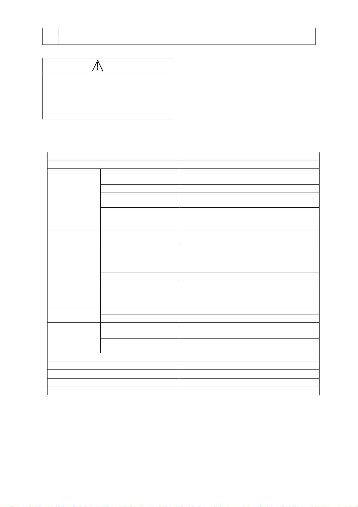
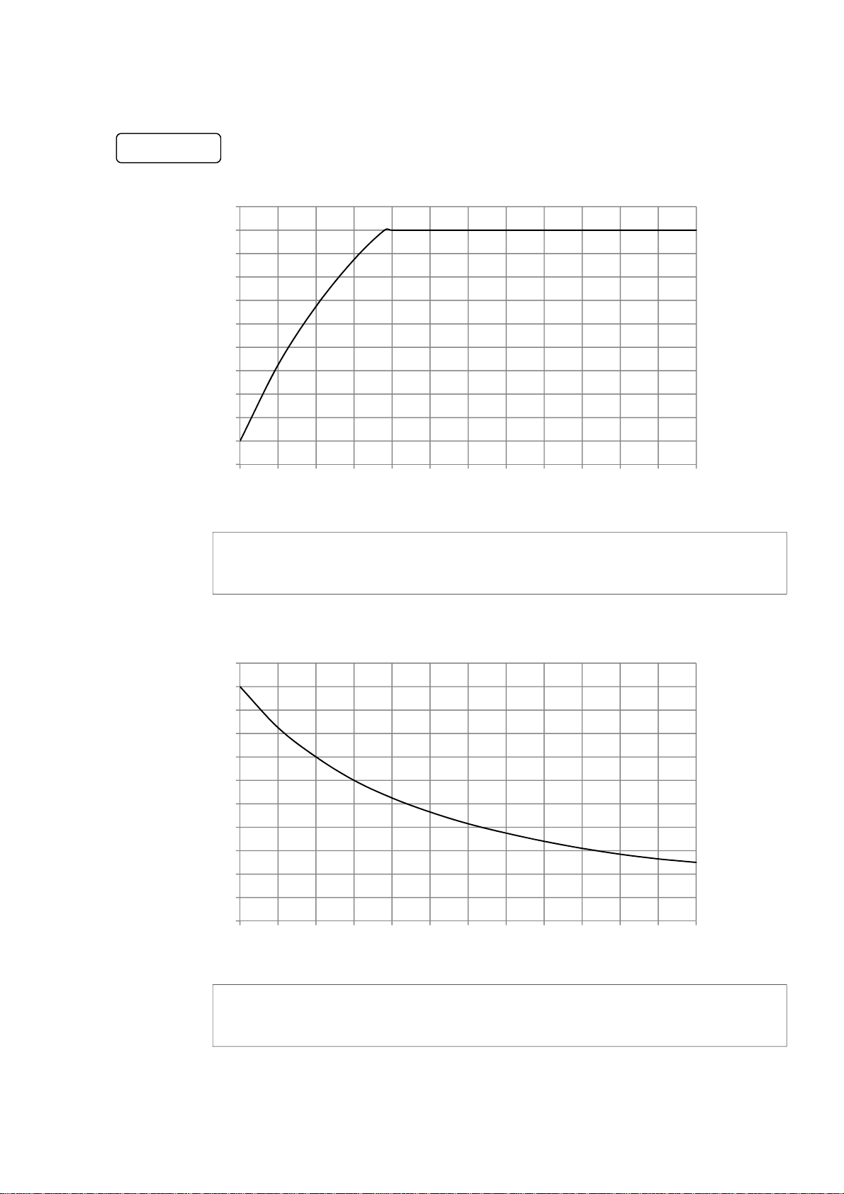
Required time for rising
temperature *1 20→100℃Approx. 15 min.
20→200℃Approx. 40 min.
Range of temperature distribution
*2
5.0℃200℃(When setting up 200℃)
3.0℃(When setting up 120℃)
2.0℃(When setting up 37℃)
Function
Temperature control PIDcontrol with auto-tuning
Setting up temp. • display Sheet key input, digital display
Attached function *3
Auto Stop, Auto Start,
8-step program,
Compensating temperature display, auto tuning, setup for
recovery from power failure, setup for buzzer
Setup time for timer 0 min. to 99 hrs. 59 min.
Safety functions
Self-diagnosis function (
Upper limit temperature limiter, loop abnormality,
Sensor disconnection) Fuse, fixed temperature overheat
prevention device)
Composition Temperature sensor Platinum resistance temperature detectorPt100Ω
Heater Maika heater 235 W
Specification/Standard Block dimensions *4 Model MGBH: 90W x 62.5D x 70H
Model MGB: 90W x 125D x 70H
Number of blocks *4 Model MGBH: 2
Model MGB: 1
Ambient temperature range in use 5 ~ 35℃
Outer dimensions (mm) 200W x 315D x 125H
Mass *5 About3.9kg
Power input 2.5A 250VA
Rated power AC100V 50/60Hz
*1 Room temperature at 20ºC, rated power supply-voltage, regular block model MGB-1524, without
sample/container, without sample temperature sensor.
* 2 Temperature in aluminum block
*3 If sample temperature sensor is used, it may not be controllable under the conditions that the sample thermal
capacity is large, the container thermal conductivity is small, etc.
*4 Aluminum block is one of the optional accessories (sold separately).
As for the types of aluminum block, please refer to “Options” on page 37.
*5 Weight of aluminum block is not included.
-2-
Remodeling and improper use may
cause electric shock or breakdown.

2-3 Temperature rise/drop curve (reference data)
-3-
0
20
40
60
80
100
120
140
160
180
200
220
0 10 20 30 40 50 60 70 80 90 100 110 120
MG-3100
Temperature
(℃)
Time (min)
0
20
40
60
80
100
120
140
160
180
200
220
0 10 20 30 40 50 60 70 80 90 100 110 120
Condition: Room temperature at 20ºC, rated power-supply voltage,
regular block model MGB-1524, without sample/container, without sample temperature sensor.
Time (min)
Condition: Room temperature at 20ºC, rated power-supply voltage,
regular block model MGB-1524, without sample/container, without sample temperature sensor.
Temperature
(℃)

2-4 Names of parts
-4-
Control panel
Power switch
Power cord
Temperature sensor terminal
(With cover)
Sensor holder
Screw for option installation
Fuse holder
Front
Back
Adjuster
Regular block
(Option)
Block handle
Half block
(Option)
Block handle

Constant-value operation Timer mode Step program
②
3-1 Control panel
Names and function of operating parts
3
-5-
③
①
PV display
SV display
Remaining time display
Display of operation types
Auto stop: [1] or [2]
Auto start: S
Key lock
Display
Display of
operation status
Auto start
Display Step
Program display
3-2 Display (Standard screen)
⑦⑤
⑥④
No. Name Function
①Alarm lamp This is lit only when bimetal is in operation.
②Display (LCD) The set temperature, measured temperature, operation status and alarm are displayed.
③Power switch Power is turned ON/OFF.
④RUN/STOP key Temperature control is switched from RUN/STOP.
⑤UP key
Being entered Press it and the value will increase one by one.
Holding it down for more than 1 second will continuously increase the value
and holding it down for more than 10 seconds will even faster increase the value.
Standard
screen
If this is pressed while connected to the sample temperature sensor, it will switch
to the block temperature.
If it is pressed again, it will return to the sample temperature again.
⑥DOWN key
Being entered Press it and the value will decrease one by one.
Holding it down for more than 1 second will continuously decrease the value and
holding it down for more than 10 seconds will even faster decrease the value.
Standard
screen
If the key lock function is set, long press for more than 3 seconds
will switch the key lock function to effective.
Long press for more than 3 seconds will switch it to ineffective.
⑦SET key Switches various settings and confirms set items.
When a certain alarm occurs, the alarm display will be cleared.
Remaining time display
PV display
PV display
SV display
Key lock
Display
Operation status
Display
SV display
Key lock
Display
Operation status
Display
PV 50.0℃
SV 200.0℃
P 25.0℃ 00:01:00
S200.0℃
P 25.0℃ 00:01:00
S200.0℃ S st1/2

-6-
3-3 Constant-value operation, timer mode, step program
This product enables a step program to control the maximum eight set temperatures, including continuous operation in
constant-value operation, auto start and auto stop combining timer mode, in turn.
Constant-value operation
Raises the temperature to the set temperature "T,"
and after the set temperature "T" is reached continuously
operates until operation is stopped.
Timer mode
The use of the timer mode allows operation start
at an optional time or operation
stop at an optional time.
1.Auto start mode
After operation starts, the time count alone starts
and after elapse of a set time "t," the temperature starts
to raise to the set temperature "T" in constant-value operation or
step program.
After the set temperature "T" is reached,
constant-value operation is run and in the case of
the step program, stepwise operation is run.
Temperature
Time
t
T
Temperature
Time
t
T
Temperature
Time
T
Step program Temperature
Time
t1
T2
T1
t2
T3
t3
2. Auto stop mode [STOP 1]
After operation start, the time count starts to raise the
temperature to the temperature “T”set in constant-value
operation and once the temperature "T" is reached, the
constant-value operation starts.
After elapse of the set time “t,”the operation automatically
stops. (Even if the set temperature “T”is not reached, the
operation stops)
Temperature
Time
t
T
STOP1
STOP2
• Range of temperature setting:
• 10.0 - 200.0 ºC (Block control)
10.0 -170.0ºC (Liquid temperature control)
* Range of temperature setting:
10.0 - 200.0 ºC (Block control)
10.0 -170.0ºC (Liquid temperature control)
*Range of time setting: 1 min - 99 hrs. and 59 min
* Range of temperature setting:
10.0 - 200.0 ºC (Block control)
10.0 -170.0ºC (Liquid temperature control)
*Range of time setting: 1 min - 99 hrs. and 59 min
3. Auto stop mode [STOP 2]
After operation start, the temperature raises to the temperature
“T”set in constant-value operation and once the set
temperature “T”is reached, the time count starts.
After elapse of the set time "t," the operation automatically
stops.
Maximum eight-stepped temperature "T" and time "t" are set.
After operation start, the temperature raises to the set
temperature "T" at each step and once the set temperature
"T" is reached, the time count starts.
After elapse of the set time "t," the operation automatically
moves to the next step.
Upon completion of the final step, the operation stops.

3-4 Safety and alarm functions
This product is equipped with the following safety and alarm functions.
If an abnormality occurs, see "6. Causes of trouble and countermeasures" on page 32 and take appropriate
action.
Safety functions
Alarm display
[A-0] Upper temperature limiter
Major cause of
occurrence The measured temperature exceeded the "set temperature + upper
temperature limiter"
* Range of upper temperature limiter set: 0 - 60ºC
Movement Temperature control stops
Alarm display on the display
How to release the
alarm
If returned to the range of measurable temperatures, it can be
released with "Set" key.
Even during alarm, long press of "Set" key enables the set
temperature of the upper temperature limiter to be changed.
[A-3] Loop abnormality alarm
Major cause of
occurrence If the temperature rise for 10 minutes is not more than 1ºC
in the 100% state of temperature control calculation result (heater
output).
Movement [During block control] Temperature control continues and the display
shows the alarm alternately
[During liquid temperature control] Temperature control stops and
the display shows the alarm
How to release the
alarm Released with "Set" key.
[A-4] Blackout recovery alarm
Major cause of
occurrence Power supply stopped once during temperature control and was later
recovered.
Movement
[During STOP set] Temperature control stops and the display shows
the alarm
[During CONT set] The temperature control continues and the display
shows the alarm alternately
*If movement occurs during auto-tuning, the control stops and the
display shows the alarm.
How to release the
alarm Released with "Set" key.
-7-
Safety
mechanism Movement Cause of movement Recovery method
Fuse If overcurrent flows, the fuse is blown
out, shutting down power. Power circuit is short-circuited or
overcurrent flows. See page 35
"7-1 Replacement of fuse"
Fixed
temperature
Overheat
protector
If the heating plate temperature goes
up to about 220ºC, power is shut
down, stopping the control.
The Alarm lamp is lit.
• Excessive overshoot occurred
because PID setting
was not matched or the load
was large
.
• The temperature of the heating
plate goes up to more than about
220ºC as the temperature
controller went out of order.
Check that the heating plate
temperature goes down, and turn
on the power again.
If this frequently occurs,
immediately stop operation and
contact the company from which
you purchased the product or the
nearby service center.
Temperature
controller
Self-diagnostic
function
(Upper
temperature
limiter))
When the heating plate temperature
exceeds the set temperature of the
upper temperature limiter, all controls
stop.
Alarm is displayed.
Excessive overshoot occurred
because PID setting was not
matched or the load was large.
See page 14
"5-4-1 Upper temperature limiter"
PV 270℃
SV A-0
PV 25℃
SV A-3
PV 25℃
SV A-4

[A-25] Auto-tuning error (Block control)
Major cause of
occurrence
During auto-tuning by the internal temperature sensor, it occurs in
any one of the following conditions:
• If deviated from the measurement range
• If the heater is off for more than 3 hours
Movement Auto-tuning stop
Alarm display on the display
How to release the
alarm Released with "Set" key.
[A-26] Auto-tuning error (Liquid temperature control)
Major cause of
occurrence
During auto-tuning by the sample temperature sensor, it occurs in
any one of the following conditions:
• If deviated from the measurement range
• If the heater is off for more than 3 hours
Movement Auto-tuning stop
Alarm display on the display
How to release the
alarm Released with "Set" key.
[F-99] Memory alarm
Major cause of
occurrence This occurs when the set value memorized by the control substrate
is abnormal
Movement Temperature control stops
Alarm display on the display
How to release the
alarm Stop the operation and contact the company from which you
purchased the product or the nearby service center.
[F-97] AD alarm
Major cause of
occurrence This occurs when an abnormality occurs in the temperature input
circuit
Movement Temperature control stops
Alarm display on the display
How to release the
alarm
Auto recovery.
If the alarm is not released, stop the operation and contact the
company from which you purchased the product or the nearby
service center.
[HHHH][F-1] Measured temperature upper limit alarm
Major cause of
occurrence
(i) The temperature exceeds the measurable temperature of the
temperature sensor.
* Range of measurable temperatures: -50~-350ºC
(ii) The sample temperature sensor is disconnected or the connector
comes off.
Movement Temperature control stops
Alarm display on the display
How to release the
alarm
(i) If recovered to the measurable range, the alarm can be released
with "Set" key.
If the displayed temperature is clearly away from the actual
temperature, stop the operation and contact the company from
which you purchased the product or the nearby service center.
(ii) After turning off the power switch, reconnect the sample
temperature sensor.
[LLLL][F-1] Measured temperature lower limit alarm
Major cause of
occurrence The temperature goes below the measurable range of the
temperature sensor.
* Range of measurable temperature: -50 to 350℃
Movement Temperature control stops
Alarm display on the display
How to release the
alarm
If returned to the range of measurable temperatures, it can be
released with "Set" key.
If the displayed temperature is clearly away from the actual
temperature, stop the operation and contact the company from
which you purchased the product or the nearby service center
-8-
PV 25℃
SV A-25
PV 25℃
SV A-26
PV ---℃
SV F-99
PV ---℃
SV F-97
PV HHHH℃
SV F-1
PV LLLL℃
SV F-1

When installing the product, select the following place
and install it.
4-2 Installation conditions
Do not install the product in a place with
a hazardous atmosphere
This product is not explosion proof
specification. Use in a hazardous atmosphere
may cause fire.
Warning
Precautions for the installation environment
A poor installation environment may
accelerate damage to the product
or fail to fully demonstrate its performance.
Caution
Do not put any inflammables near the
installed place.
This product is subject to very high
temperatures. Inflammable in the vicinity may
cause fire.
Caution
Be careful about the handling of
aluminum blocks
When carrying about aluminum blocks, firmly
hold the handle.
If you drop a block on your hand or foot, you
may get injured.
Caution
Installation
4-1 Installation environment
4
When handling a deleterious or poisonous
solvent, use it in a drought chamber.
When handling a deleterious or poisonous
solvent or a similar solvent, wrong handling may
lead to unexpected accidents.
Furthermore, please obtain the material safety
data sheet (SDS) from the company from which
you purchased the product for your safety use.
Be sure to secure space as shown in the
figure away from the wall surface,
ceiling surface, etc.
Secure space around the device
Caution
Warning
20cm
⁕Free of flammable solid, liquid or gas in the surrounding.
⁕With out exposure to direct sunshine.
⁕The ambient temperature is between 5 and 35ºC.
⁕Well ventilated. Or can be fully ventilated.
⁕Not condensing.
⁕Has a little humidity and does not have water droplet.
⁕Has a little dust.
⁕Horizontal, stable and robust.
(Check the weight in operation of the product)
-9-
20cm
20cm
(Excluding the heating unit which is an option)

4-3 Connecting utilities
Check the voltage, phase and
capacity of power and correctly
connect it
Wrong connection of power source
may cause fire or electric shock accidents.
Do not use branched
output or table tap
It may cause
cable burning or fire from overcurrent.
Warning
Warning
* When connecting to the power source, do not
use branched outlet or table tap.
* Check that the covering of the power cord is not
damaged.
There is a fear of electric shock.
(1) Check the voltage, phase and capacity of power
source to connect to the product model.
Power source to which the product connects is as
follows.
* Do not connect the power plug to the outlet, yet.
(2) Check the outlet at the installation place.
Prepare an outlet with grounding.
Specification of power cord
Cable
Power plug Section area of
electric wire
(AWG)
Length Thickness
(outer
diameter)
About
2 m About 7 mm 3 poles with
grounding 0.75 mm2
(AWG18)
Product model
Power source necessary
for connection
Voltage Capacity
MG-3100 AC100V 15A
Never connect ground wires to the gas or
water pipe to prevent electric shock accidents.
Correctly connect ground wires
Warning
-10-

Heating plate
5-1 Preparation for operation
Operation
5
Use only designated aluminum
blocks.
Use of an aluminum block other than those
designated may worsen temperature control
or temperature distribution and may cause
unexpected accidents.
Caution
-11-
Pay attention to the number of
aluminum blocks
Be sure to set the maximum number of
aluminum blocks for each device before
operation. It may cause degradation of and
temperature distribution or abnormal heat of
the heater.
Caution
* If you use a container other than glass, please check
the temperature limit before use.
Depending on the temperature in use, the container may
dissolve.
* When changing aluminum blocks, do not place high
temperature aluminum block on the top surface of the
device. The device may go out of order.
(2) Check that the heating plate and bottom surface of
aluminum blocks are free of deformation or attachment of
trash, stains, etc.
* Deformation of the heating plate or attachment of trash,
stains, etc. may worsen temperature precision or
temperature distribution.
(3) Gently place the required number of blocks.
The block handle of a regular block should be placed
inside the block.
The block handle of a half block should be caracoled
and placed on the top surface of the device.
(4) Check that the power switch is OFF and insert the
power plug into the outlet.
Be careful about the temperature
when replacing aluminum blocks
Check that the aluminum blocks and block
handle are cooled down before working on
them. Touch at high temperatures may lead to
burn.
Caution
(1) Prepare aluminum blocks suitable for the container to
be used.
See the right table for the types and required number of
aluminum blocks.
See "Option" on page 37 for types of blocks.
Half block Regular block
Model MGBH: 2 Model MGB: 1
Be fully careful about the use of
inflammable and flammable solutions
An inflammable, flammable solution (methanol
etc.) turns into gas if allowed to stand at more
than the room temperature (or below it
depending on a solution), potentially leading to
catching fire or burning with a certain source of
ignition.
For use, be sure to ventilate the room
and exercise full cautions.
Caution
A liquid spilt over the heating
plate or top surface of the device
should be wiped off promptly.
Water or a solution spilt over the top surface
of the device or the heating plate should be
wiped off promptly.
If it is left to stand, the heating plate may get
corroded or infiltration into the device may
lead to an accident such as electric leakage.
Caution
Top surface of the device
Half block
Regular block
Block handle
Block handle

5-2 Start/stop of temperature control
-12-
3) Stop temperature control
Press "Run/Stop" key.
"ºC" in PV column switches to lighting,
stopping temperature control.
Set Run
Stop
Set Run
Stop
Set Run
Stop
Set Run
Stop
During
temperature
rise
During
temperatur
e control
Set Run
Stop
During suspension of temperature control
(The situation that the
liquid temperature
exceed the set
temperature)
When you terminate operation,
stop temperature control before turning OFF the power
switch. If you do not use the device for a long time, unplug
from the outlet.
Processing
after operation
2) Start temperature control
Press "Run/Stop" key.
"ºC" in PV column switches to blinking,
starting temperature control.
* The blinking display is not interlocked with energization of the heater.
During temperature rise, " " is displayed. " " is displayed during
temperature control.
This starts/stops temperature control.
Do not touch
the aluminum blocks and block
handle during and after use
If the set temperature is high, the aluminum
blocks and block handle are at high temperatures during and
after use.
If you touch any of them, you may get burned. Be careful.
Caution
1) Turn on the power switch.
The mode and version are displayed and then the standard screen appears.
* Setting method is common to block control and liquid temperature control.
• Block control: Control temperature of aluminum blocks
• Liquid temperature control: Control liquid temperature with a sample temperature sensor, which is an option
Standard screen
3
2
Do not heat with a container sealed
If you close the cover and heat to high temperatures in
an airtight state,
the pressure inside the container increases and the
container may get broken.
Check the set temperature and the state of the solution
and cover before starting operation.
Caution
PV 25.0℃
SV 200.0℃
PV 200.0℃
SV 200.0℃
PV 50.0℃
SV 200.0℃
PV 200.0℃
SV 200.0℃
PV 180.0℃
SV 150.0℃

5-3 Temperature setting
-13-
* Setting method is common to block control and liquid temperature control.
• Block control: Control temperature of aluminum blocks
• Liquid temperature control: Control liquid temperature with a sample temperature sensor, which
is an option
* The temperature set can be changed during temperature control or stop of temperature control.
2) SV (set temperature) switches to blinking, enabling
temperature to be set.
3) Press "▲" or "▼" to enter the set temperature:
if you continue pressing it, the value continuously changes.
Range of setting
• Block control: 10.0 to 200.0ºC (Default 10.0ºC)
• Liquid temperature control:10.0 to 170.0ºC
4) Press "Set" key to confirm.
Set
5) SV (set temperature) switches to the normal display.
Run
Stop
Set Run
Stop
Set Run
Stop
Set Run
Stop
3
4
1) Press "Set" key on the standard screen.
3
Set the temperature you want to control.
Pay attention to the set temperature
Setting temperature beyond the ignition point of the
solution may result in burning.
Check the solution to be used and the set temperature.
Caution
PV 25.0℃
SV 10.0℃
PV 25.0℃
SV 10.0℃
PV 25.0℃
SV 200.0℃
PV 25.0℃
SV 200.0℃

5-4 Setting mode
-14-
5-4-1 Upper temperature limiter
Set Run
Stop
Set Run
Stop
Set Run
Stop
3)Press "▲" or "▼" key and enter the set value.
if you continue pressing it, the value continuously changes.
Range of setting: 0-60ºC (Default 5ºC)
4) Press "Set" key to confirm.
Set Run
Stop
5) Long press "Set" key.
It returns to the initial standard screen.
3
4
1) Long press "Set" key on the standard screen.
3
Long press
Long press
If the set temperature exceeds "Set temperature + Upper temperature limiter," the alarm is displayed,
stopping temperature control.
* The set temperature is changed but the set value of the upper temperature limiter remain
unchanged (See the figure below)
* The device operates as the device protection even beyond 210ºC.
* Both block control and liquid temperature control are effective.
Change the set
temperature
Set temperature
Operating temperature of upper
temperature limiter
Upper temperature limiter (5ºC)
50ºC
55ºC Set temperature
Operating temperature of device
protection
Upper temperature limiter (5ºC)
Operating temperature of upper
temperature limiter
100ºC
105ºC
210ºC
2) Press "▼" or "▲" key, check that "OVER TEMP" is blinking and
press "Set" key.
If the set temperature is 50ºC If the set temperature is 100ºC
PV 25.0℃
SV 200.0℃
SETTING SELECT
OVER TEMP
SETTING SELECT
OVER TEMP
OVER TEMP
5℃

5-4-2 Timer mode, step program
-15-
Set Run
Stop
Set Run
Stop
SETTING SELECT
MODE SELECT
Long press
1) Long press "Set" key on the standard screen.
2) Check that "MODE SELECT" is blinking and press "Set" key.
Set screen of each mode is displayed in the following order.
Functions of auto start, auto stop and step program can be set.
Step program can be set up to 8 steps.
AUTO START
OFF
Press "Set" key while the auto start is invalid "OFF" and the
screen moves to the setting screen in (8) Auto stop.
Set Run
Stop
AUTO START
ON
Set Run
Stop
AUTO START
ON 00:01
4
5
6
4
67
6) Press "▲" or "▼" key to enter the time to operation start.
Range of setting: 1 min to 99 hrs. and 59 min (Default 1 min)
7) Press "Set" key to confirm.
It moves to the setting screen for Auto stop.
AUTO START
MODE SELECT
AUTO STOP
STEP
Press Set key
Press Set key
Press Set key
4) To turn "ON" the Auto start, press "▲" or "▼" key.
The blinking display switches "ON"←→"OFF."
* Even if you change it to OFF, the condition you set once will
not be erased.
5) Press "Set" key to confirm.
Set Run
Stop
3) The setting screen for AUTO START is
displayed.
Press Set key
PV 25.0℃
SV 200.0℃
Table of contents
Other EYELA Laboratory Equipment manuals
Popular Laboratory Equipment manuals by other brands

Malvern
Malvern Nano Series Basic guide

MO BIO Laboratories
MO BIO Laboratories PowerWater DNA instruction manual

Buchi
Buchi Rotavapor R-300 Operation manual

Biotage
Biotage Extrahera HV-5000 Installation checklist

ORiNG
ORiNG INJ-101GT++ Series Quick installation guide

Thermo Scientific
Thermo Scientific Ion Trap Series Hardware manual