5
6.0 Before Installing the Units
Inspect the filters for any material or structural damage prior to use
and replace any damaged filters before operating the unit.
An optional (not included with unit) round exhaust collar is available
that accepts 8" diameter rigid or flexible ducting and fits over both the
corner and rear exhaust outlet grills of the HFS800C. The collar slides
in over the exhaust outlet grills and is secured by offset tabs and
machine screws.
As with any air filtration system, airflow losses not attributable to
the HEPA Filtration System will reduce the airflow of the system. The
following recommendations can facilitate user installation and
minimize airflow losses created by external static resistance.
1. Always use the minimum length of ducting possible with the
fewest possible number of turns and bends.
2. Rigid metal ducting creates less turbulence and consequently less
airflow loss than flexible ducting. Regardless of the type of ducting
used, rigid “sweep-type”, radiused connections should be used for
all turns and bends.
3. If flexible ducting is used, it must be kept as taut as possible to
avoid “pancaking” or flattening.
4. Louvers, dampers, and other external control devices should be
sized to provide the equivalent open area to the cross sectional
area of the exhaust duct.
5. When utilizing the HFS800C for negative pressure applications,
airflow and air changes per hour are maximized by utilizing both
the corner and rear exhaust outlets.
6. For negative pressure applications, the total volume of air supplied
to the room must be lower than the volume of air exhausted by the
air filtration unit. The minimum recommended differential is the
greater of 100 CFM or 10%. Negative pressure levels should be
continuously monitored.
NOTE: If the air supply to the room is not controlled, sufficient
negative pressure might not be achieved.
7.0 Location and Modes of Operation
The HFS800C unit can be used in various modes of operation. The
unit is designed to be suspended in a standard 2 foot x 4 foot drop
ceiling grid. Refer to Figure C
The modes of operation are as follows:
1. Negative pressure - all of the filtered air is exhausted to an external
environment, or re-circulated within the facility if allowed by federal,
state, local, and facility ventilation codes. The other exhaust outlet
can be sealed with the solid cover plate or used as a second
exhaust outlet.
2. Negative pressure and recirculation - approximately 50% of the
filtered air is exhausted through one outlet and the other 50% is
re-circulated back into the room through the other outlet.
3. Full in room recirculation - all of the filtered air is re-circulated back
into the room through both exhaust outlets.
8.0 Installation
NOTE: Access above the ceiling is required for installation
and servicing.
NOTE: This ceiling-mounted unit is not recommended for contact with
insulation materials. Make sure there is at least 6" of air space around
the entire outside surface of the unit.
NOTE: Installation must be performed by qualified maintenance
personnel only. All wiring must be done by a qualified and licensed
electrician in accordance with local, NEC, and CEC electrical codes.
WARNING: Risk of electrical shock! Can cause serious injury or
death! Make sure the unit is turned “OFF” and disconnected from
power supply during the wiring and installation process. Read and
follow all warnings and cautions in the “Electrical and Safety
Requirements” section of this instruction manual before wiring
and installing unit.
WARNING: Risk of electrical shock! Can cause serious injury or
death! Turn the electrical power switches and circuit breakers for
the HVAC system “OFF” before connecting the unit to any part of
the HVAC system, including air ducts. Check to ensure that the unit
is turned “OFF” and disconnected from electrical power source while
being connected to HVAC system.
CAUTION: When installing the unit, always wear the proper personal
protective equipment (particularly eye and hand protection) and follow
safe work practices in accordance with federal, state, local, provincial
and employer regulations. Be extremely careful when handling sheet
metal during installation because serious injury could result from
coming in contact with sharp edges.
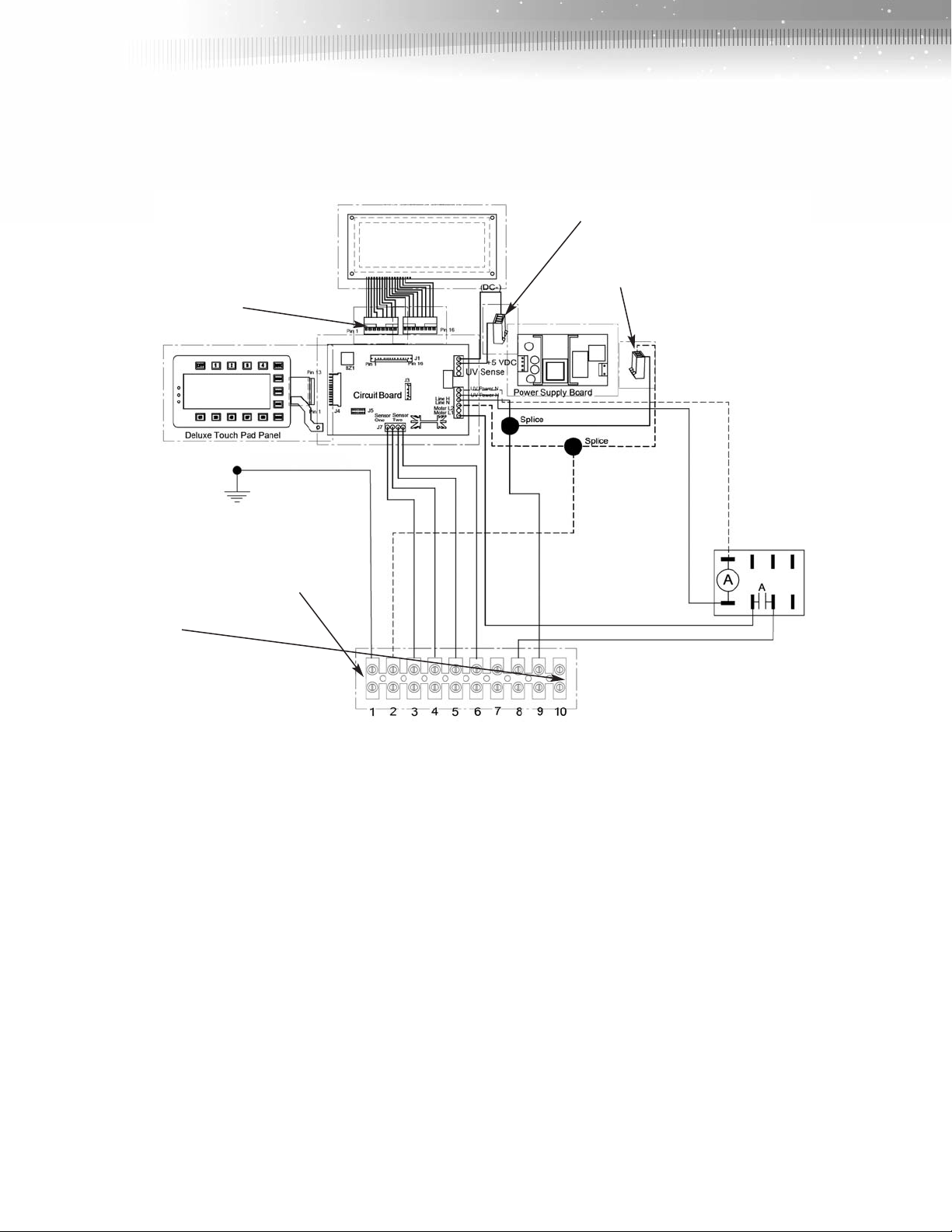
Refer to Figure C, and the various wiring diagrams and
schematics in this instruction manual before hard-wiring or
installing the HFS800C.
As stated previously; the HFS800C ceiling mounted unit fits in a 2 foot
x 4 foot drop ceiling grid.
1. Remove the rear panel of the unit (held in place with Phillips head
screws) to gain access to the unit’s electrical wiring and terminal
block. The terminal block is located inside the cabinet, adjacent to
the knockouts.
2. The unit must be hard-wired to its control panel box and to the
building electrical system. Knockouts are provided in the unit’s
cabinet for access to the wiring and terminal block. As a minimum
requirement, 14 gauge wiring should be used to connect the unit to
the facility’s electrical system.
NOTE: Carefully read the various wiring diagrams and schematics
in this instruction manual.