BIOMET VANGUARD XP User manual
Surgical Technique

Over 1 million times per year, Biomet helps one surgeon
provide personalized care to one patient.
The science and art of medical care is to provide the right
solution for each individual patient. This requires clinical
mastery, a human connection between the surgeon and the
patient, and the right tools for each situation.
At Biomet, we strive to view our work through the eyes of one
surgeon and one patient. We treat every solution we provide
as if it’s meant for a family member.
Our approach to innovation creates real solutions that assist
each surgeon in the delivery of durable personalized care
to each patient, whether that solution requires a minimally-
invasive surgical technique, advanced biomaterials, or a
patient-matched implant.
When one surgeon connects with one patient to provide
personalized care, the promise of medicine is fulfilled.
One Surgeon. One Patient.

Surgical Technique Summary.............................................................................................................................................................................. 2
Overview......................................................................................................................................................................................................................... 6
Preoperative Planning............................................................................................................................................................................................. 6
Incision............................................................................................................................................................................... 6
Patella Preparation ................................................................................................................................................................................................... 7
Patella Resection ...................................................................................................................... 7
Femoral Preparation...............................................................................................................................................................................................10
Distal Femoral Resection....................................................................................................... 10
Femoral Sizing............................................................................................................................13
4-in-1 Femoral Cuts ..................................................................................................................14
Tibial Preparation ....................................................................................................................................................................................................15
Tibial Resection with Intact/Functional ACL...................................................................15
Tibial Resection without Intact/Functional ACL........................................................... 26
Stem Preparation without the ACL.................................................................................... 27
Trial Reduction...........................................................................................................................................................................................................28
Implant Reduction...................................................................................................................................................................................................30
Tibial Tray Implantation with Intact/Functioning ACL............................................... 30
Tibial Tray Implantation without Intact/Functioning ACL........................................ 32
Femoral Component Implantation.................................................................................... 33
Patellar Component Implantation ..................................................................................... 34
Tibial Bearings and Locking Bar Implantations ............................................................ 34
VANGUARD XPTotal Knee System
Table of Contents
Biomet does not practice medicine. The treating surgeon is responsible for determining the appropriate treatment,
technique(s), and product(s) for each individual patient. This technique was prepared in conjunction with the
Vanguard XP Total Knee developing surgeons; and the “eXPert Advice” sections provided in this surgical technique
represent the Vanguard XP developing surgeons’ recommended approach.
This material is intended for health care professionals and the Biomet sales force. Distribution to any other recipient
is prohibited. All content herein is protected by copyright, trademarks and other intellectual property rights owned
by or licensed to Biomet Inc. or its affiliates unless otherwise indicated, and must not be redistributed, duplicated
or disclosed, in whole or in part, without the express written consent of Biomet.
1
4
7
2
5
8
3
6
9
2
VANGUARD XPTotal Knee System
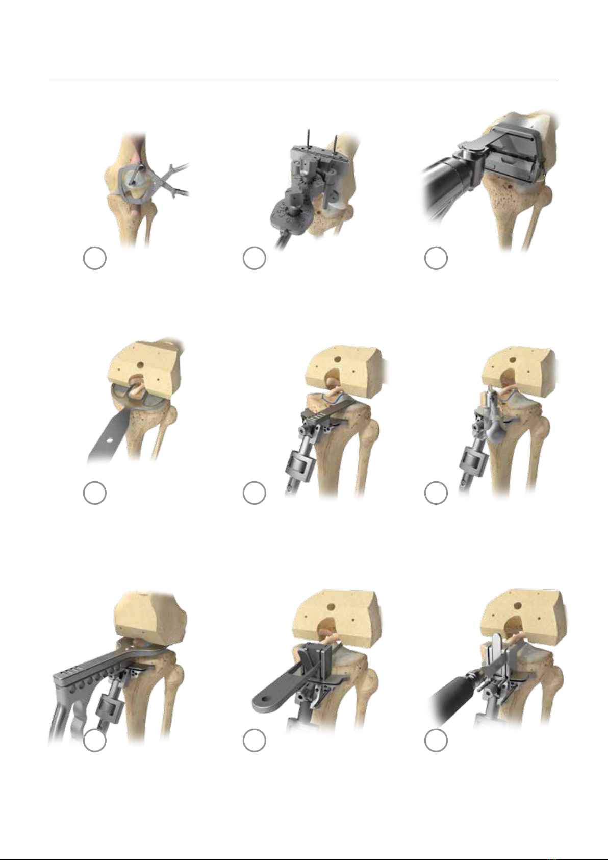
Surgical Technique Summary
Femoral Preparation: 4-in-1 cuts
Initial Island Alignment
Tibial Resection Depth Tibial Island Alignment
Tibial ResectionTibial Posterior Slope
Tibial Vertical Resection
Patella Preparation Femoral Preparation

10
13
16
11
14
17
12
15
18
3
Anterior Rongeur
Tibial Slope Gauge Flexion/Extension Gap Check Tibial Sizing and Floating Tibial Trial
Tibial Preparation Final Trialing Component Implantation
Tibial Horizontal Resection Tibial Medial Gap Check

Overview
Intact ACL and PCL Intact, Functioning PCL Partially or Non-functional PCL
Femoral Component XP Femur XP Femur XP Femur
Tibial Component XP Tibia XP or CR Tibia XP or CR Tibia
Bearing XP- XP Bearings XP - XP Bearings XP - AS Bearings
If additional implant constraint is desired, the Vanguard PS or PSC system can be utilized.
4
VANGUARD XPTotal Knee System
The Vanguard XP Total Knee System consists of:
• An ACL/PCL retaining femoral component
• Two tibial trays: XP and CR
• Two bearing designs: XP-XP and XP-AS
The components can be used in dierent combinations, depending on the patient’s soft tissue status (see table below).
Note:
• FemoralPegs:TheVanguardXPfemoralcomponenthastwomodulardistalpegs.Tohelpaddressminor
bone deficiencies, the pegs can be removed and distal femoral augments attached using an augment
bolt or an augment peg.
• Femoral Augments: The use of femoral augments does not necessarily change the recommended
implant combinations (table above) – the appropriate implant combination should be chosen based on
the intact soft tissues.
Description
Biomet manufactures a variety of knee joint replacement prostheses intended for application with or without bone
cement. Knee joint replacement components include femoral, tibial, and patellar components. Components are available
in a variety of designs and size ranges intended for both primary and revision applications. Specialty components are
available including femoral stems, femoral screws, femoral augments, tibial stems, tibial screws, tibial augments, tibial
cement plugs and modular pegs.
• The Vanguard XP Knee System oers the exibility to change from an ACL/PCL retaining (XP) to a PCL retaining (CR),
or non-functional PCL (AS) within a single system.
• Thetransitionbetweeneachconstraintlevelcanbemadewithease,allowingthephysiciantoevaluatesofttissueand
bone deficiencies intraoperatively without making a preoperative commitment to the level of constraint.
• The Vanguard XP femoral components (PN 195905-195952) may also be used with the Vanguard standard line
(i.e., CR, CR-L and AS bearings) E1 Polyethylene and UHMWPE (Arcom) bearing components (when used
with Vanguard tibial trays).
Note: Improper surgical technique may result in damaging/impinging the ACL, undercutting/over-cutting/
over-cutting/fracture of the tibial bone island, and/or difficulty in component fit/sizing with patient
anatomy soft tissues.

The Vanguard XP Total Knee System,
supporting instrumentation platform, and surgical
technique have been designed in collaboration
with the Vanguard XP Development Team:
Prof. Tom Andriacchi
Dr. Keith Berend
Dr. Jerey DeClaire
Dr. Craig Della Valle
Dr. Jorge Galante
Dr. Adolph Lombardi
Dr. Chris Peters
5
INDICATIONS
1. Painful and disabled knee joint resulting from
osteoarthritis,rheumatoidarthritisor traumatic arthritis
where one or more compartments are involved.
2. Correction of varus, valgus, or post-traumatic
deformity.
3. Correction or revision of unsuccessful osteotomy,
arthrodesis, or failure of previous joint replacement
procedure.
Femoral components and tibial tray components
with porous coatings are indicated for cemented and
uncemented biological fixation application. Non-
coated (Interlok) femoral components, tibial tray
components and all polyethylene patellar components
are indicated for cemented application only. Regenerex
components (where available) are intended only for
uncemented, biologic fixation application.
CONTRAINDICATIONS
Absolute contraindications include: infection, sepsis, and
osteomyelitis. Relative contraindications include:
1) an uncooperative patient or a patient with neurologic
disorders who is incapable of following directions, 2)
osteoporosis, 3) metabolic disorders which may impair
bone formation, 4) osteomalacia, 5) distant foci of
infections which may spread to the implant site, 6) rapid
joint destruction, marked bone loss or bone resorption
apparent on roent genogram, 7) vascular insufficiency,
muscular atrophy, neuromuscular disease, and/or
8) incomplete or deficient soft tissue surrounding the
knee.
For complete product information, including warnings, precautions, and potential adverse effects,
see the package insert and www.Biomet.com (where available). Check for country product clearances
and reference product specific instructions for use.
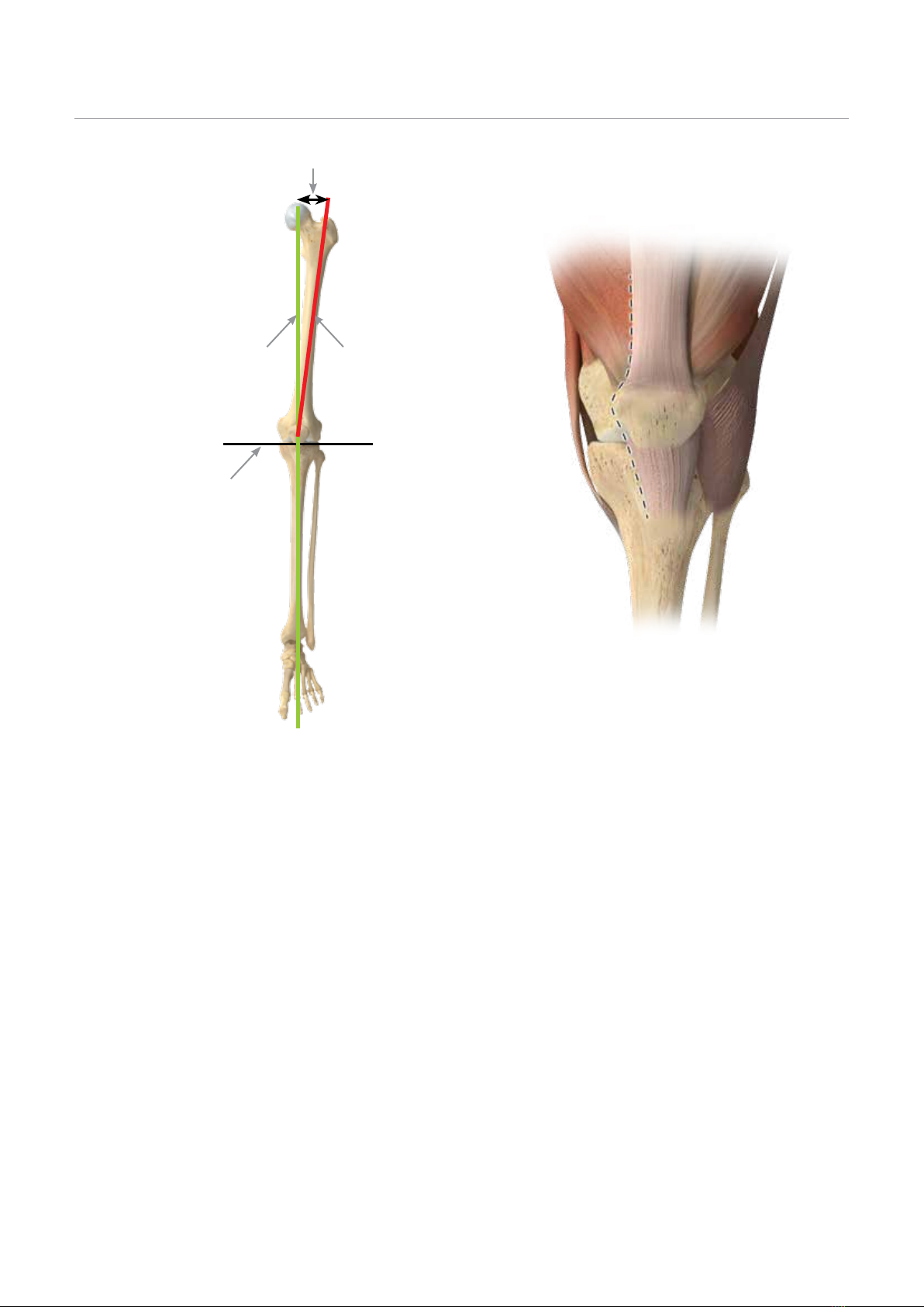
Figure 1
Figure 2
Perpendicular Resection
Mechanical Axis Anatomic
Valgus Angle
6
VANGUARD XPTotal Knee System
Preoperative Planning
• Assess bone stock and potential ligament instability and
the anatomical axis with 36" long standing A/P X-rays.
• Measure valgus angle (angle between anatomic and
mechanical axis) to assure the distal femoral cut is
perpendicular to the mechanical axis (Figure 1).
• Estimate femoral component size using lateral
view X-ray.
Note: Confirmation of the appropriate size component
intraoperatively is critical for normal kinematics.
Incision
• The Vanguard XP Total Knee Instrumentation is
designed for a standard surgical technique (Figure 2).
• Release the patella tendon to create space on the
lateral side of the tibia. Ensure that the patella tendon
tibia interface is released so the patella can easily sit in
the lateral gutter of the knee.
Note: If multiple scars from previous surgeries exist,
evaluate skin incision placement and elements of
scarring which may decrease soft tissue mobility.
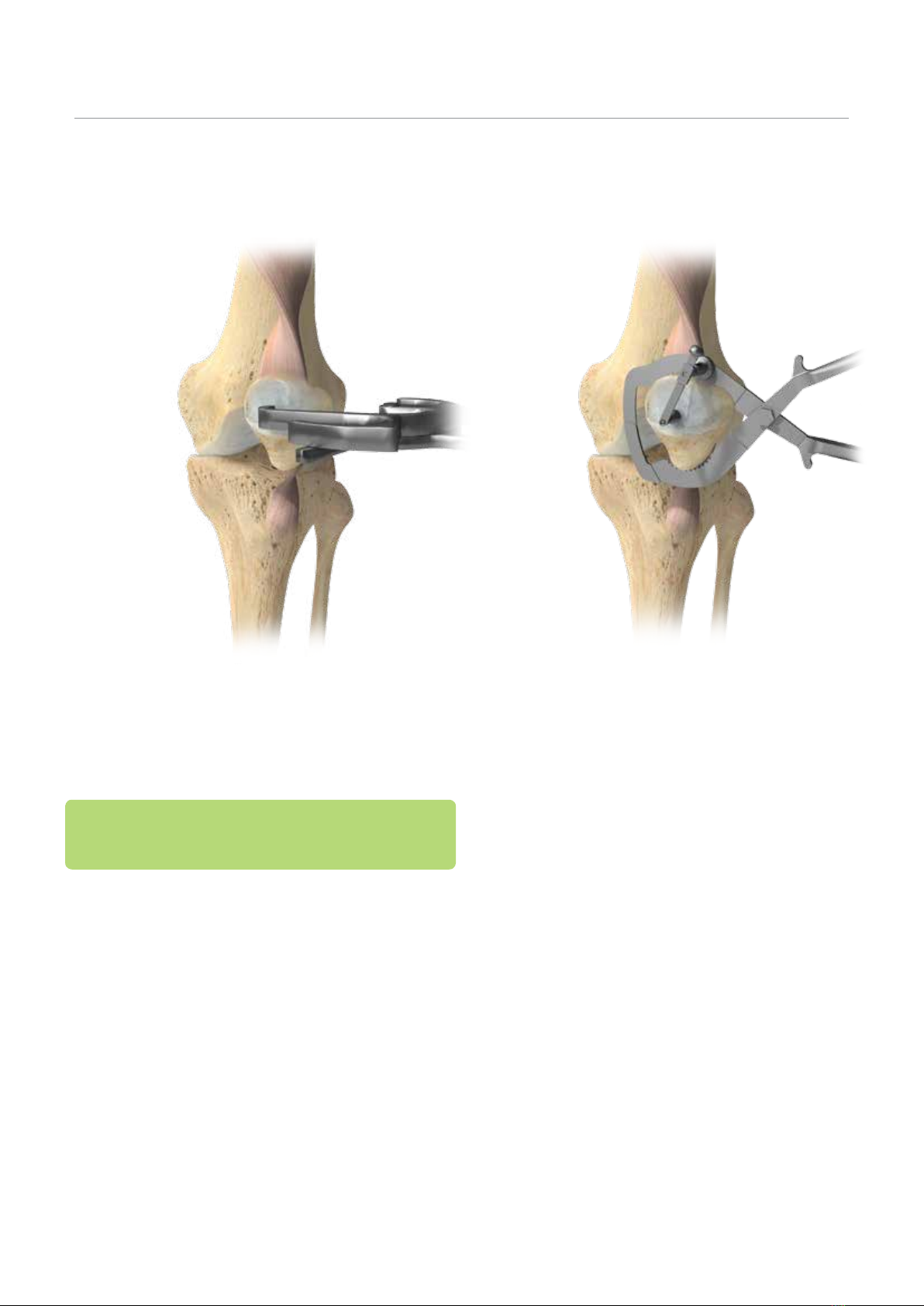
Figure 3 Figure 4
7
Patella Preparation
Patella Resection
eXPert Advice: Preparation of the patella at this time
frees up the joint capsule and facilitates exposure for the
remainder of the case.
Option 1: Surface Clamp
• Tilt the patella for patella preparation.
• Remove the osteophytes and peripatellar tissues
down to the level of the quadriceps and patellar
tendon insertion.
• Determine the patella thickness and resection amount
by using the patella caliper (32-486502) (Figure 3).
- The patella saw guide stylus (32-486501) can be
utilizedtodeterminetheappropriateresectionlevel
(Figure 4).
• Use the patella clamp surface cut guide to perform the
initial, at patellar resection.
Note: Care should be taken to restore original patella
thickness to prevent overstung or under tensioning of the
patella-femoral joint.
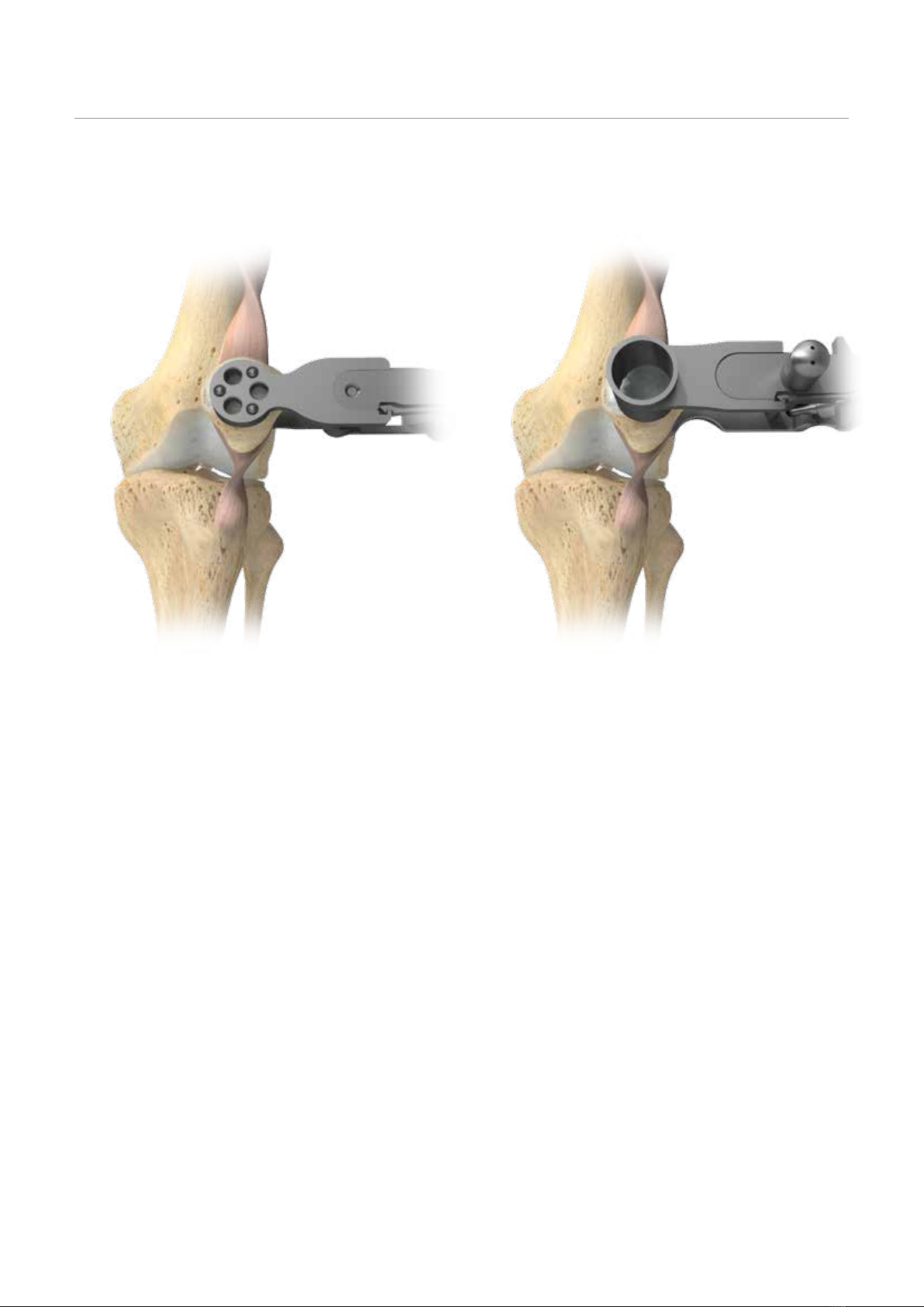
Figure 6
Figure 5
8
VANGUARD XPTotal Knee System
Patella Preparation
Patella Resection (cont.)
• Single peg patellar component
- Use the single peg patellar drill guide
(32-486520–32-486525) to locate the placement of
the central peg.
- Drillthe central hole using the 5/16"Series A patellar
drill (32-347021 or 32-347022).
- Select a trial patellar component to optimize
coverage without increasing patellar thickness
beyond pre-resection height.
• 3-peg patellar component
- Place the appropriately sized 3-peg drill guide
(32-486530–32-486535) onto the resected patella
and use the 1/4" patellar drill (32-468470) to prepare
for the component pegs (Figure 5).
Option 2: Patella Milling
• Tilt the patella for patella preparation.
• Remove the osteophytes and peripatellar tissues down
to the level of the quadriceps and patellar tendon
insertion.
• Determine the patella thickness and resection amount
by using the patella calliper (32-486502).
• Size the patella using the mill bushings (32-486830–
32-486835) (Figure 6).
• Attach the size-specic bushing to the mill handle
(32-486800).

Patella Preparation
Figure 7
9
Patella Resection (cont.)
Note: The patella size and thickness will determine if a
standard or thin patella should be used.
• Firmly clamp the patella with the mill handle paying
careful attention not to tilt the patella.
• Attach the appropriate size-specic patella reamer
(3 peg, 32-480158–32-4801640) or single peg,
(32-480151–32-480156) to the reamer shaft (32-486802
(Figure 7).
• Attach the proximal shaft to a power drill.
• Insert the reamer basket into the mill bushing and
allow the reamer’s central bit to rest on the apex of the
patella bone.
• Attach the appropriate thickness magnetic spacer
(marked, “Bit”) to the adjustable depth stop.
• Set the adjustable stop by depressing the button on its
side and slide the stop down until the bottom of the
spacer touches the mill bushing.
Note: The magnetic spacer bit includes the depth of
the peg. Do not sink the drill bit prior to setting the
adjustable stop.
• Remove the magnetic spacer and ream until the
adjustable stop touches the mill bushing.
• Remove the reamer assembly and then disengage
the mill handle by pulling the thumb trigger towards
the handle.
• 3-peg patellar component
- Prepare the inset surface using the appropriate
sized surface reamer.
- Establish the resection depth using the magnetic
spacer marked with a red dot.
- The 3-peg drill guide is tapped into the prepared
patella inset and the 1/4" patellar drill is used to
make the holes for the component pegs.

Figure 8 Figure 9
B
A
10
VANGUARD XPTotal Knee System
Distal Femoral Resection
eXPert Advice: It is strongly recommended to utilize a femur
rst technique to facilitate exposure and preparation of
the tibia.
• Utilize the .375" intramedullary (IM) drill (32-485025) to
penetrate the intercondylar notch of the distal femur to
a depth of approximately 1.5–2" (3.5–5 cm) (Figure 8).
• Place the canal entry location 1 cm above the insertion
of the posterior cruciate ligament and slightly medial in
the intercondylar notch.
Note: Irrigation and suction of the femoral canal can be
performed to decrease canal contents.
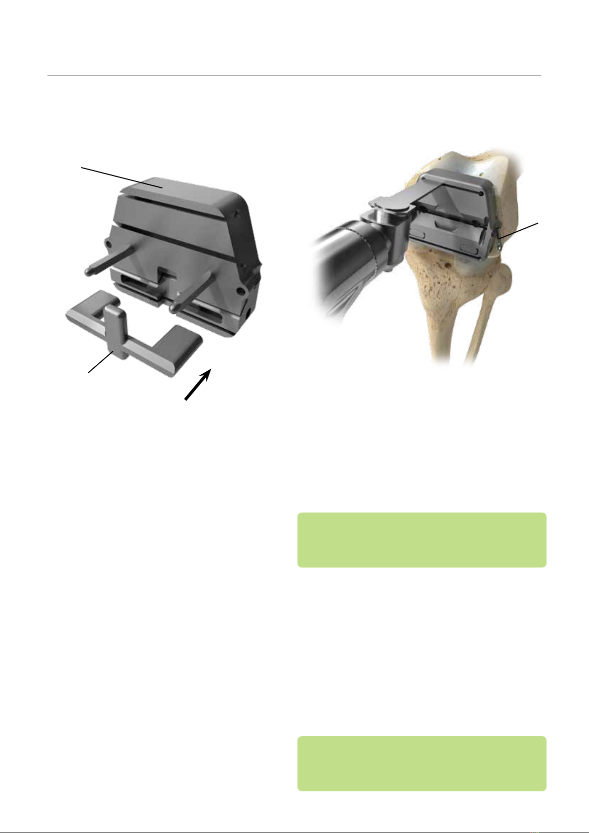
Option 1: Adjustable Distal Femoral
Resection Guide
• Set the adjustable distal cut guide (32-487000) to
the desired valgus angle by pressing and turning the
valgus angle dial (Figure 9A).
• Select the depth of distal resection by turning the
resection level dial (Figure 9B).
Femoral Preparation
1 mm
9
0
11 mm
9
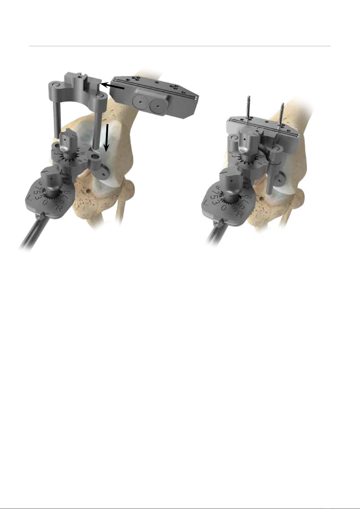
Figure 10 Figure 11
11
Femoral Preparation
Distal Femoral Resection (cont.)
• Assemble the IM rod (32-485030) and adjustable distal
cut guide (32-487000) by inserting the IM rod through
the central hole of the adjustable distal cut guide.
• Slowly introduce the IM rod to the femoral canal to
depressurize the canal.
• Slide the adjustable distal cut guide until it rests ush
with the distal femur.
• Attach the distal cut block (32-487002) to the adjustable
distal adaptor by sliding the magnetized distal cut
block into the adjustable distal adaptor (32-487010).
• Attach the adjustable distal adaptor and distal cut
block to the adjustable distal cut guide by sliding the
two legs on the adjustable distal adaptor through
the anterior holes of the adjustable distal cut guide
(Figure 10).
• Continue sliding the adjustable distal adaptor until the
block is sitting against the anterior cortex.
• Pin the distal cut block into place using 1/8" quick
release drill pins (32-467619) in the center pinholes of
the block (Figure 11).
Note: To confirm the valgus angle, the alignment handle
can be inserted into the adjustable distal adaptor and a 1/4"
alignment rod (32-486135) can be inserted and extended to
the center of the femoral head.
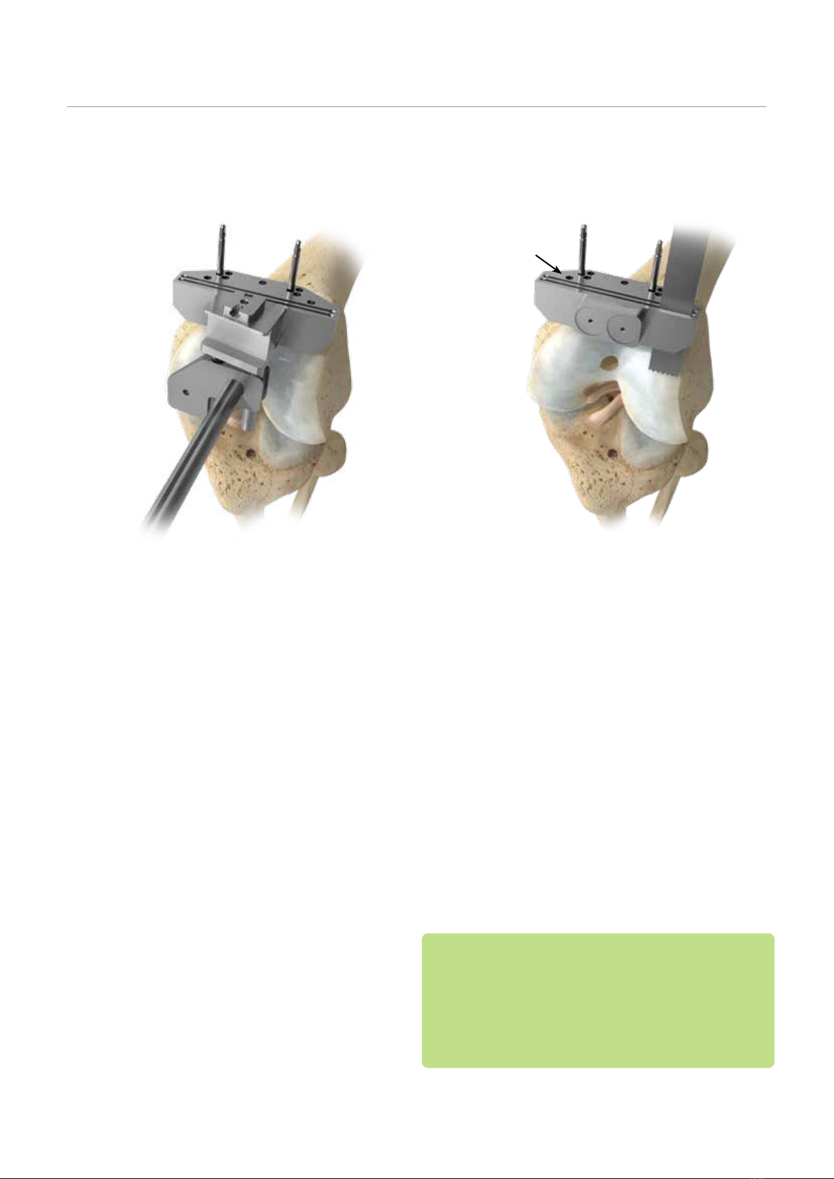
Figure 13 Figure 14Figure 12
12
VANGUARD XPTotal Knee System
Note: To confirm the valgus angle, the alignment handle
can be inserted into the adjustable distal adaptor and a 1/4"
alignment rod can be inserted and extended to the center of
the femoral head.
• Remove the valgus wing by removing the IM rod and
pulling the valgus wing and valgus block adaptor
distally away from the distal cut block, leaving the distal
cut block in place.
• Use a 1.37 mm saw blade to complete the distal
resection through the selected 0 slot (Figure 13).
eXPert Advice:
• When resecting the distal femur, ex the knee beyond 90
degrees toavoidcutting theACLwhenthe sawbladeexits
the posterior bone.
• It is strongly recommended to resect only 2-3 mm of
cartilage/bone from the femoral notch to respect the
natural joint line when the ACL is intact.
• Check the resected distal femur using a at instrument
surface to conrm a at resection.
• Recut or le as necessary to achieve proper resection.
Femoral Preparation
Distal Femoral Resection (cont.)
Option 2: Fixed Distal Femoral
Resection Guide
• Choose the appropriate left or right valgus wing (from
32-485004 to 32-485007) and assemble it onto the
IM rod by sliding it through the central hole.
• Slowly introduce the IM rod to the femoral canal to
depressurize the canal.
• Slide the valgus wing until it rests ush with the
distal femur:
- The “left” or “right” engraving on the block must face
distally corresponding to the leg being prepared.
• Slide the distal cut block and valgus block adaptor
(from 32-485014 to 32-485017) into the anterior holes
of the valgus wing until the resection block contacts
the anterior femur.
• Pin the distal cut block into place using 1/8" quick
release drill pins in the center pin holes of the block
(Figure 12).
9 mm
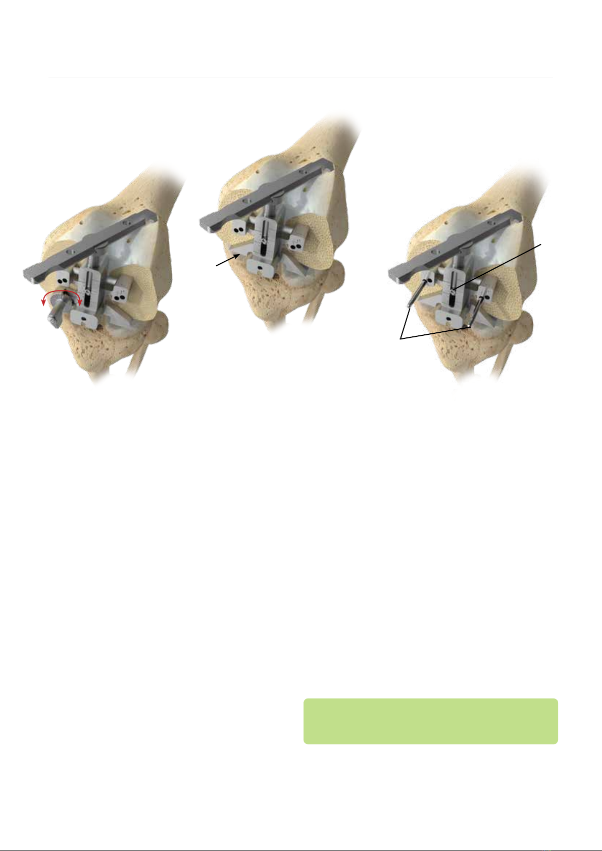
Figure 14 Figure 16
Figure 15
Fixed
B
A
13
Femoral Sizing
• Assemble the selected right or left A/P sizer feet to the
A/P sizer body (32-485050).
• Feet options are:
- Adjustable A/P sizer dial feet, left (32-700374) and
right (32-700373) with the ability to set external
rotation from 0 to 10 degrees (Figure 14).
- Fixed 3 degree A/P sizer feet, left (32-700372) and
right (32-700371) (Figure 15).
Note: Assessing the A/P femoral axis, the epicondylar axis,
exion gap and the tibial shaft axis can further optimize
femoral rotation.
• Due to the tight space, hyperex the knee to place the
A/P sizer ush with the resected femoral distal surface.
• Drill the two 4-in-1 cutting block location holes utilizing
the 1/8" quick release drill pins (32-467619) (Figure 16A).
• Leave the pins in place.
• The femoral component size can now be read from the
central scale (Figure 16B).
eXPert Advice: If the size indicated is in-between sizes,
use the smaller of the two sizes, in order to not overstu
the patellar femoral joint space.
• Remove the pins and the A/P sizer.
Femoral Preparation
^00
A
B
Figure 17 Figure 18
A
14
VANGUARD XPTotal Knee System
eXPert Advice: A narrow (approximately 12–13 mm) saw
blade should be used for the posterior and posterior
chamfer resections to prevent saw blade contact with the
ACL protector.
• When making the posterior bone and posterior chamfer
resections, the narrow sawblade should not be angled
behind the ACL protector and extra care should be
taken to protect the ACL.
Note:
• After making the anterior resection, inspection of the
anterior resection relative to the anterior cortex can
be assessed.
• Ifdownsizingispossible,theinitialblockcanberemoved
and the smaller sized block replaced. The anterior
femur and chamfer then can be resected.
eXPert Advice: A femoral notchplasty should be
performed to removeosteophytes, increasing visualization
of the femoral notch to ensure the ACL has adequate
clearance.
4-in-1 Femoral Cuts
• Choose the Vanguard XP femoral 4-in-1 block that
matches the selected size (from 32-700000 to 32-
700010) (Figure 17A).
• Assemble the ACL protector (32-700370) into the back
of the femoral 4-in-1 block (Figure 17B).
• Place the block into the 1/8" distal femur holes.
Note: A 1.37 mm feeler blade (32-486000) can be used to
determine the amount of anterior bone resection.
• Ensure the block is sitting ush against the distal femur
with the ACL protector secured in place.
• If additional stability is required, 1/8" quick release
drill pins (32-467619) or the threaded headed pins
(32-700380) can be placed in the angled side holes
provided on the femoral 4-in-1 block (Figure 18A).
• Once the block position is satisfactory, resect the
anterior and posterior bone and the anterior and
posterior chamfers with a 1.4 mm thick saw blade in a
standard and narrow conguration (Figure 18).
Femoral Preparation

Figure 20
Figure 19 Figure 21
15
Tibial Preparation
Tibial Resection with Intact/
Functional ACL
• Select the appropriate tibial island template
(from 32-700421 to 32-700425) by placing the guide on
the native tibia to size and set a preliminary rotation for
the tibial component (Figure 19).
• Use an alignment rod to ensure alignment with the
medial third of the tibial tubercle.
• When the appropriate size template is determined and
positioned, outline the island with a marking pen.
Resection
• Attach the tibial universal cutting block (32-700431)
(which has a 7 degrees posterior slope built-in) to the
EM tibial guide (32-700365).
• Position the EM tibial guide on the tibia and place the
spring-loaded arms of the ankle clamp around the
distal tibia just above the malleoli (Figure 20).
eXPert Advice: The three critical measurements in the
tibial resection are resection depth, slope and varus/valgus.
Care must be taken to resect adequate tibial bone and to match
the patient’s native slope for a knee with a functioning ACL.
• Posterior slope is adjusted by depressing the button
on the side of the EM tibial guide base and moving the
base forwards or backwards to allow the tibial cutting
block (with 7 degrees of slope) to replicate native slope.
The tibial posterior slope guide (32-700430) can be
used to assist in assessing slope (Figure 21).

Figure 23Figure 22
• Secure the EM tibial guide body to the tibia with one
pin (headed threaded, 32-700380) placed in either the
medial or lateral hole in the EM tibial guide yoke (not
through the cutting block) (Figure 23).
16
VANGUARD XPTotal Knee System
Tibial Preparation
Tibial Resection with Intact/
Functional ACL (cont.)
• Adjust the initial guide height accordingly by placing
the universal tibial cutting block against the proximal
tibia at the estimated resection level.
• Attach the tibial stylus (32-700072) to the tibial universal
cutting block by placing the appropriate stylus tongue
into the slot on the universal tibial cutting block
(Figure 22).
- Select 4 mm o the medial low or 12 mm o the
lateral high.
- Use the island outline marked previously to place the
tibial universal cutting block in the correct M/L
location. The center of the tibial universal cutting
block should approximately align with the center
of the island. If the tibial universal cutting guide is
placed too medially, there will be insufficient cutting
surface when making the lateral tibial resection in
subsequent steps.
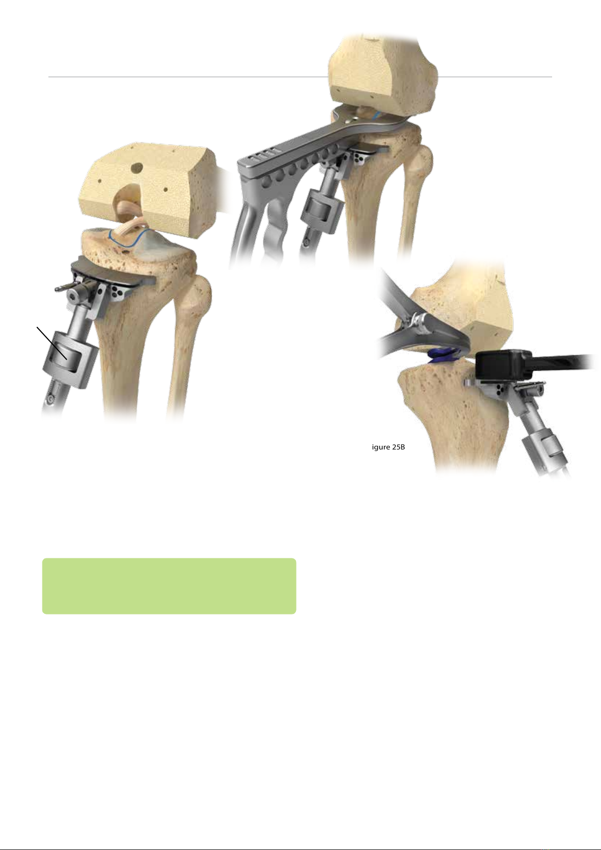
Figure 24
Fine-tune
Adjustment
Figure 25A
Figure 25B
17
Tibial Preparation
Tibial Resection with Intact/
Functional ACL (cont.)
Fine Tuning Tibial Resection Height
• Fine-tune the tibial resection level by using the height
adjustment thumb wheel (Figure 24).
eXPert Advice: Retaining the ACL tends to make the gaps
tighter than in a standard TKA. Use best judgment when
fine-tuning the resection level and when in question, take
slightly more tibial bone to avoid bone island fracture.
Option 1
• Bring the knee into extension and place the tibial
resection spacer (32-700419) tongue into the slot of the
tibial cutting block and allow the paddles to loosely rest
against the distal cut surface of the femur (Figure 25A).
• Apply traction to the leg to replicate appropriate
tension on the knee ligaments.
• Gently apply pressure to the lever toward the body
of the handle. Adequate extension space will allow
the lever to rest easily on the body of the handle. If
moderate to excessive force is needed to fully depress
the lever, adjust the depth of the tibial cutting block
to resect more tibial bone, and conrm the extension
space by easily depressing the lever to the paddle body.
• Repeat previous step at 90 degrees of exion to ensure
that exion and extension spaces match.
Option 2
• Bring the knee into extension and place a lamina
spreader in the medial joint space for a varus knee and
lateral joint for a valgus knee and tense the ligaments
to replicate appropriate tension.
• Place the 10 mm gap checker (32-700039) on the tibial
cut block surface on the medial side for a varus knee
and lateral side for a valgus knee and visually conrm
that there is adequate space between the gap checker
and the distal cut surface of the femur (Figure 25B).
• If the space is not adequate adjust the depth of the
tibial cutting block by using the ne tune adjustment
on the EM guide.
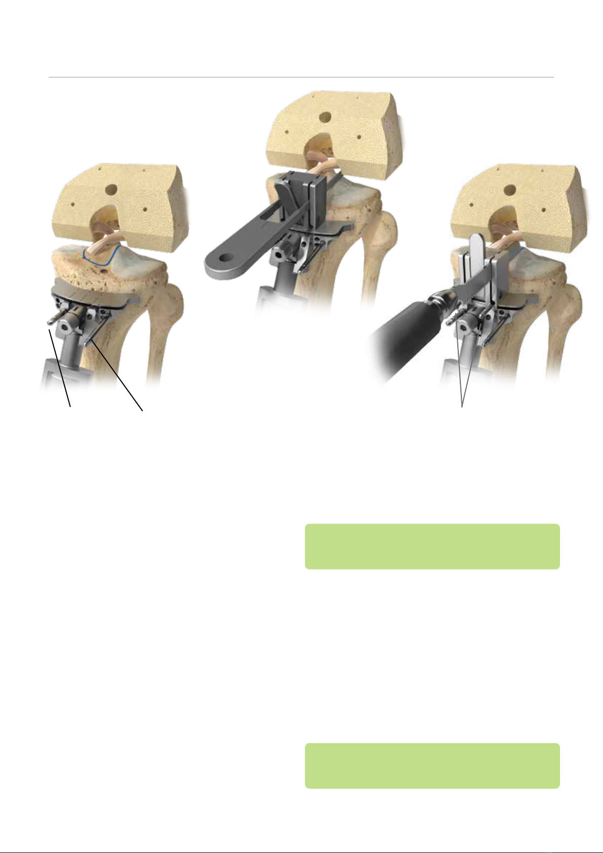
Figure 26
Standard Pin Non-headed Threaded Pin
Headed/Threaded Pin
Figure 28
Figure 27
18
VANGUARD XPTotal Knee System
Tibial Preparation
Tibial Resection with Intact/
Functional ACL (cont.)
Vertical Resection
• Remove the tibial resection spacer.
• After the horizontal resection level is set, place one 1/8"
quick release drill pin in the middle hole of one side of
the tibial universal cutting block and another one on
the opposite side (32-467619) (Figure 26).
• Insert the tibial vertical resection block captured
(32-700387) or un-captured (32-700034) in the slot of
the universal cutting block (Figure 27).
• Insert the tibial alignment guide (32-700384/385)
through the vertical resection block and island
outline. Use the ACL, femoral notch and tibial tubercle
landmarks to assist in determining rotation.
• If desired, place an alignment rod in the end of the
tibial alignment guide to verify tibial rotation.
eXPert Advice: To allow for larger tibial tray sizing, the
vertical cuts should be as far lateral as possible without
cutting the ACL.
Note:
• If the tibial component is downsized intraoperatively
from an 87 mm to an 83 mm size, the tibial bone island
will have to be recut to the appropriate size.
• Lock the vertical resection block by lifting the lever
into its upright position and pinning the block in place
using two headless threaded pins (32-700379).
• With a reciprocating saw blade, cut down to the
threaded pins; the pins will act as a saw stop. Ensure
the vertical resection extends from the anterior cortex
through the posterior cortex (Figure 28).
eXPert Advice: To prevent the reciprocating blade from
skiving, advance the blade in small increments, raising the
tip first and resecting downward.
Table of contents
Other BIOMET Medical Equipment manuals


Popular Medical Equipment manuals by other brands

Biovision Veterinary Endoscopy
Biovision Veterinary Endoscopy NeedleView 4000 LD user guide

DITABIS
DITABIS HLC AA 02 operating manual

Stryker
Stryker HeartSine Gateway LIFELINKcentral user manual

medi
medi Stabimed manual

PhotoniCare
PhotoniCare TOMi Scope Quick Start Pocket Guide

Kodak
Kodak Miniloader 2000 Service manual


