BIOMET 2001A User manual
100 Interpace Parkway • Parsippany, NJ 07054
800.526.2579 • www.biomet.com • 1068012L Rev B
©2010 EBI, LLC. All trademarks are the property of Biomet, Inc.or its subsidiaries
unless otherwise indicated. Velcro®is a registered trademark of Velcro Industries, B.V. Rx Only.
EC REP
Authorized European Representative
Biomet UK Ltd.
Waterton Industrial Estate
Bridgend
C 31 3XA UK

Non-Invasive Stimulation
OPTIONS • EVIDENCE • EXPERIENCE
EBI Bone Healing System®
Model 2001
User Manual and
Package Insert

IMPORTANT SAFEGUARDS
READ A INSTRUCTIONS BEFORE USING
When using electrical products, basic safety precautions should always
be followed, including:
WARNING: To reduce the risk of electric shock, fire or potential injury:
1. Do not use while bathing.
2. Do not place or store product where it can fall or be pulled into
a tub or sink.
3. Do not immerse the control unit, coil, battery charger/power unit, or the
battery charger cradle in any liquid.
4. Do not reach for a product that has fallen into a liquid.
Unplug from the wall outlet immediately.
5. Do not permit the battery charger to be connected when wet.
6. Do not drop the control unit, coil, battery charger/power unit, or
the battery charger into any liquid.
7. Avoid touching the battery contacts when the battery charger cradle is
plugged into an outlet.
8. Do not place the battery charger cradle in the bed with you if you are
using the unit while you are sleeping.
9. Never operate this product if it has a damaged link cable, cord or plug,
if it is not working properly, if it has been dropped and damaged, or
dropped into any liquid. Return the product to EBI.
10. Keep all cords away from heated surfaces.
11. Never insert any object into any opening of the system.
12. Do not place the control unit or the battery charger in prolonged heat
or direct sunlight (Normal operating temperature range is 0°C to 38°C,
[32° to 100° ], normal storage/transport temperature is -15°C to 45°C
[5° to 113° ]).
13. Connect this product to a properly grounded outlet
(See GROUNDING INSTRUCTIONS).
14. Use this product only for its intended use as described in this manual.
15. Medical Electrical Equipment needs special precautions regarding
Electromagnetic Compatibility (EMC) and needs to be operated according to the
EMC information provided in this instruction manual.
NOTE: Call the Biomet Patient upport Department in New Jersey
between 8:30 a.m. and 6:30 p.m. Eastern Time at 1-973-299-9300 with
any questions or problems. Outside the United tates contact your local
EBI/Biomet Distributor.
SAVE THESE INSTRUCTIONS
Contents:
Model 2001 Control Unit
LX®Treatment Coil with straps (if applicable)
Connector cables
Belt and Pouch (if applicable)
Recharger base
Recharger Power Supply
User Manuals (2)
LX®Gauge
Travel Card
Carrying Case
Caution: Federal aw (U.S.A.) restricts this device to sale by or on the order of a physician.
For Prescription Use Only.

TAB E OF CONTENTS
IMPORTANT SA EGUARDS & CONTENTS........................................Inside ront Cover
TABLE of CONTENTS....................................................................................................1
EBI BONE HEALING SYSTEM®Stimulator....................................................................3
• Description ............................................................................................................3
• Electrical Requirements..........................................................................................3
SYSTEM COMPONENTS ..............................................................................................4
ULL PRESCRIBING IN ORMATION ............................................................................5
• Indications or Use ................................................................................................5
• Contraindications, Warnings ..................................................................................5
• Precautions, Adverse Effects ..................................................................................6
• Directions or Use..................................................................................................6
• racture Healing in Response to PEM S ................................................................7
OPERATING INSTRUCTIONS ..................................................................................8-17
• STEP 1: Battery Charging....................................................................................8-9
• STEP 2: Preparing the System to Begin Treatment ..............................................10
• STEP 3: Treating and Charging ............................................................................11
• STEP 4: Recharging the Batteries ........................................................................11
• KEYPAD UNCTIONS ......................................................................................13-15
• TROUBLESHOOTING SYSTEM MESSAGES ....................................................15-17
LX®LEXIBLE TREATMENT COILS ..........................................................................18
• LX®-1, LX®-2, LX®-3, LX®-4 and LX®-5 Coil Application, Instructions ....19-20
• Conforming the LX®Coil ....................................................................................21
• Casted Applications ..............................................................................................22
• Noncasted Applications ........................................................................................23
• lexion Gauges................................................................................................24-28
LX®1-1 OR 2-1 OR 4-1 LONG VERTICAL RACTURE APPLICATION ......................29
• Coil Application Instructions ................................................................................29
• lexion Gauge Instructions for LX®1-1, LX®2-1 & LX®4-1 Coils ..................30
• lexion Gauges................................................................................................31-33
LX®1-2, 2-2 Metatarsal Application ........................................................................34
• Coil Application Instructions ................................................................................34
• lexion Gauge Instructions for LX®1-2 & LX®2-2 Coils ..................................35
• lexion Gauges................................................................................................36-37
LX®1-3 OR 2-3 CLAVICLE APPLICATION ................................................................38
• lexion Gauge Instructions for LX®1-3 & LX®2-3 Coils ..................................39
• lexion Gauges................................................................................................40-41
LX®2-4 AND 4-4 ANKLE/ELBOW APPLICATION ......................................................42
• lexion Gauge Instructions for LX®2-4 & LX®4-4 Coils ..................................44
• lexion Gauges ....................................................................................................45
LX®2-5 OR 3-5 OR 4-5 PROXIMAL HUMERUS/SHOULDER APPLICATION ............46
• lexion Gauge Instructions for LX®2-5, LX®3-5 & LX®4-5 Coils ..................47
• lexion Gauges................................................................................................48-49
1

2
TAB E OF CONTENTS
ANKLE APPLICATION - LX®-XL Coilette ..................................................................50
HAND APPLICATION - LX®-XL Coilette ....................................................................51
LX®-XL lexion Gauge ..............................................................................................52
CLAVICLE PLACEMENT APPLICATION INSTRUCTIONS ......................................53-54
• lexion Gauge Instructions for LX®lexible Treatment Coilette -Clavicle............55
• Phalange Coil Application Instructions for the LX®-Mini ....................................56
• lexion Gauge Instructions for LX®-Mini Coil......................................................56
• EBI Bone Healing System®LX®-Mini Coilette Instructions..................................57
• lexion Gauge ......................................................................................................58
• lexion Gauge Instructions for the LX®Standard Coilette ..................................59
• Coil Application Instructions for the LX®-Standard........................................59-62
• lexion Gauge ......................................................................................................63
CLEANING INSTRUCTIONS........................................................................................64
TREATMENT COMPLETION........................................................................................64
DISPOSAL INSTRUCTIONS........................................................................................64
EQUIPMENT CLASSI ICATION ..................................................................................65
SYMBOL DESCRIPTION ............................................................................................65
ORDERING IN ORMATION ........................................................................................66
RE ERENCES ............................................................................................................66
REPLACEMENT COMPONENTS..................................................................................67
ELECTROMAGNETIC COMPATIBILITY ..................................................................68-71
QUESTIONS AND ANSWERS................................................................................72-73
3
EBI Model 2001 Bone Healing System®
Model 2001 and F X®Flexible Treatment Coil
Caution: Federal aw (U.S.A.) restricts this device to sale by or on the order
of a physician. For Prescription Use Only. Single prescription. Single patient
use. Not for re-sale, re-use or re-distribution.
DESCRIPTION
The EBI Bone Healing System®Stimulator promotes healing by inducing weak pulsing
electrical currents at the nonunion fracture site. These signals are generated by a low energy
electromagnetic field created by passing specific electrical current pulses through a flexible
treatment coil.
Electrical Requirements of Model 2001 Power Unit – USA/Americas
Input: 120V 60Hz 36W
Output: 17.8V 1.5A.
Do not use any other power unit with the Model 2001 Bone Healing System.
E ECTRICA REQUIREMENTS
Use the following power adapters with the Model 2001 Bone Healing System.
Input: 240V 50Hz 36W
Output: 17.8V 1.5A
Model 2001E Europe
Input: 230V 50Hz 36W
Output: 17.8V 1.5A
Model 2001J Japan
Input: 100V 50Hz 36W
Output: 17.8V 1.5A
Model 2001U United Kingdom
Input: 240V 50Hz 36W
Output: 17.8V 1.5A
Model 2001A Australia
4
Not for use by patients who are pregnant or becoming pregnant
Not recommended for patients with certain types of pacemakers or implantable defibrillators
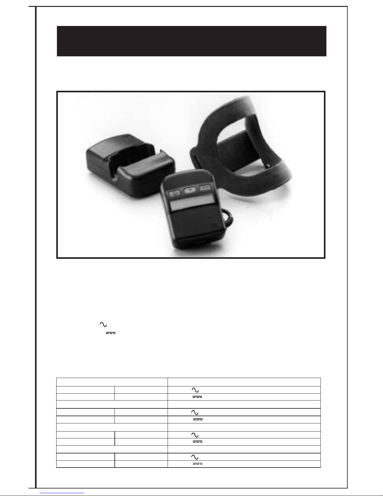
SYSTEM COMPONENTS
CONTRO UNIT
The EBI Bone Healing System®Stimulator control unit operates on nickel metal hydride,
rechargeable batteries which allow for ambulatory use. The control unit contains the operating
electronics programmed for the LX®lexible Treatment Coil. It includes an audible and visible
self checking alarm mechanism to alert the patient if the unit is not functioning properly.
The control unit is designed to store the patient’s daily usage information. Patients are
encouraged to bring the control unit and treatment coil to each follow-up visit to allow the
prescribing physician to review their treatment regimen.
NOTE: The control unit may be worn comfortably on a belt or the waist using the Belt Pouch
when the patient is ambulatory.
BATTERY CHARGER CRAD E
The battery charger cradle is powered by the battery charger/power unit adaptor and is
designed to recharge the control unit batteries. Its design also allows the control unit to be
used in a treat and charge situation (i.e., while sleeping, sitting) (See TREATING AND
CHARGING STEP 3 pg. 11).
BATTERY CHARGER/POWER UNIT
The battery charger/power unit is powered by normal house current and is designed to provide
power to the charger cradle. Power unit must be unplugged from wall outlet to be disconnected.
INK CAB E
The link cable connects the control unit to its LX®lexible Treatment Coil. The link cable
supplied is a 33” (83.8cm) cable. Link cables are also available in 12” and 48” lengths. or
either a 12” (30.5cm) or 48” (121.9cm) cable, phone the Biomet Patient Support Department
at 1-973-299-9300. Outside the United States contact your local EBI/Biomet Distributor.
F X®F EXIB E TREATMENT COI
The LX®lexible Treatment Coil is an encased wire coil that may be incorporated into a cast,
over a cast or brace, or when a cast is not utilized, may be applied directly to the skin. A spe-
cific electrical current is delivered to the coil by the control unit. The coil then delivers the ther-
apeutic electromagnetic signal to the nonunion fracture site.
GROUNDING P UG
This product is equipped with a grounding plug with the exception of the Model 2001E. The
battery charger/power unit should be plugged into a wall outlet that is properly installed and
grounded. In the event of an electrical short circuit, grounding reduces the risk of electric
shock by providing an escape wire for the electric current.
If it is necessary to use an extension cord, use an extension cord that has a 3-blade grounding
plug and a 3-slot receptacle that will accept the plug on the product. Do not use damaged
cords.

1. Bassett CAL, N Caulo and J Kort, “Congenital pseudarthrosis of the tibia: Treatment with pulsing
electromagnetic fields”. Clinical Orthop, 154: 136-149,1981.
FU PRESCRIBING INFORMATION
The mechanism of action behind the PEM technology involves the upregulation of factors
that modulate normal bone healing. PEM increases a number of factors such as TG - ß1,
BMP-2 and BMP-4, which are normal physiological regulators of the various stages of bone
healing, including angiogenesis, chondrogenesis and osteogenesis.
INDICATIONS FOR USE
The EBI Bone Healing System®Stimulator is indicated for the treatment of fracture nonunions,
failed fusions, and congenital pseudarthrosis in the appendicular system. A nonunion is
considered to be established when there are no visibly progressive signs of healing. The
original 1979 PMA study included 146 patients with nonunion fractures. These difficult
fractures were characterized as follows: 2.3 average number of prior surgeries and an average
of thirty-seven months (median twenty months) since original injury. These patients were
followed for a minimum of four years (average seven years) from the date of treatment
termination, with a success rate of 63.5%. Even though long term follow-up requirements
were not included in the original study designs, a follow-up rate of 82% was achieved.
orty-three (43) of the original 48 patients in the congenital pseudarthrosis study were
classified by Bassett1who defined the tibial lesions as Type I (n=6), Type II (n=19) and
Type III (n=18), with Type III being the most severe and recalcitrant to treatment. The
success rate for Bassett Type I lesions was 66.7%, Bassett Type II lesions 57.9% and
Bassett Type III lesions 22.2%. The long term post treatment follow-up for the congenital
pseudarthrosis study patient population (n=48) was to skeletal maturity or the age of 18.
The study had an 87.5% follow-up rate.
CONTRAINDICATIONS
A. Nonunion fractures in which a synovial pseudarthrosis (fluid filled gap) exists.
B. Under certain conditions, electromagnetic stimulation could inhibit the output of some
demand pacemakers or implantable defibrillators. Therefore, it is not recommended for
patients with certain types of pacemakers or implantable defibrillators. Patients should
be cautioned to avoid coming in close proximity to pacemaker or defibrillator wearers
during stimulation.
C. Use of the EBI Bone Healing System®Stimulator on pregnant patients has not been
evaluated; therefore, it is not recommended in these cases.
WARNINGS
A. The long term effects of exposure to low level magnetic fields are not known. Routine
use of The EBI Bone Healing System®Stimulator for over 20 years has indicated no
known risks.
B. During the treatment of patients with open epiphyses, when the epiphysis is in the
pulsing field, physicians are advised that the epiphyseal growth plates should be
monitored for possible effects.
C. Use of the EBI Bone Healing System®Stimulator for spine and skull has not been
evaluated.
D. To reduce the risk of potential injury:
1. AVOID touching the battery charger contacts when the battery charger
is plugged into a wall outlet.
2. DO NOT place the battery charger in bed if treating while sleeping.
E. The control unit and battery charger are electrically live when connected
together and the battery charger is plugged into an outlet. To reduce the
risk of serious injury by electric shock patients are advised:
1. DO NOT permit the battery charger to be connected when wet.
2. DO NOT immerse the control unit, the coil or the battery charger in water or any liquid.
5

PRECAUTIONS
The following conditions may compromise a successful treatment outcome.
A. Nonunion fractures with gaps in excess of 1 cm.
B. Presence of fixation devices made from magnetic materials.
(Most presently used internal or external fixation devices are
constructed of 316L S.S., titanium alloys, and cobalt-chromium
alloys which are non-magnetic and, therefore, compatible with
the EBI Bone Healing System®Stimulator.)
ADVERSE EFFECTS
None known.
6
DIRECTIONS FOR USE
ollow the treatment schedule prescribed by your doctor - normally ten (10) hours per day.
Your compliance with the recommended ten (10) hours per day treatment is very important. A
review of the clinical data demonstrates that less than the recommended use of this device
possibly results in an increase in the time to heal your fracture. (P790002/S012)
If you are unable to treat for ten continuous hours, it is recommended that you break up the
total treatment time into more than one session.
You should:
• Turn the control unit off when finished with your session
• When ready to resume treating, turn the control unit on. The display will indicate the
treatment time you have completed and keep track of your cumulative treatment time for the
day
• If you do not finish ten hours in that day, then use the RESET button to return the time to
zero (See RESET BUTTON)
Remember, if the treatment is administered longer than the prescribed amount (ten hours), the
additional time cannot be applied for future days. Example: If you used the system for multi-
ple sessions totaling 14 hours one day, you should not abbreviate the next day’s cumulative
treatment time to six hours.
or your convenience, your daily treatment time is displayed continuously in hours and
minutes. After ten hours of treatment, the display will read “10:00”, and beep three (3) times,
and then shut off automatically.
ollowing completion of your daily treatment, you should do the following:
1. Make sure the control unit is off. If you have completed 10 hours, the unit will
automatically shut off. With less than 10 hours of treatment, you will need to manually
turn the control unit off.
2. Insert the control unit firmly into the battery charger cradle to recharge the batteries for
your next treatment (See BATTERY CHARGING).

7
FRACTURE HEA ING IN RESPONSE TO PEMFs
• Unlike fresh fractures, the healing of nonunions treated with pulsing electromagnetic fields
(PEM s) does not involve external callus formation. Rather, the healing is more endosteal or
“inside out”, with the changes occurring within the fracture gap tissues and in the adjacent
bone ends.
The bone healing process typically progresses in the following manner under PEM treatment:
• Triggering calcification of the fibrocartilage in the fracture gap is an early PEM
effect. Radiographically this calcification is evidenced by the appearance of
fuzziness in the gap space. The fuzziness varies in amount and rate of appearance.
Concurrently, new blood vessels penetrate the calcified fibrocartilage, and the
sclerotic bone flanking the gap begins to resorb (sclerolysis). These effects are
normally observed approximately one to three months after treatment is initiated.
NOTE: This early healing may be disrupted by injudicious loading and motion due to
inadequate immobilization.
The EBI Bone Healing System®Stimulator may be used at home or at work. Your schedule
and lifestyle will determine the best time for using the system. Many people find it convenient
to treat while they are sleeping.
• EBI Pre Market Approval Data (P790002/S012)
NOTE: This is a single patient use device, do not reuse. or Prescription Use Only. The EBI
Bone Healing System®Stimulator is a durable therapeutic electrical device intended for single
patient use only under a prescription. Treatment at home or in another appropriate or similar
setting is acceptable. The device cannot be reprocessed, i.e., disinfected, sterilized, etc. with
the intent to be used by another patient or for treatment other than prescribed.
RECOMMENDED CONCURRENT FRACTURE MANAGEMENT
The EBI Bone Healing System®Stimulator works best when motion of the fracture site is
minimized or nonexistent. or most patients this immobilization is achieved by applying a well
molded plaster or synthetic cast at the beginning of treatment (together with initial
non-weight bearing, if it is the lower extremity).
The following methods of fracture immobilization have been most effective:
• ankle/tarsals/metatarsals: short leg cast, or rigid internal fixation
• tibia: long leg cast (short leg cast with rigid fixation), or stable
internal fixation or external fixation
• shoulder/clavicle: brace or abduction splint or internal fixation or
figure 8 immobilization
• humerus: stable internal fixation and/or adequate immobilization with controlled rotation
• scaphoid/wrist: long arm cast with thumb spica
(short arm cast with rigid fixation), or stable internal fixation
• carpals/metacarpals/phalanges: cast or internal fixation or external fixation
WEIGHT BEARING GUIDE INES
Immediate weight bearing is recommended for “stable” fractures (less than five degrees
of motion in any plane and/or stable internal fixation). Initial non-weight-bearing is
recommended for “unstable” fractures (greater than five degrees of motion).
Allow six to twelve weeks for the progression of trabecular bridging with the
counterproductive effects of tensile loading ( uzziness at the fracture gap will be noted
radiographically).
8
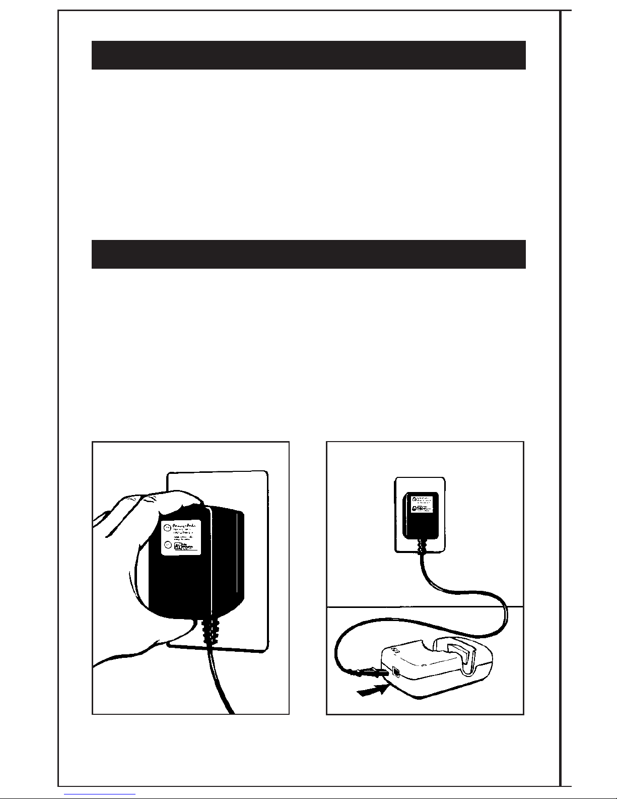
STEP 1:
BATTERY CHARGING
The EBI Bone Healing System®Stimulator runs on nickel metal hydride batteries. Before
treating with the system, the patient will need to charge the batteries to a full charge. At room
temperatures (24˚C [75˚ ]), charging may take up to two hours. In warm temperatures (29˚C
[85˚ ]), the unit may take up to five hours to charge.
Plug the battery AC charger/power unit
into a grounded wall outlet. Attach battery AC charger/power unit to
the battery charger cradle.
AB
FRACTURE HEA ING IN RESPONSE TO PEMFs (cont’d)
• The second stage of healing is indicated by the appearance of consolidated
bone stress lines that bridge the fracture gap. This bridging may appear initially,
but should progress until cortical continuity occurs in all cortices as visualized on
AP and lateral x-rays. Once cortical continuity is established and clinical union
occurs (i.e. no motion), the PEM s treatment may be discontinued. These effects
are normally observed approximately three to eight months after treatment is
initiated. At this point, the patient should be put on a program of guarded
rehabilitation to prevent refracture.
• Subsequent remedullarization and remodeling occurs according to Wolff’s Law
and may take from twelve to twenty-four months to complete.
OPERATING INSTRUCTIONS
Before using the EBI Bone Healing System®Stimulator for the first time, the control unit
should be charged.

9
The control unit display will read
“CHARGING”. When the control unit
is fully charged, the display will read
“ ULLY CHARGED”. The EBI Bone Healing
System®Stimulator is now ready for daily
treatment.
A green light on the cradle will
illuminate indicating that the charger
is connected to household power.
Place the control unit into the battery
charger cradle as illustrated. Make sure
the control unit is turned off.
Remove the control unit from the battery
charger cradle. The control unit is now
ready for connection to the link cable and
treatment coil.
CD
EF
ULLY CHARGED
CHARGING

10
STEP 2:
PREPARING THE SYSTEM TO BEGIN TREATMENT
The link cable arrives disconnected from the control unit.
Connect one end of the link
cable to the control unit cable
as illustrated.
After confirming that the link cable is properly
connected to the control unit, connect the other
end of the link cable to the LX®lexible Treatment Coil.
This connection allows for simple quick disconnect and
reconnect by the patient.
Next, position the LX®lexible Treatment Coil over the fracture
site. The entire fracture site should be centered within the coil
treatment window.
AB
C

11
STEP 4:
RECHARGING THE BATTERIES
The average daily treatment time supplied by the batteries in the control unit will vary according
to the size of LX®coil being used. All coils should deliver a minimum treatment time of ten
hours per charge, except the LX®5, which will deliver five hours of treatment per charge. At
room temperatures (24°C [75° ]), charging may take up to two hours. In warm temperatures
(29°C [85° ]), the unit may take up to five hours to charge.
Aft r daily tr atm nt, pati nts should do th following:
A. Turn the control unit off.
B. ollow instructions A-E from Step 1 (Pages 8 & 9).
C. It is not necessary to disconnect the control unit from the charger cradle
once fully charged. The control unit can remain in the battery charger cradle
until the patient’s next treatment session.
NOTE: The batteries cannot be overcharged. If the control unit is in the battery charger cradle
and the batteries are already fully charged, the charger will terminate the recharging process
early. This will be indicated by the control unit display reading “FULLY CHARGED” when
charging is complete. Therefore, do not be concerned if the batteries are inadvertently
charged more than once.
STEP 3:
TREATING AND CHARGING
Patients may treat with the system while recharging the batteries. When the patient treats and
charges at the same time, the treatment time and charging message will be displayed. To treat
and charge, patients should:
1. Turn the control unit on.
2. ollow instructions A - E from Step 1. (Page 8)
NOTE: If treating while the control
unit is connected to the battery
charger cradle, the control unit display
will read “TREATING 00:00 and
CHARGING”. Once the patient has
completed the treatment, he should
turn the control unit off, and leave it
connected to the battery charger cradle
to continue charging the batteries, if it
is not displaying “FULLY CHARGED”.
TREATING 00:00
AND CHARGING
12
Wh n th batt ri s n d r charging, th following will occur:
1. The display will read “RECHARGE
BATTERY” and 10 short beeps will
sound. After 10 seconds, the beep
will stop and the display will shut off.
2. Until the batteries are recharged,
“RECHARGE BATTERY” will appear
on the display each time the control
unit is turned on. After the third time
the patient turns the unit on without
recharging, “RECHARGE BATTERY”
will appear and alternate with “PLEASE
CALL EBI 1-800-526-2579”. If patients
need assistance with recharging, they
should call the 800 number and ask to
speak to a Patient Support Representative.
Outside the United States contact your
local EBI/Biomet Distributor, or
call 1-973-299-9300.
3. Only after the patient places the control unit
into the battery charger cradle for recharging
will the message automatically clear.
4. When the control unit has been
fully charged, it may be removed
for ambulatory treatment, or left
in the battery charger cradle and
turned on for nonambulatory use.
NOTE: Every 14 days the charger will
automatically refresh the batteries by
completely depleting them before it begins
charging. When this occurs, the control
unit display will read “REFRE HING”.
Once the system has refreshed the
batteries, the control unit display will read
“CHARGING”, and the charging process
will begin. The refresh mode will take a
few hours depending on the size of the
LX®Flexible Treatment Coil being used.
CHARGING
RE RESHING
Alt rnat s with
RECHARGE BATTERY
PLEASE CALL EBI
1-800-526-2579

13
KEYPAD FUNCTIONS
ON/OFF BUTTON
Each time the ON/O button is pressed, an audible beep will be heard. To turn the control
unit on, press the on/off button one time. Pressing this button a second time will turn the
system off. Every time the control unit is turned on, the display will indicate the following
sequence:
1. “EBI RECOMMENDS 10 HOURS PER DAY” for the 2001 BHS.
2. “AVG HR/DAY 00:00” - This is the daily treatment average
since the patient’s treatment started.
3. “DAYS USED 000” - This is the total number of days of treatment.
4. “DAYS UNUSED 000” - This is the total number of days when
there was no treatment.
5. “TREATING 00:00” - This is the cumulative number of hours
of treatment in the present or previous treatment session,
provided that the reset button has not been pressed
(see RESET BUTTON).
1.
2.
3.
4.
5.
EBI RECOMMENDS
10 HOURS PER DAY
PATIENT USAGE
AVG HR/DAY 00:00
PATIENT USAGE
DAYS USED 000
PATIENT USAGE
DAYS UNUSED 000
TREATING 0:00
14
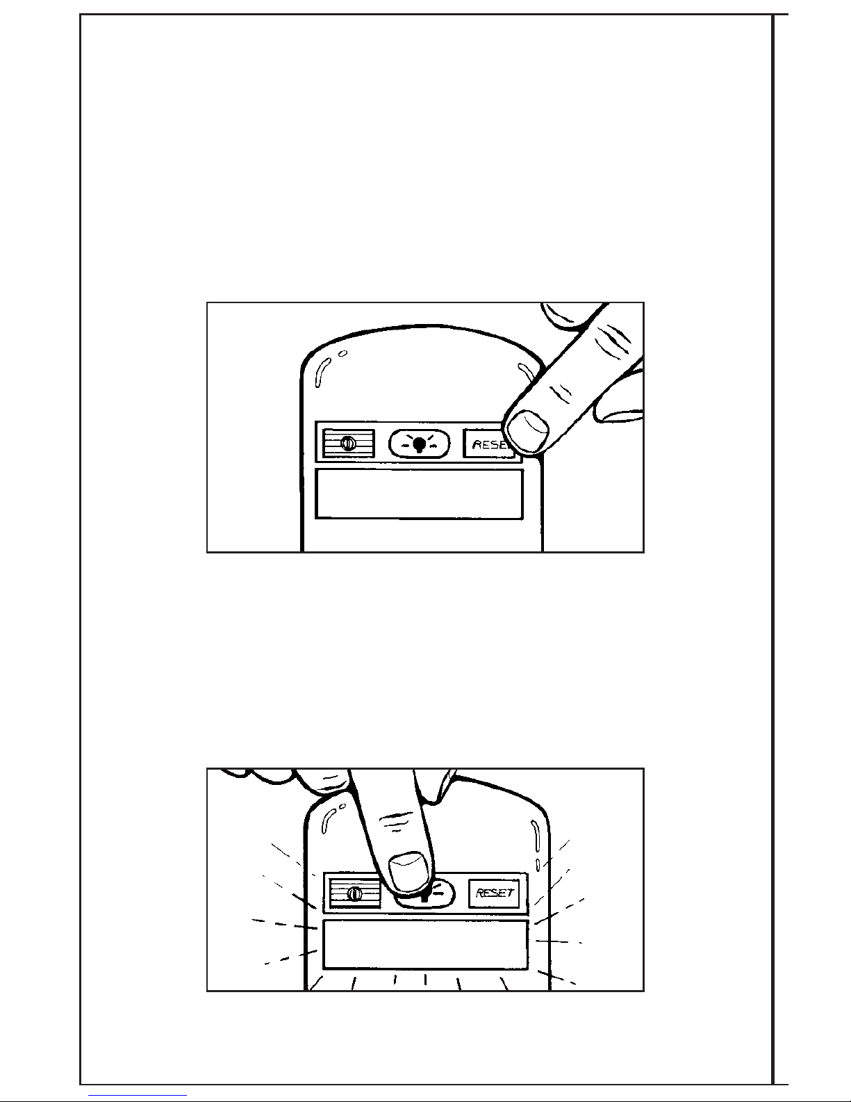
RESET BUTTON
The system is designed with a reset function to allow the daily timer to be reset to zero.
Should the patient not finish the ten hours of treatment in one day, he/she presses the RESET
button for two (2) beeps and the daily timer will go back to zero in preparation for the next
treatment session. The treatment time will be retained on the display unless the RESET button
is depressed for two audible beeps.
To avoid the accidental reset of the daily time, the RESET button has a one second delay.
When pressed, the RESET button will beep. To clear the time back to zero, continue holding
the button until a second beep is heard (approximately one second). Release the RESET
button. This will clear the time back to 0:00. The display will then read “TREATING 0:00”.
BACK IGHT BUTTON
The system is designed with a backlight function to enhance the visibility of the LCD display
in dim lighting. When pressed the BACKLIGHT button will beep, and the backlight will turn on
for 5 seconds.
TREATING 0:00

15
TROUB ESHOOTING SYSTEM MESSAGES
Allow up to one minute for the display message to change after taking corrective action.
• “RECHARGE BATTERY” If this message appears, the batteries need to be recharged.
This message will only appear during a treatment session. In order to recharge the
batteries and continue treatment, ensure that the control unit is on. Refer to Step 4
“RECHARGING THE BATTERIES” (P. 11), repeating 1-4.
RECHARGE BATTERY
ollowing completion of your daily treatment, you should do the following:
1. Make sure the control unit is off. If you have completed 10 hours, the unit will
automatically shut off. With less than 10 hours of treatment, you will need to manually
turn the control unit off.
2. Insert the control unit firmly into the battery charger cradle to recharge the batteries for
your next treatment (See BATTERY CHARGING).
The EBI Bone Healing System®Stimulator may be used at home or at work. Your schedule
and lifestyle will determine the best time for using the system. Many people find it
convenient to treat while they are sleeping.
16
“CHECK CONNECTORS SEE MANUA ”
This message, accompanied by 10 short audible
beeps, appears when the control unit is not
properly connected to the LX®lexible
Treatment Coil. Be sure to check all connections
between the control unit, link cable and the
treatment coil. If the connection is not made,
the unit will turn itself off. When the unit is
turned back on and the message continues,
check all connections again. If the problem is
not corrected and the connection is not made,
the message will stay on the display for 10
seconds and then turn off each time the control unit is turned on. After the third time of
turning the unit on without correcting the problem, “CHECK CONNECTORS SEE MANUAL” will
appear and alternate with “PLEASE CALL EBI 1-800-526-2579”. If you need assistance, you
should call the 800 number and ask to speak to a Patient Support Representative. Outside the
United States contact your local EBI/Biomet Distributor, or call 1-973-299-9300.
”CHECK COI SEE MANUA ”
This message, accompanied by ten short audible
beeps, appears when the LX®lexible Treatment
Coil is damaged or inappropriately flexed. The
message will stay on the display for 10 seconds
and then turn off each time the control unit is
turned on. After the third time of turning the unit
on without correcting the problem, “CHECK COIL
SEE MANUAL” will appear and alternate with
“PLEASE CALL EBI 1-800-526-2579”. If you
need assistance, you should call the 800 number
and ask to speak to a Patient Support
Representative. Outside the United States contact
your local EBI/Biomet Distributor, or call 1-973-299-9300.
“CANNOT TREAT P EASE CA EBI 1-800-526-2579”
This message, accompanied by ten short audible
beeps, appears when there is a hardware
problem within the control unit. The message
will stay on display for 10 seconds and then turn
off each time the control unit is turned on. After
the third time of turning the unit on without
correcting the problem, “CANNOT TREAT” will
appear and alternate with “PLEASE CALL EBI
1-800-526-2579”. If you need assistance, you
should call the 800 number and ask to speak to
a Patient Support Representative. Outside the United
States contact your local EBI/Biomet Distributor, or
call 1-973-299-9300.
CHECK CONNECTORS
SEE MANUAL
PLEASE CALL EBI
1-800-526-2579
Alt rnat s with
CANNOT TREAT
PLEASE CALL EBI
1-800-526-2579
Alt rnat s with
CHECK COIL
SEE MANUAL
PLEASE CALL EBI
1-800-526-2579
Alt rnat s with

17
“CANNOT CHARGE P EASE CA EBI 1-800-526-2579”
This message, accompanied by 10 short audible
beeps, appears when temperature is over 38
degrees C, under 0 degrees C or there is a
hardware problem within the charger. The
message will stay on the display for 10 seconds
and then turn off each time the control unit is
turned on. After the third time of turning the
unit on without correcting the problem,
“CANNOT CHARGE” will appear and alternate
with “PLEASE CALL EBI 1-800-526-2579”.
If you need assistance, you should call the 800
number and ask to speak to a Patient Support
Representative. Outside the United States contact
your local EBI/Biomet Distributor, or call
1-973-299-9300.
“SYSTEM ENDPOINT 400 DAYS”,
“P EASE CA EBI 1-800-526-2579”
When the control unit reaches 400 days of
treatment, the treatment signal is locked off.
The display will read “SYSTEM ENDPOINT 400
DAYS” followed by “PLEASE CALL EBI 1-800-
526-2579”. The display will turn off. This
message will appear every time the control unit
is turned on. At this point, the system should be
discarded. It is recommended that you contact
your Doctor’s office to inform him/her that you
have reached this point in your treatment. See
p.64 for Disposal Instructions. Outside the United States
contact your local EBI/Biomet Distributor, or call
1-973-299-9300.
CANNOT CHARGE
PLEASE CALL EBI
1-800-526-2579
Alt rnat s with
Until 3rd tim
SYSTEM ENDPOINT
400 DAYS
PLEASE CALL EBI
1-800-526-2579
Alt rnat s with
This manual suits for next models
3
Table of contents
Other BIOMET Medical Equipment manuals

BIOMET
BIOMET OnPoint User manual

BIOMET
BIOMET EBI Bone Healing System User manual

BIOMET
BIOMET SpinalPak User manual

BIOMET
BIOMET Vanguard CR User manual

BIOMET
BIOMET VANGUARD XP User manual

BIOMET
BIOMET innerVue II User manual

BIOMET
BIOMET OrthoPak User manual

BIOMET
BIOMET EBI Bone Healing System User manual
Popular Medical Equipment manuals by other brands


Getinge
Getinge Arjohuntleigh Nimbus 3 Professional Instructions for use

Mettler Electronics
Mettler Electronics Sonicator 730 Maintenance manual

Pressalit Care
Pressalit Care R1100 Mounting instruction

Denas MS
Denas MS DENAS-T operating manual

bort medical
bort medical ActiveColor quick guide

AccuVein
AccuVein AV400 user manual


